length INFINITI QX56 2007 Factory Owner's Manual
[x] Cancel search | Manufacturer: INFINITI, Model Year: 2007, Model line: QX56, Model: INFINITI QX56 2007Pages: 3061, PDF Size: 64.56 MB
Page 1971 of 3061

PRECAUTIONS
GI-5
< SERVICE INFORMATION >
C
D
E
F
G
H
I
J
K
L
MB
GI
N
O
P
Precaution for Multiport Fuel Injection System or Engine Control SystemINFOID:0000000003531474
• Before connecting or disconnecting any harness connector for the
multiport fuel injection system or ECM:
Turn ignition switch to “OFF” position.
Disconnect negative battery terminal.
Otherwise, there may be damage to ECM.
• Before disconnecting pressurized fuel line from fuel pump to injec-
tors, be sure to release fuel pressure.
• Be careful not to jar components such as ECM and mass air flow
sensor.
Precaution for HosesINFOID:0000000003531475
HOSE REMOVAL and INSTALLATION
• To prevent damage to rubber hose, do not pry off rubber hose with
tapered tool or screwdriver.
• To reinstall the rubber hose securely, make sure of hose insertion
length and clamp orientation. (If tube is equipped with hose stop-
per, insert rubber hose into tube until it butts up against hose stop-
per.)
HOSE CLAMPING
• If old rubber hose is re-used, install hose clamp in its original posi-
tion (at the indentation where the old clamp was). If there is a trace
of tube bulging left on the old rubber hose, align rubber hose at
that position.
• Discard old clamps; replace with new ones.
SGI787
SMA019D
SMA020D
SMA021D
Page 2014 of 3061

GI-48
< SERVICE INFORMATION >
IDENTIFICATION INFORMATION
ENGINE SERIAL NUMBER
TRANSFER SERIAL NUMBER
AUTOMATIC TRANSMISSION NUMBER
DimensionsINFOID:0000000003531505
Unit: mm (in)
Wheels & TiresINFOID:0000000003531506
LAIA0044E
LAIA0048E
PAIA0054E
Drive type2WD 4WD
Overall length 5255 (206.9) 5255 (206.9)
Overall width 2001 (78.8) 2001 (78.8)
Overall height (with roof rack) 1976.8 (77.0) 1997.7 (77.8)
Front tread width 1725 (67.9) 1725 (67.9)
Rear tread width 1725 (67.9) 1725 (67.9)
Wheelbase 3130 (123.2) 3130 (123.2)
Minimum Running Ground Clearance (at front suspen-
sion)With standard
undercover254.8 (10.03) 273.7 (10.77)
With oil pan skid
plate250.5 (9.86) 269.5 (10.61)
Page 2109 of 3061

IDX-5
A
C
D
E
F
G
H
I
J
K
L B
IDX
ALPHABETICAL INDEX
Grease .............................................................. MA-11
Ground distribution ............................................ PG-31
H
H/AIM - Wiring diagram ...................................... LT-51
H/LAMP - Wiring diagram .................................... LT-9
Handling precautions for plastics ..................... BL-179
Harness connector ............................................ PG-68
Harness layout .................................................. PG-41
Hazard warning lamp ......................................... LT-63
Headlamp ............................................................. LT-5
Headlamp aiming control ................................... LT-51
Headlamp leveler - See Headlamp aiming control . LT-
51
Headlamp removal and installation .................... LT-25
Heated oxygen sensor 2 (bank 1) .... EC-276, EC-287,
EC-300
Heated oxygen sensor 2 (bank 2) .... EC-276, EC-287,
EC-300
Heated oxygen sensor 2 heater (bank 1) ........ EC-181
Heated oxygen sensor 2 heater (bank 2) ........ EC-181
Heated seat ....................................................... SE-82
Heater and cooling unit (Heater core) . ATC-157, ATC-
160
Heater unit (heater core) ............... ATC-157, ATC-160
Height (Dimensions) ........................................... GI-51
HFC134a (R134a) system identification ........... ATC-6
HFC134a (R134a) system precaution ............... ATC-5
HFC134a (R134a) system service procedure ATC-175
HFC134a (R134a) system service tools ......... ATC-14
HFC134a system service equipment precaution ATC-
11
High and low reverse clutch solenoid valve .... AT-147,
AT-149
Homelink universal transceiver ........................ BL-146
Horn ................................................................ WW-48
HORN - Wiring diagram .................................. WW-48
How to erase DTC for OBD system .................. EC-63
HSEAT - Wiring diagram ................................... SE-84
I
IATS - Wiring diagram ..................................... EC-215
ICC - Wiring diagram ....................................... ACS-20
ICC/BS - Wiring diagram ................................. EC-565
ICC/SW - Wiring diagram ................................ EC-550
ICCBOF - Wiring diagram ............................... EC-672
Identification plate .............................................. GI-49
Idle air volume learning ..................................... EC-80
Idle speed .............................................. EC-73, EC-78
Idle speed control (ISC) .................... EC-466, EC-468
Ignition coil .......................................... EM-28, EC-679
Ignition control system .................................... EC-679
Ignition key hole illumination ............................ LT-110
Ignition timing ........................................ EC-73, EC-78
IGNSYS - Wiring diagram ............................... EC-680
ILL - Wiring diagram ......................................... LT-136
Illumination ....................................................... LT-130
In vehicle sensor ........................... ATC-141, ATC-150
In-cabin Microfilter ............................................. MA-21
INJECT - Wiring diagram ................................. EC-660
Injector ............................................................. EC-659
Input clutch solenoid valve ................. AT-135, AT-137
Instrument panel .................................................. IP-10
Intake air temperature sensor ............ EC-214, EC-234
Intake door control linkage adjustment . ATC-85, ATC-
88
Intake door motor ........................... ATC-83, ATC-164
Intake manifold .................................................. EM-17
Intake sensor ................................ ATC-146, ATC-152
Intake valve timing control (Bank 1) ................ EC-161
Intake valve timing control (Bank 2) ................ EC-161
Intake valve timing control position sensor (Bank 1) ....
EC-492
Intake valve timing control position sensor (Bank 2) ....
EC-492
Intake valve timing control solenoid valve (Bank 1) EC-
189
Intake valve timing control solenoid valve (Bank 2) EC-
189
Integrated homelink transmitter - See Homelink univer-
sal tranceiver .................................................... BL-146
Intelligent cruise control (ICC) system ............... ACS-6
Interior ................................................................. EI-35
Interior lamp ...................................................... LT-110
Interior lamp on-off control ................................ LT-111
Internal gear (Transfer) ....................... TF-149, TF-176
IPDM (Intelligent power distribution module engine
room) ................................................................. PG-18
IVCB1 - Wiring diagram ................................... EC-190
IVCB2 - Wiring diagram ................................... EC-192
IVCSB1 - Wiring diagram ................................ EC-493
IVCSB2 - Wiring diagram ................................ EC-495
IVIS (Infiniti vehicle immobilizer system) .......... BL-127
IVIS (Infiniti vehicle immobilizer system) precautions ...
GI-3
IVTB1 - Wiring diagram ................................... EC-164
IVTB2 - Wiring diagram ................................... EC-166
J
Jacking points ..................................................... GI-42
Junction box (J/B) .............................................. PG-76
K
Key illumination ................................................ LT-111
KEYLES - Wiring diagram .................................. BL-45
Knock sensor (KS) ........................................... EC-357
KS - Wiring diagram ........................................ EC-358
L
Laser beam aiming adjustment ....................... ACS-12
Length (Dimensions) .......................................... GI-51
License lamp ...................................................... LT-89
Lifting points ....................................................... GI-43
Page 2213 of 3061

LT-6
< SERVICE INFORMATION >
HEADLAMP (FOR USA)
• to BCM terminal 38.
Ground is supplied
• to BCM terminal 67
• through grounds M57, M61 and M79, and
• to IPDM E/R terminals 38 and 59
• through grounds E9, E15 and E24.
Low Beam Operation
With the lighting switch in 2ND position, the BCM receives input requesting the headlamps to illuminate. This
input is communicated to the IPDM E/R across the CAN communication lines. The CPU of the IPDM E/R con-
trols the headlamp low relay coil. When energized, this relay directs power
• through 15A fuse (No. 41, located in the IPDM E/R)
• through IPDM E/R terminal 54
• to front combination lamp RH terminal 5, and
• through 15A fuse (No. 40, located in the IPDM E/R)
• through IPDM E/R terminal 52
• to front combination lamp LH terminal 5.
Ground is supplied
• to front combination lamp LH and RH terminal 1
• through grounds E9, E15 and E24.
With power and ground supplied, low beam headlamps illuminate.
High Beam Operation/Flash-to-Pass Operation
With the lighting switch in 2ND position and placed in HIGH or PASS position, the BCM receives input request-
ing the headlamp high beams to illuminate. This input is communicated to the IPDM E/R across the CAN com-
munication lines. The CPU of the combination meter controls the ON/OFF status of the HIGH BEAM indicator.
The CPU of the IPDM E/R controls the headlamp high relay coil. When energized, this relay directs power
• through 10A fuse (No. 34, located in the IPDM E/R)
• through IPDM E/R terminal 56
• to front combination lamp RH terminal 6, and
• through 10A fuse (No. 35, located in the IPDM E/R)
• through IPDM E/R terminal 55
• to front combination lamp LH terminal 6.
Ground is supplied
• to front combination lamp LH and RH terminal 2
• through grounds E9, E15 and E24.
With power and ground supplied, the high beam headlamps illuminate.
XENON HEADLAMP
Xenon type headlamp is adopted to the low beam headlamps. Xenon bulbs do not use a filament. Instead,
they produce light when a high voltage current is passed between two tungsten electrodes through a mixture
of xenon (an inert gas) and certain other metal halides. In addition to added lighting power, electronic control
of the power supply gives the headlamps stable quality and tone color.
Following are some of the many advantages of the xenon type headlamp.
• The light produced by the headlamps is a white color comparable to sunlight that is easy on the eyes.
• Light output is nearly double that of halogen headlamps, affording increased area of illumination.
• The light features a high relative spectral distribution at wavelengths to which the human eye is most sensi-
tive. This means that even in the rain, more light is reflected back from the road surface toward the vehicle,
for added visibility.
• Power consumption is approximately 25 percent less than halogen headlamps, reducing battery load.
BATTERY SAVER CONTROL
When the combination switch (lighting switch) is in the 2ND position (ON), and the ignition switch is turned
from ON or ACC to OFF, the battery saver control feature is activated.
Under this condition, the headlamps remain illuminated for 5 minutes, unless the combination switch (lighting
switch) position is changed. If the combination switch (lighting switch) position is changed, then the headlamps
are turned off.
AUTO LIGHT OPERATION
Refer to LT-34, "System Description" for auto light operation.
VEHICLE SECURITY SYSTEM (PANIC ALARM)
Page 2490 of 3061

SERVICE DATA AND SPECIFICATIONS (SDS)
PR-13
< SERVICE INFORMATION >
C
E
F
G
H
I
J
K
L
MA
B
PR
N
O
P
SERVICE DATA AND SPECIFICATIONS (SDS)
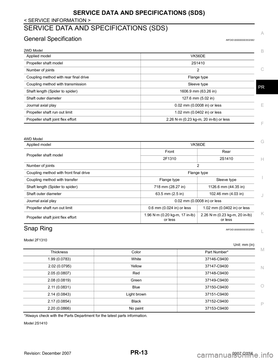
General SpecificationINFOID:0000000003532582
2WD Model
4WD Model
Snap RingINFOID:0000000003532583
Model 2F1310
Unit: mm (in)
*Always check with the Parts Department for the latest parts information.
Model 2S1410
Applied modelVK56DE
Propeller shaft model2S1410
Number of joints2
Coupling method with rear final drive Flange type
Coupling method with transmission Sleeve type
Shaft length (Spider to spider) 1606.9 mm (63.26 in)
Shaft outer diameter 127.6 mm (5.02 in)
Journal axial play 0.02 mm (0.0008 in) or less
Propeller shaft run out limit 1.02 mm (0.0402 in) or less
Propeller shaft joint flex effort 2.26 N·m (0.23 kg-m, 20 in-lb) or less
Applied modelVK56DE
Propeller shaft modelFront Rear
2F1310 2S1410
Number of joints2
Coupling method with front final drive Flange type
Coupling method with transfer Flange type Sleeve type
Shaft length (Spider to spider) 718 mm (28.27 in) 1126.6 mm (44.35 in)
Shaft outer diameter 63.5 mm (2.5 in) 102.46 mm (4.03 in)
Journal axial play 0.02 mm (0.0008 in) or less
Propeller shaft run out limit 0.6 mm (0.024 in) or less 1.02 mm (0.0402 in) or less
Propeller shaft joint flex effort1.96 N·m (0.20 kg-m, 17 in-lb)
or less2.26 N·m (0.23 kg-m, 20 in-lb)
or less
Thickness Color Part Number*
1.99 (0.0783) White 37146-C9400
2.02 (0.0795) Yellow 37147-C9400
2.05 (0.0807) Red 37148-C9400
2.08 (0.0819) Green 37149-C9400
2.11 (0.0831) Blue 37150-C9400
2.14 (0.0843) Light brown 37151-C9400
2.17 (0.0854) Black 37152-C9400
2.20 (0.0866) No paint 37153-C9400
Page 2502 of 3061

STEERING COLUMN
PS-11
< SERVICE INFORMATION >
C
D
E
F
H
I
J
K
L
MA
B
PS
N
O
P
4. Remove lock nut and bolt, then separate upper shaft from upper
joint.
5. Remove two nuts and two bolts, then remove steering column
assembly from steering member.
6. Remove hole cover seal and clamp.
7. Remove mounting nuts, then remove hole cover from dash panel.
8. Raise vehicle, then remove mounting bolt (lower side) of lower
joint shaft and remove lower joint shaft and upper shaft as an
assembly.
INSPECTION AFTER REMOVAL
• Check for damage to steering column jacket tube. If damage is found, replace steering column with new
one.
• If vehicle has been in a collision, check column length “L1” and
“L2” as shown. If out of specification, replace steering column with
new one.
• Check for proper lubrication, apply grease as necessary.
INSTALLATION
Installation is in the reverse order of removal.
CAUTION:
LGIA0027E
LGIA0028E
LGIA0029E
Steering column length
L1 : 158 mm (6.22 in)
L2 : 262 mm (10.31 in)
SGIA0475E
Page 2505 of 3061

PS-14
< SERVICE INFORMATION >
STEERING COLUMN
3. If the vehicle has been involved in a collision, or if noise and rat-
tles are heard during a turn, check the length "L" of the column.
If out of specification, replace the steering column as an assem-
bly.
4. Check for proper lubrication, apply grease as necessary.
5. Check for wear around the seal edges, replace the steering col-
umn as an assembly as necessary.
6. Check for corrosion or pitting around the seal sliding area.Steering column length "L" : 610 mm (24.02 in)
WGIA0080E
Page 2511 of 3061

PS-20
< SERVICE INFORMATION >
POWER STEERING GEAR AND LINKAGE
5. Crimp the large-diameter boot clamps, using Tool.
6. Install the cylinder tubes to the gear housing assembly.
7. Install the lock nuts and outer sockets to the inner sockets.
8. Thread the outer sockets onto the inner sockets to the specified
length "L", then tighten the lock nuts to the specification. Refer to
PS-15, "
Removal and Installation". Reconfirm that the tie-rod
length "L" is within specification.Tool number : KV40107300 ( — )
RAC1133D
Maximum inner socket
length "L": 115.2 mm (4.54 in)
SGIA0167E
Page 2516 of 3061

SERVICE DATA AND SPECIFICATIONS (SDS)
PS-25
< SERVICE INFORMATION >
C
D
E
F
H
I
J
K
L
MA
B
PS
N
O
P
SERVICE DATA AND SPECIFICATIONS (SDS)
Steering WheelINFOID:0000000003532835
Steering ColumnINFOID:0000000003532836
Inspection After Assembly
Unit: mm (in)
Inspection After Removal
Unit: mm (in)
Inspection After Installation
End play of the axial direction for steering wheel 0 mm (0 in)
Steering wheel play on the outer circumference 0 − 35 mm (0 − 1.38 in)
Steering wheel turning force 39 N (4 kg-f, 9 lb-f) or less
Steering column length “L”610 (24.02)
WGIA0080E
Steering column length “L2”262 (10.31)
Steering column length “L1” 158 (6.22)
Range “A”61.3 mm (2.41 in)
SGIA0475E
WGIA0083E
Page 2517 of 3061

PS-26
< SERVICE INFORMATION >
SERVICE DATA AND SPECIFICATIONS (SDS)
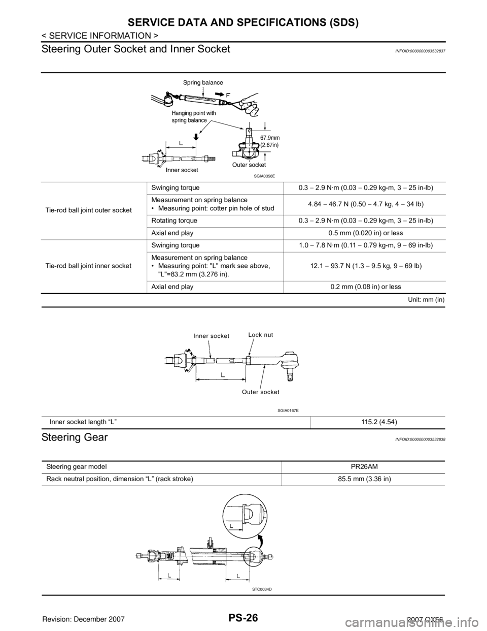
Steering Outer Socket and Inner Socket
INFOID:0000000003532837
Unit: mm (in)
Steering GearINFOID:0000000003532838
Tie-rod ball joint outer socketSwinging torque 0.3 − 2.9 N·m (0.03 − 0.29 kg-m, 3 − 25 in-lb)
Measurement on spring balance
• Measuring point: cotter pin hole of stud4.84 − 46.7 N (0.50 − 4.7 kg, 4 − 34 lb)
Rotating torque 0.3 − 2.9 N·m (0.03 − 0.29 kg-m, 3 − 25 in-lb)
Axial end play 0.5 mm (0.020 in) or less
Tie-rod ball joint inner socketSwinging torque 1.0 − 7.8 N·m (0.11 − 0.79 kg-m, 9 − 69 in-lb)
Measurement on spring balance
• Measuring point: "L" mark see above,
"L"=83.2 mm (3.276 in).12.1 − 93.7 N (1.3 − 9.5 kg, 9 − 69 lb)
Axial end play 0.2 mm (0.08 in) or less
SGIA0358E
Inner socket length “L” 115.2 (4.54)
SGIA0167E
Steering gear modelPR26AM
Rack neutral position, dimension “L” (rack stroke) 85.5 mm (3.36 in)
STC0034D