fuel INFINITI QX56 2007 Factory Service Manual
[x] Cancel search | Manufacturer: INFINITI, Model Year: 2007, Model line: QX56, Model: INFINITI QX56 2007Pages: 3061, PDF Size: 64.56 MB
Page 2613 of 3061

REAR SUSPENSION ASSEMBLY
RSU-23
< SERVICE INFORMATION >
C
D
F
G
H
I
J
K
L
MA
B
RSU
N
O
P
Wheel AlignmentInspectionINFOID:0000000003532671
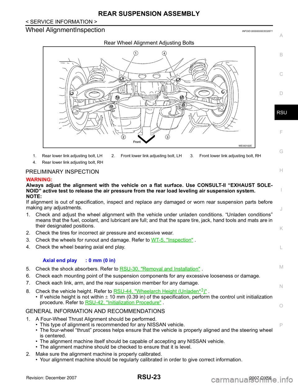
Rear Wheel Alignment Adjusting Bolts
PRELIMINARY INSPECTION
WARNING:
Always adjust the alignment with the vehicle on a flat surface. Use CONSULT-II “EXHAUST SOLE-
NOID” active test to release the air pressure from the rear load leveling air suspension system.
NOTE:
If alignment is out of specification, inspect and replace any damaged or worn rear suspension parts before
making any adjustments.
1. Check and adjust the wheel alignment with the vehicle under unladen conditions. “Unladen conditions”
means that the fuel, coolant, and lubricant are full; and that the spare tire, jack, hand tools and mats are in
their designated positions.
2. Check the tires for incorrect air pressure and excessive wear.
3. Check the wheels for runout and damage. Refer to WT-5, "
Inspection" .
4. Check the wheel bearing axial end play.
5. Check the shock absorbers. Refer to RSU-30, "
Removal and Installation" .
6. Check each mounting point of the suspension components for any excessive looseness or damage.
7. Check each link, arm, and the rear suspension member for any damage.
8. Check the vehicle height. Refer to RSU-44, "
Wheelarch Height (Unladen*1)" .
• If vehicle height is not within ± 10 mm (0.39 in) of the specification, perform the control unit initialization
procedure. Refer to RSU-42, "
Initialization Procedure" .
GENERAL INFORMATION AND RECOMMENDATIONS
1. A Four-Wheel Thrust Alignment should be performed.
• This type of alignment is recommended for any NISSAN vehicle.
• The four-wheel “thrust” process helps ensure that the vehicle is properly aligned and the steering wheel
is centered.
• The alignment machine itself should be capable of accepting any NISSAN vehicle.
• The alignment machine should be checked to ensure that it is level.
2. Make sure the alignment machine is properly calibrated.
• Your alignment machine should be regularly calibrated in order to give correct information.
WEIA0102E
1. Rear lower link adjusting bolt, LH 2. Front lower link adjusting bolt, LH 3. Front lower link adjusting bolt, RH
4. Rear lower link adjusting bolt, RH
Axial end play : 0 mm (0 in)
Page 2619 of 3061

REAR SUSPENSION MEMBER
RSU-29
< SERVICE INFORMATION >
C
D
F
G
H
I
J
K
L
MA
B
RSU
N
O
P
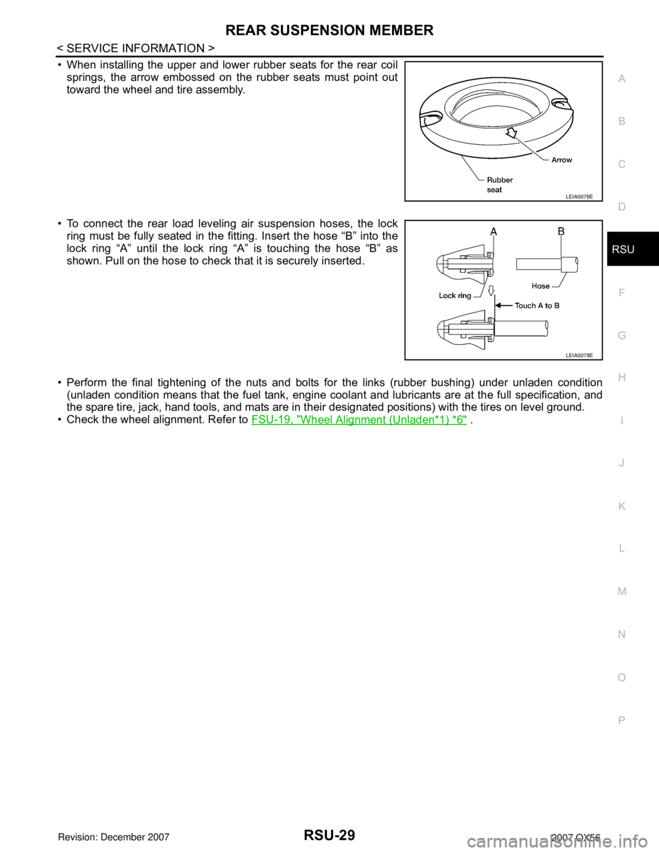
• When installing the upper and lower rubber seats for the rear coil
springs, the arrow embossed on the rubber seats must point out
toward the wheel and tire assembly.
• To connect the rear load leveling air suspension hoses, the lock
ring must be fully seated in the fitting. Insert the hose “B” into the
lock ring “A” until the lock ring “A” is touching the hose “B” as
shown. Pull on the hose to check that it is securely inserted.
• Perform the final tightening of the nuts and bolts for the links (rubber bushing) under unladen condition
(unladen condition means that the fuel tank, engine coolant and lubricants are at the full specification, and
the spare tire, jack, hand tools, and mats are in their designated positions) with the tires on level ground.
• Check the wheel alignment. Refer to FSU-19, "
Wheel Alignment (Unladen*1) *6" .
LEIA0076E
LEIA0078E
Page 2622 of 3061

RSU-32
< SERVICE INFORMATION >
SUSPENSION ARM
• Check the ball joint. Replace the suspension arm assembly if any
of the following conditions exist:
- Ball stud is worn.
- Joint is hard to swing.
- Play in axial direction is excessive.
INSTALLATION
Installation is in the reverse order of removal.
• Tighten the nuts and bolts to specification. Refer to RSU-21, "
Component" .
• Perform the final tightening of the nuts and bolts for the links (rubber bushing) under unladen condition
(unladen condition means that the fuel tank, engine coolant and lubricants are at the full specification, and
the spare tire, jack, hand tools, and mats are in their designated positions) with the tires on level ground.
• Check the wheel alignment. Refer to RSU-23, "
Wheel AlignmentInspection" . Swinging force “A” : Refer to RSU-43, "
Ball Joint" .
Turning force “B” : Refer to RSU-43, "
Ball Joint" .
Vertical end play “C” : Refer to RSU-43, "
Ball Joint" .
SFA858A
Page 2624 of 3061

RSU-34
< SERVICE INFORMATION >
FRONT LOWER LINK
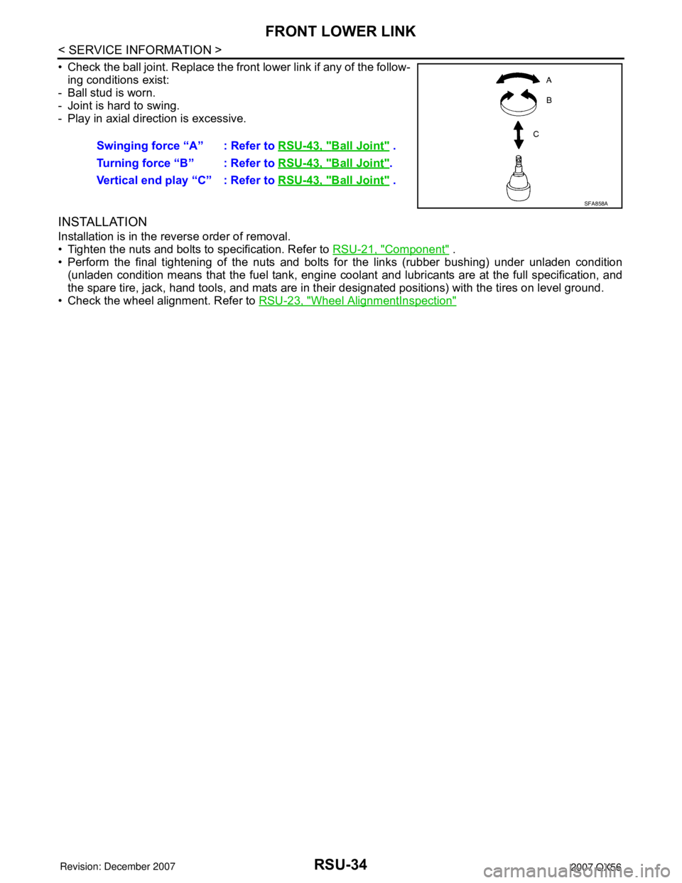
• Check the ball joint. Replace the front lower link if any of the follow-
ing conditions exist:
- Ball stud is worn.
- Joint is hard to swing.
- Play in axial direction is excessive.
INSTALLATION
Installation is in the reverse order of removal.
• Tighten the nuts and bolts to specification. Refer to RSU-21, "
Component" .
• Perform the final tightening of the nuts and bolts for the links (rubber bushing) under unladen condition
(unladen condition means that the fuel tank, engine coolant and lubricants are at the full specification, and
the spare tire, jack, hand tools, and mats are in their designated positions) with the tires on level ground.
• Check the wheel alignment. Refer to RSU-23, "
Wheel AlignmentInspection"
Swinging force “A” : Refer to RSU-43, "Ball Joint" .
Turning force “B” : Refer to RSU-43, "
Ball Joint".
Vertical end play “C” : Refer to RSU-43, "
Ball Joint" .
SFA858A
Page 2634 of 3061

RSU-44
< SERVICE INFORMATION >
SERVICE DATA AND SPECIFICATIONS (SDS)
Wheelarch Height (Unladen*
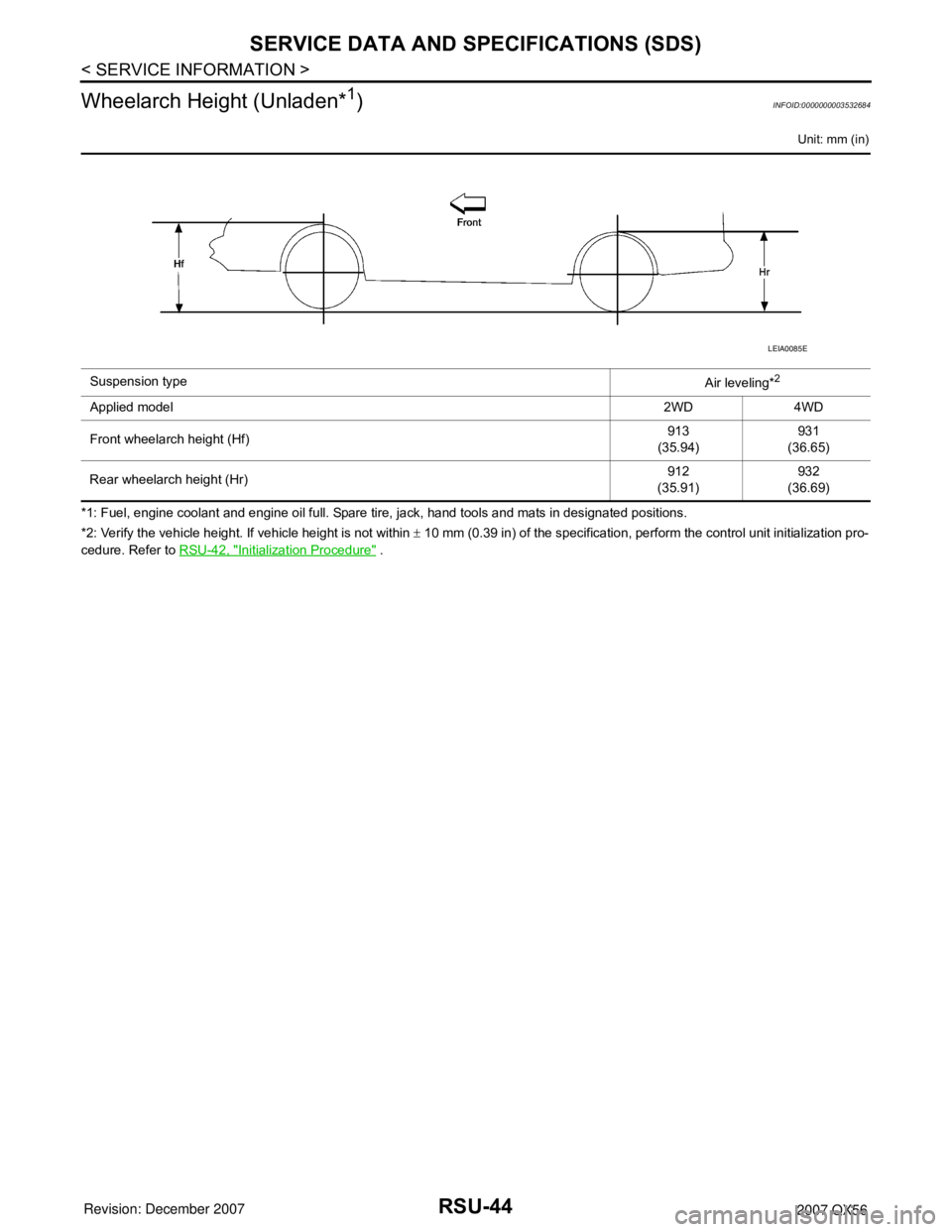
1)INFOID:0000000003532684
Unit: mm (in)
*1: Fuel, engine coolant and engine oil full. Spare tire, jack, hand tools and mats in designated positions.
*2: Verify the vehicle height. If vehicle height is not within ± 10 mm (0.39 in) of the specification, perform the control unit initialization pro-
cedure. Refer to RSU-42, "
Initialization Procedure" . Suspension type
Air leveling*
2
Applied model2WD 4WD
Front wheelarch height (Hf)913
(35.94)931
(36.65)
Rear wheelarch height (Hr)912
(35.91)932
(36.69)
LEIA0085E
Page 2660 of 3061

SC-12
< SERVICE INFORMATION >
STARTING SYSTEM
DIAGNOSTIC PROCEDURE 1
Check Starter Motor Circuit
1.CHECK POWER SUPPLY TO STARTER MOTOR
1. Remove the fuel pump fuse.
2. Crank or start the engine (where possible) until the fuel pressure is released.
3. Turn the ignition switch OFF.
*1SC-6, "Trouble Diagnosis with Bat-
tery/Starting/Charging System
Te s t e r"
*2 "MINIMUM SPECIFICATION OF
CRANKING VOLTAGE REFERENC-
ING COOLANT TEMPERATURE"*3 "DIAGNOSTIC PROCEDURE 1"
*4 "DIAGNOSTIC PROCEDURE 2"
WKIA4532E
Page 2661 of 3061

STARTING SYSTEM
SC-13
< SERVICE INFORMATION >
C
D
E
F
G
H
I
J
L
MA
B
SC
N
O
P
4. Check that the starter motor connector F27 connection is clean and tight.
5. Check voltage between starter motor connector F27 terminal 2
and ground using a digital circuit tester.
OK or NG
OK >> GO TO 2.
NG >> Check harness between the battery and the starter
motor for open circuit.
2.CHECK VOLTAGE DROP ON STARTER MOTOR CIRCUIT
Check voltage between starter motor connector F27 terminal 2 and
battery positive terminal using a digital circuit tester.
OK or NG
OK >> GO TO 3.
NG >> Check harness between the battery and the starter
motor for poor continuity.
3.CHECK VOLTAGE DROP ON STARTER MOTOR GROUND CIRCUIT
Check voltage between starter motor case and battery negative ter-
minal using a digital circuit tester.
OK or NG
OK >> Starter motor ground circuit is OK. Further inspection is
necessary. Refer to "WORK FLOW" .
NG >> Check harness between the starter motor case and
ground for poor continuity.
DIAGNOSTIC PROCEDURE 2
Check Magnetic Switch Circuit
1.CHECK POWER SUPPLY FOR MAGNETIC SWITCH
1. Remove the fuel pump fuse.
2. Crank or start the engine (where possible) until the fuel pressure is released.
3. Turn the ignition switch OFF.
4. Disconnect starter motor connector F28.
5. Check voltage between starter motor connector F28 terminal 1
and ground using a digital circuit tester.
OK or NG
OK >> GO TO 2.
NG >> Check the following.
• 40A fusible link (letter m , located in fuse and fusible
link box)
• Ignition switch Battery voltage should ex-
ist.
WKIA2105E
Ignition switch in
START.: Less than 0.5V
WKIA2106E
Ignition switch in
START.: Less than 0.2V
WKIA3437E
Ignition switch in
START.: Battery voltage
WKIA2108E
Page 2663 of 3061

CHARGING SYSTEM
SC-15
< SERVICE INFORMATION >
C
D
E
F
G
H
I
J
L
MA
B
SC
N
O
P
CHARGING SYSTEM
System DescriptionINFOID:0000000003533323
The generator provides DC voltage to operate the vehicle's electrical system and to keep the battery charged.
The voltage output is controlled by the IC regulator.
Power is supplied at all times to generator terminal 3 through
• 10A fuse (No. 30, located in the fuse and fusible link box).
Terminal 1 supplies power to charge the battery and operate the vehicle's electrical system. Output voltage is
controlled by the IC regulator at terminal 3 detecting the input voltage. A pulse width modulated (PWM) signal
is sent from terminal 37 of the IPDM E/R to terminal 4 of the generator. The ECM determines the duty cycle of
the power generation variable voltage control system. The charging circuit is protected by the 140A fusible link
[letter a, located in the fusible link box (battery)].
The generator is grounded through the engine.
With the ignition switch in the ON or START position, power is supplied
• through 10A fuse [No. 14, located in the fuse block (J/B)]
• to combination meter terminal 24 for the charge warning lamp.
Ground is supplied to terminal 13 of the combination meter through terminal 2 of the generator. With power
and ground supplied, the charge warning lamp will illuminate. When the generator is providing sufficient volt-
age with the engine running, the ground is opened and the charge warning lamp will go off. If the charge warn-
ing lamp illuminates with the engine running, a fault is indicated. The IC regulator warning function activates to
illuminate “CHARGE” warning lamp, if any of the following symptoms occur while generator is operating:
• Excessive voltage is produced.
• No voltage is produced.
POWER GENERATION VARIABLE VOLTAGE CONTROL SYSTEM
NOTE:
Power generation variable voltage control system has been adopted. By varying the voltage to the generator,
engine load due to power generation of the generator is reduced and fuel consumption is decreased.
Operation
• The battery current sensor detects the charging/discharging current of the battery. ECM judges the battery
condition based on this signal.
• ECM judges whether to control voltage according to the battery condition.
• ECM calculates the target power generation voltage according to the battery condition and sends the calcu-
lated value, through CAN lines, as the power generation command value to IPDM E/R.
• IPDM E/R converts the received power generation command value into the power generation command sig-
nal (PWM signal) and sends it to the IC regulator.
• The IC regulator performs final control over the power generation voltage.
• When there is no power generation command signal, the generator performs the normal power generation
according to the characteristic of the IC regulator.
NOTE:
When any malfunction is detected in the power generation variable voltage control system, power generation
is performed according to the characteristic of the IC regulator in the generator.
PKIB4908E