INFINITI QX56 2007 Factory Service Manual
Manufacturer: INFINITI, Model Year: 2007, Model line: QX56, Model: INFINITI QX56 2007Pages: 3061, PDF Size: 64.56 MB
Page 381 of 3061
PRECAUTIONSATC-11
< SERVICE INFORMATION >
C
DE
F
G H
I
K L
M A
B
AT C
N
O P
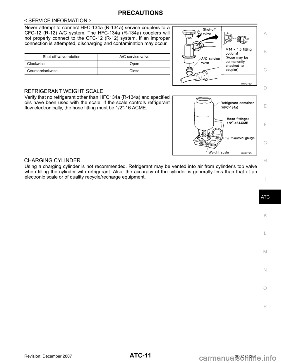
Never attempt to connect HFC-134a (R-134a) service couplers to a
CFC-12 (R-12) A/C system. T he HFC-134a (R-134a) couplers will
not properly connect to the CFC-12 (R-12) system. If an improper
connection is attempted, dischar ging and contamination may occur.
REFRIGERANT WEIGHT SCALE
Verify that no refrigerant other than HFC134a (R-134a) and specified
oils have been used with the scale. If the scale controls refrigerant
flow electronically, the hose fitting must be 1/2”-16 ACME.
CHARGING CYLINDER
Using a charging cylinder is not recommended. Refrigerant may be vented into air from cylinder's top valve
when filling the cylinder with refrigerant. Also, the accura cy of the cylinder is generally less than that of an
electronic scale or of quality recycle/recharge equipment.
Shut-off valve rotati on A/C service valve
Clockwise Open
Counterclockwise Close
RHA273D
RHA274D
Page 382 of 3061
ATC-12
< SERVICE INFORMATION >
PREPARATION
PREPARATION
Special Service ToolINFOID:0000000003533226
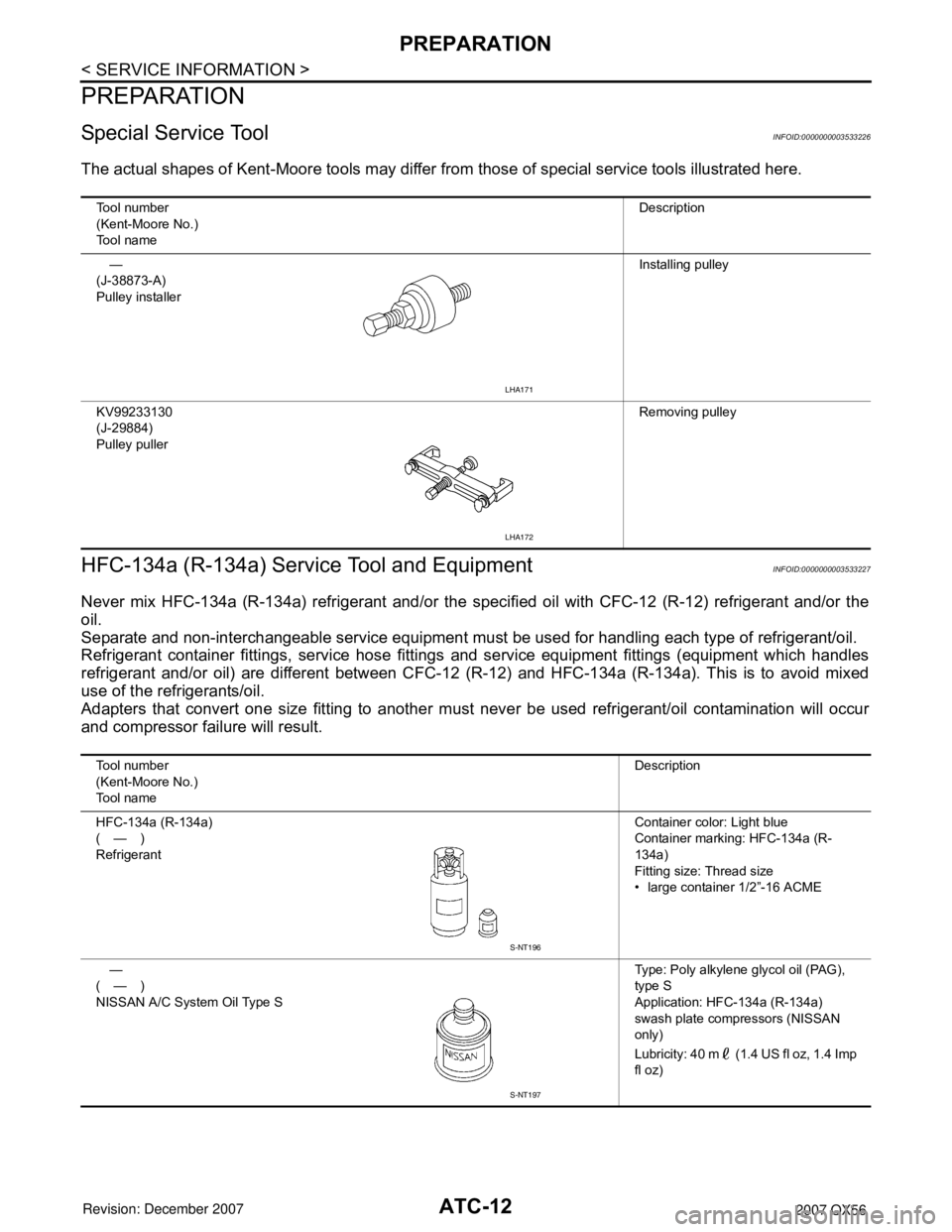
The actual shapes of Kent-Moore tools may differ from those of special service tools illustrated here.
HFC-134a (R-134a) Service Tool and EquipmentINFOID:0000000003533227
Never mix HFC-134a (R-134a) refrigerant and/or the spec ified oil with CFC-12 (R-12) refrigerant and/or the
oil.
Separate and non-interchangeable service equipment must be used for handling each type of refrigerant/oil.
Refrigerant container fittings, service hose fittings and service equipment fittings (equipment which handles
refrigerant and/or oil) are different between CFC-12 (R-12) and HFC-134a (R-134a). This is to avoid mixed
use of the refrigerants/oil.
Adapters that convert one size fitting to another must never be used refrigerant/oil contamination will occur
and compressor failure will result.
Tool number
(Kent-Moore No.)
Tool name Description
—
(J-38873-A)
Pulley installer Installing pulley
KV99233130
(J-29884)
Pulley puller Removing pulley
LHA171
LHA172
Tool number
(Kent-Moore No.)
Tool nameDescription
HFC-134a (R-134a)
(—)
Refrigerant Container color: Light blue
Container marking: HFC-134a (R-
134a)
Fitting size: Thread size
• large container 1/2”-16 ACME
—
(—)
NISSAN A/C System Oil Type S Type: Poly alkylene glycol oil (PAG),
type S
Application: HFC-134a (R-134a)
swash plate compressors (NISSAN
only)
Lubricity: 40 m (1.4 US fl oz, 1.4 Imp
fl oz)
S-NT196
S-NT197
Page 383 of 3061
PREPARATIONATC-13
< SERVICE INFORMATION >
C
DE
F
G H
I
K L
M A
B
AT C
N
O P
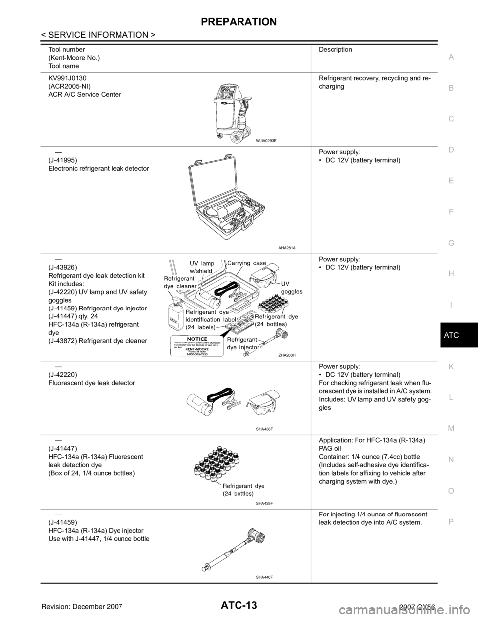
KV991J0130
(ACR2005-NI)
ACR A/C Service Center Refrigerant recovery
, recycling and re-
charging
—
(J-41995)
Electronic refrigerant leak detector Power supply:
• DC 12V (battery terminal)
—
(J-43926)
Refrigerant dye leak detection kit
Kit includes:
(J-42220) UV lamp and UV safety
goggles
(J-41459) Refrigerant dye injector
(J-41447) qty. 24
HFC-134a (R-134a) refrigerant
dye
(J-43872) Refrigerant dye cleaner Power supply:
• DC 12V (battery terminal)
—
(J-42220)
Fluorescent dye leak detector Power supply:
• DC 12V (battery terminal)
For checking refrigerant leak when flu-
orescent dye is installed in A/C system.
Includes: UV lamp and UV safety gog-
gles
—
(J-41447)
HFC-134a (R-134a) Fluorescent
leak detection dye
(Box of 24, 1/4 ounce bottles) Application: For HFC-134a (R-134a)
PA G o i l
Container: 1/4 ounce (7.4cc) bottle
(Includes self-adhesive dye identifica-
tion labels for affixing to vehicle after
charging system with dye.)
—
(J-41459)
HFC-134a (R-134a) Dye injector
Use with J-41447, 1/4 ounce bottle For injecting 1/4 ounce of fluorescent
leak detection dye into A/C system.
Tool number
(Kent-Moore No.)
Tool name
Description
WJIA0293E
AHA281A
ZHA200H
SHA438F
SHA439F
SHA440F
Page 384 of 3061
ATC-14
< SERVICE INFORMATION >
PREPARATION
Commercial Service Tool
INFOID:0000000003533228
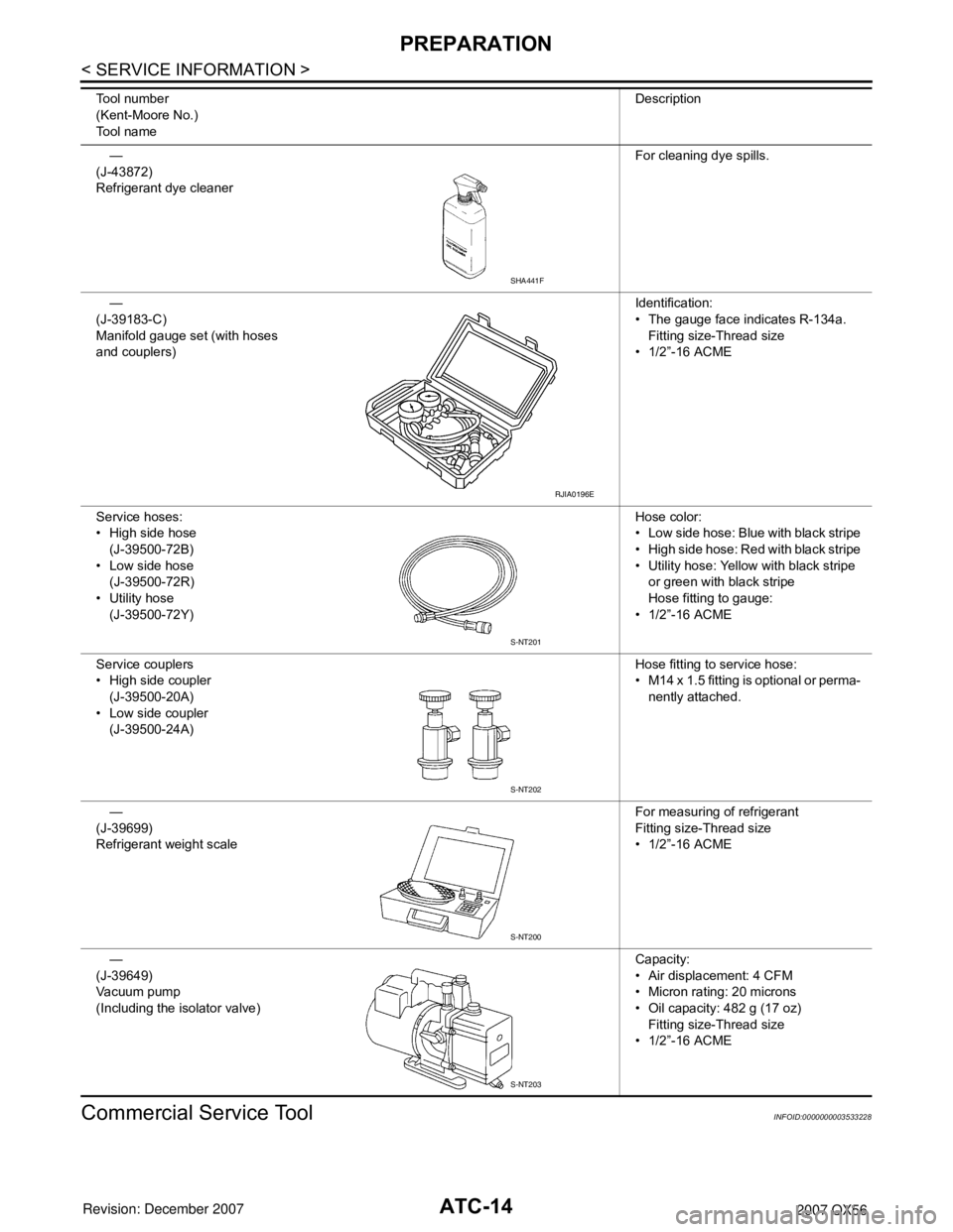
—
(J-43872)
Refrigerant dye cleaner For cleaning dye spills.
—
(J-39183-C)
Manifold gauge set (with hoses
and couplers) Identification:
• The gauge face indicates R-134a.
Fitting size-Thread size
• 1/2”-16 ACME
Service hoses:
• High side hose (J-39500-72B)
• Low side hose
(J-39500-72R)
• Utility hose (J-39500-72Y) Hose color:
• Low side hose: Blue with black stripe
• High side hose: Red with black stripe
• Utility hose: Yellow with black stripe
or green with black stripe
Hose fitting to gauge:
• 1/2”-16 ACME
Service couplers
• High side coupler (J-39500-20A)
• Low side coupler (J-39500-24A) Hose fitting to service hose:
• M14 x 1.5 fitting is optional or perma-
nently attached.
—
(J-39699)
Refrigerant weight scale For measuring of refrigerant
Fitting size-Thread size
• 1/2”-16 ACME
—
(J-39649)
Vacuum pump
(Including the isolator valve) Capacity:
• Air displacement: 4 CFM
• Micron rating: 20 microns
• Oil capacity: 482 g (17 oz)
Fitting size-Thread size
• 1/2”-16 ACME
Tool number
(Kent-Moore No.)
Tool name
Description
SHA441F
RJIA0196E
S-NT201
S-NT202
S-NT200
S-NT203
Page 385 of 3061
PREPARATIONATC-15
< SERVICE INFORMATION >
C
DE
F
G H
I
K L
M A
B
AT C
N
O P
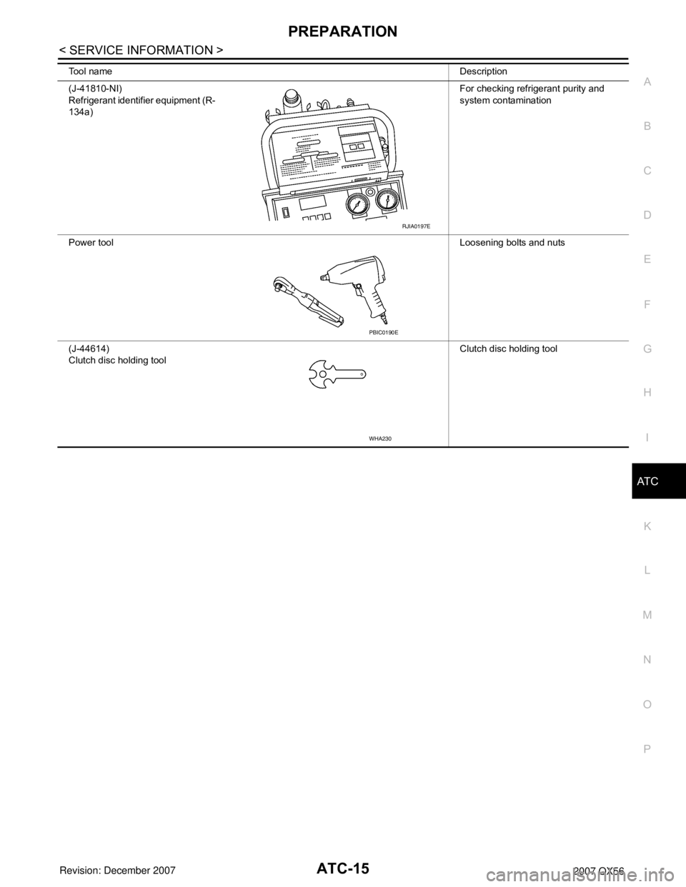
Tool name Description
(J-41810-NI)
Refrigerant identifier equipment (R-
134a) For checking refrigerant purity and
system contamination
Power tool Loosening bolts and nuts
(J-44614)
Clutch disc holding tool Clutch disc holding tool
RJIA0197E
PBIC0190E
WHA230
Page 386 of 3061

ATC-16
< SERVICE INFORMATION >
REFRIGERATION SYSTEM
REFRIGERATION SYSTEM
Refrigerant CycleINFOID:0000000003533229
REFRIGERANT FLOW
The refrigerant flows in the standard pattern, that is, through the compressor, the condenser with liquid tank,
through the front and rear evaporators, and back to the compressor. The refrigerant evaporation through the
evaporator coils are controlled by front and rear exter nally equalized expansion valves, located inside the front
and rear evaporator cases.
Refrigerant System ProtectionINFOID:0000000003533230
REFRIGERANT PRESSURE SENSOR
The refrigerant system is protected against excessively high or low pressures by the refrigerant pressure sen-
sor, located on the condenser. If the system pressure rise s above or falls below the specifications, the refriger-
ant pressure sensor detects the pressure inside t he refrigerant line and sends a voltage signal to the ECM.
The ECM de-energizes the A/C relay to disengage the magnetic compressor clutch when pressure on the high
pressure side detected by refrigerant pressu re sensor is over about 2,746 kPa (28 kg/cm
2, 398 psi), or below
about 120 kPa (1.22 kg/cm
2, 17.4 psi).
PRESSURE RELIEF VALVE
The refrigerant system is also protected by a pressure relief valve, located in the rear head of the compressor.
When the pressure of refrigerant in the system incr eases to an abnormal level [more than 2,990 kPa (30.5 kg/
Page 387 of 3061
![INFINITI QX56 2007 Factory Service Manual
REFRIGERATION SYSTEMATC-17
< SERVICE INFORMATION >
C
DE
F
G H
I
K L
M A
B
AT C
N
O P
cm2, 433.6 psi)], the release port on the pressure relief valve automatically opens and releases refrigerant into INFINITI QX56 2007 Factory Service Manual
REFRIGERATION SYSTEMATC-17
< SERVICE INFORMATION >
C
DE
F
G H
I
K L
M A
B
AT C
N
O P
cm2, 433.6 psi)], the release port on the pressure relief valve automatically opens and releases refrigerant into](/img/42/57029/w960_57029-386.png)
REFRIGERATION SYSTEMATC-17
< SERVICE INFORMATION >
C
DE
F
G H
I
K L
M A
B
AT C
N
O P
cm2, 433.6 psi)], the release port on the pressure relief valve automatically opens and releases refrigerant into
the atmosphere.
Component Part LocationINFOID:0000000003533231
FRONT REFRIGERATION SYSTEM
WJIA1342E
Page 388 of 3061

ATC-18
< SERVICE INFORMATION >
REFRIGERATION SYSTEM
REAR REFRIGERATION SYSTEM
1. Defroster nozzle 2. LH side demister duct 3. LH ventilator duct
4. RH side demister duct 5. RH ventilator duct 6. Center ventilator duct
7. Front heater and cooling unit assembly 8. Floor duct 9. Clips
10. Heat duct
WJIA0956E
Page 389 of 3061

REFRIGERATION SYSTEMATC-19
< SERVICE INFORMATION >
C
DE
F
G H
I
K L
M A
B
AT C
N
O P1. Rear floor duct 2. Rear heater and cooling unit assembly 3. Rear lower overhead duct
4. Rear upper overhead duct
LJIA0142E
Page 390 of 3061

ATC-20
< SERVICE INFORMATION >
OIL
OIL
Maintenance of Oil Quantity in CompressorINFOID:0000000003533232
The oil in the compressor circulates through the system with the refrigerant. Add oil to compressor when
replacing any component or after a large refrigerant leakage has occurred. It is important to maintain the spec-
ified amount.
If oil quantity is not maintained properly, the following malfunctions may result:
• Lack of oil: May lead to a seized compressor
• Excessive oil: Inadequate cooling (thermal exchange interference)
OIL
Name: NISSAN A/C System Oil Type S or equivalent
CHECKING AND ADJUSTING
CAUTION:
If excessive oil leakage is noted, do no t perform the oil return operation.
Start the engine and set the following conditions:
Test Condition
• Engine speed: Idling to 1,200 rpm
• A/C switch: On
• Blower fan speed: MAX position
• Temp. control: Optional [Set so that intake air temperature is 25 ° to 30 ° C (77 ° to 86 °F)]
• Intake position: Recirculation ( )
• Perform oil return operation for about ten minutes
Adjust the oil quantity according to the following table.
Oil Adjusting Procedure for Components Replacement Except Compressor
After replacing any of the following major component s, add the correct amount of oil to the system.
Amount of oil to be added :
• *1: If refrigerant leak is small, no addition of oil is needed.
Oil Adjustment Procedure for Compressor Replacement
Part replaced Oil to be added to system
Remarks
Amount of oil
m (US fl oz, Imp fl oz)
Front evaporator 75 (2.5, 2.6) —
Rear evaporator 75 (2.5, 2.6) —
Condenser 75 (2.5, 2.6) —
Liquid tank 5 (0.2, 0.2) Add if compressor is not replaced.
In case of refrigerant leak 30 (1.0, 1.1) Large leak
— Small leak *1