oil change INFINITI QX56 2007 Factory Owner's Guide
[x] Cancel search | Manufacturer: INFINITI, Model Year: 2007, Model line: QX56, Model: INFINITI QX56 2007Pages: 3061, PDF Size: 64.56 MB
Page 2509 of 3061

PS-18
< SERVICE INFORMATION >
POWER STEERING GEAR AND LINKAGE
• Before performing disassembly, clean steering gear assembly with kerosene. Be careful not to bring
any kerosene into contact with the discharge and return port connectors.
DISASSEMBLY
1. Remove cylinder tubes from gear housing assembly.
2. Loosen lock nuts of outer sockets, and remove outer sockets.
3. Remove boot clamps of the small diameter side and the large diameter side, then remove boot.
CAUTION:
When removing boots, be careful not to damage inner socket and gear housing assembly. If they
are damaged, change them to avoid oil leaks.
4. Remove inner sockets.
INSPECTION AFTER DISASSEMBLY
Boot
Check boot for tears, cracks and deformation. Replace if necessary.
Gear Housing Assembly
Check gear housing assembly for dents, cracks or damage. Replace as an assembly if necessary.
Outer Socket and Inner Socket
SWING TORQUE
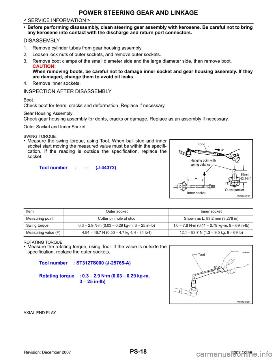
• Measure the swing torque, using Tool. When ball stud and inner
socket start moving the measured value must be within the specifi-
cation. If the reading is outside the specification, replace the
socket.
ROTATING TORQUE• Measure the rotating torque, using Tool. If the value is outside the
specification, replace the outer sockets.
AXIAL END PLAY
Tool number : — (J-44372)
WGIA0131E
Item Outer socket Inner socket
Measuring point Cotter pin hole of stud Shown as L: 83.2 mm (3.276 in)
Swing torque 0.3 − 2.9 N·m (0.03 − 0.29 kg-m, 3 − 25 in-lb) 1.0 − 7.8 N·m (0.11 − 0.79 kg-m, 9 − 69 in-lb)
Measuring value (F) 4.84 − 46.7 N (0.50 − 4.7 kg-f, 4 - 34 lb-f) 12.1 − 93.7 N (1.3 − 9.5 kg, 9 − 69 lb)
Tool number : ST3127S000 (J-25765-A)
Rotating torque : 0.3 − 2.9 N·m (0.03 − 0.29 kg-m,
3 − 25 in-lb)
WGIA0132E
Page 2576 of 3061

REAR FINAL DRIVE ASSEMBLY
RFD-19
< SERVICE INFORMATION >
C
E
F
G
H
I
J
K
L
MA
B
RFD
N
O
P Backlash
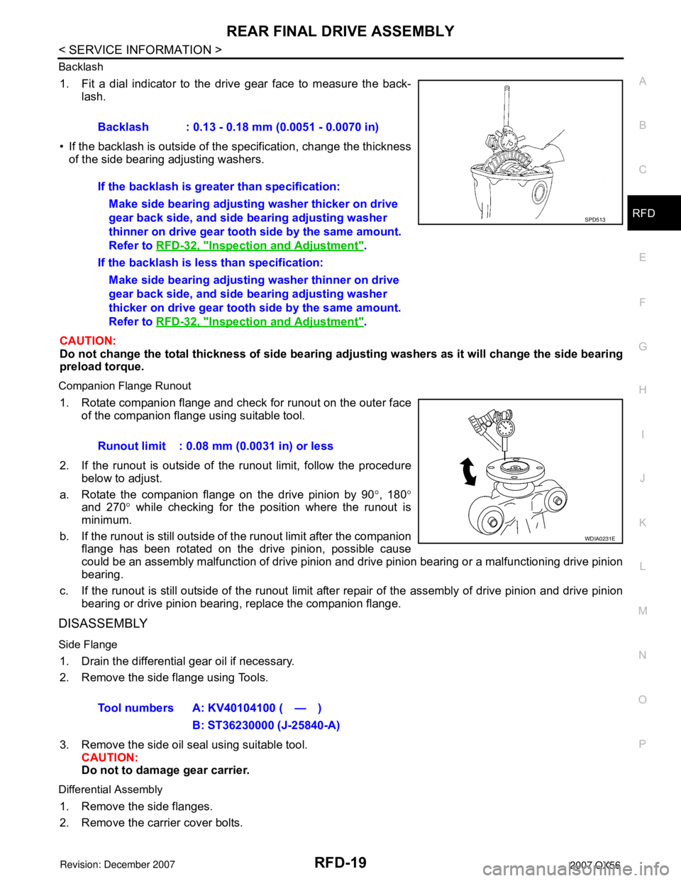
1. Fit a dial indicator to the drive gear face to measure the back-
lash.
• If the backlash is outside of the specification, change the thickness
of the side bearing adjusting washers.
CAUTION:
Do not change the total thickness of side bearing adjusting washers as it will change the side bearing
preload torque.
Companion Flange Runout
1. Rotate companion flange and check for runout on the outer face
of the companion flange using suitable tool.
2. If the runout is outside of the runout limit, follow the procedure
below to adjust.
a. Rotate the companion flange on the drive pinion by 90°, 180°
and 270° while checking for the position where the runout is
minimum.
b. If the runout is still outside of the runout limit after the companion
flange has been rotated on the drive pinion, possible cause
could be an assembly malfunction of drive pinion and drive pinion bearing or a malfunctioning drive pinion
bearing.
c. If the runout is still outside of the runout limit after repair of the assembly of drive pinion and drive pinion
bearing or drive pinion bearing, replace the companion flange.
DISASSEMBLY
Side Flange
1. Drain the differential gear oil if necessary.
2. Remove the side flange using Tools.
3. Remove the side oil seal using suitable tool.
CAUTION:
Do not to damage gear carrier.
Differential Assembly
1. Remove the side flanges.
2. Remove the carrier cover bolts.Backlash : 0.13 - 0.18 mm (0.0051 - 0.0070 in)
If the backlash is greater than specification:
Make side bearing adjusting washer thicker on drive
gear back side, and side bearing adjusting washer
thinner on drive gear tooth side by the same amount.
Refer to RFD-32, "
Inspection and Adjustment".
If the backlash is less than specification:
Make side bearing adjusting washer thinner on drive
gear back side, and side bearing adjusting washer
thicker on drive gear tooth side by the same amount.
Refer to RFD-32, "
Inspection and Adjustment".
SPD513
Runout limit : 0.08 mm (0.0031 in) or less
WDIA0231E
Tool numbers A: KV40104100 ( — )
B: ST36230000 (J-25840-A)
Page 2840 of 3061

TF-18
< SERVICE INFORMATION >
ALL-MODE 4WD SYSTEM
LINE PRESSURE SWITCH
• With the transfer system design, control of the oil pressure provides the transmission of drive torque to the
front wheels. The main pressure to control the oil pressure is referred to as the line pressure.
• The line pressure switch determines whether or not adequate line pressure has built up under different oper-
ating conditions.
• The line pressure switch turns ON when line pressure is produced.
• The line pressure switch senses line pressure abnormalities and turns the 4WD warning lamp ON.
CLUTCH PRESSURE SWITCH
• The clutch pressure switch determines whether or not adequate clutch pressure has built up under different
operating conditions.
• The clutch pressure switch turns ON when clutch pressure is produced.
• The clutch pressure switch senses clutch pressure abnormalities and turns the 4WD warning lamp ON.
TRANSFER FLUID TEMPERATURE SENSOR
The transfer temperature sensor detects the transfer fluid temperature and sends a signal to the transfer con-
trol unit.
TRANSFER CONTROL UNIT
• Transfer control unit controls transfer control device by input signals of each sensor and each switch.
• Self-diagnosis can be done.
TRANSFER CONTROL DEVICE
The transfer control device changes the state of transfer assembly between 2WD, AUTO, 4H⇔4LO with the
2WD, AUTO, 4H and 4LO signals of 4WD shift switch.
NOTE:
• To shift between 4H⇔4LO, stop the vehicle, depress the brake pedal and shift the transmission selector to
the "N" position. Depress and turn the 4WD shift switch. The shift switch will not shift to the desired mode if
the transmission is not in "N" or the vehicle is moving. The 4LO indicator lamp will be lit when the 4LO is
engaged.
• Actuator motor and actuator position switch are integrated.
4WD SHIFT SWITCH AND INDICATOR LAMP
4WD Shift Switch
The 4WD shift switch allows selection from 2WD, AUTO, 4H or 4LO.
4WD Shift Indicator Lamp
• Displays driving conditions selected by 4WD shift switch with 2WD, AUTO and 4H indicators while engine is
running. (When 4WD warning lamp is turned on, all 4WD shift indicator lamps are turned off.)
• Turns ON for approximately 1 second when ignition switch is turned ON, for purpose of lamp check.
4LO Indicator Lamp
• Displays 4LO condition while engine is running. 4LO indicator lamp flashes if transfer gear does not shift
completely under 2WD, AUTO, 4H⇔4LO. (When 4WD warning lamp is turned on, 4LO indicator lamp is
turned off.)
• Turns ON for approximately 1 second when ignition switch is turned ON, for purpose of lamp check.
4WD WARNING LAMP
Turns ON or FLASH when there is a malfunction in 4WD system.
Also turns ON when ignition switch is turned ON, for purpose of lamp check. Turns OFF for approximately 1
second after the engine starts if system is normal.
4WD Warning Lamp Indication
Condition Content 4WD warning lamp
During self-diagnosis Indicates the malfunction position by number of flickers. Flickers at malfunction mode.
Lamp check*Checks the lamp by turning ON during engine starting. After
engine starts, it turns OFF if there are no malfunctions.ON
Malfunction in 4WD system*Turns ON to indicate malfunction. When ignition switch is
turned to “OFF” or the malfunction is corrected, it turns OFF.ON
When vehicle is driven with different
diameters of front and rear tiresFlickers once every 2 seconds.
Turns OFF when ignition switch is “OFF”.Flickers once every 2 sec-
onds.