lock INFINITI QX56 2007 Factory Workshop Manual
[x] Cancel search | Manufacturer: INFINITI, Model Year: 2007, Model line: QX56, Model: INFINITI QX56 2007Pages: 3061, PDF Size: 64.56 MB
Page 273 of 3061

A/T SHIFT LOCK SYSTEM
AT-203
< SERVICE INFORMATION >
D
E
F
G
H
I
J
K
L
MA
B
AT
N
O
P
Wiring Diagram - AT - SHIFTINFOID:0000000003532471
BCWA0502E
Page 274 of 3061

AT-204
< SERVICE INFORMATION >
A/T SHIFT LOCK SYSTEM
Shift Lock Control Unit Reference Value
INFOID:0000000003532472
SHIFT LOCK HARNESS CONNECTOR TERMINALS LAYOUT
SHIFT LOCK CONTROL UNIT INSPECTION TABLE
Data are reference values.
NOTE:
Confirm that the pointer swings only momentarily because the output time is so short. If the inspection is done with an oscilloscope, it
should be observed that the power source voltage lasts for 3.5 to 10 ms.
Component InspectionINFOID:0000000003532473
SHIFT LOCK SOLENOID
WCIA0550E
TER-
MINAL
NO.WIRE
COLORITEM CONDITIONVOLTAGE
(Approx.)
1Y/RPower sourceIgnition switch: “ON” Battery voltage
Ignition switch: “OFF” Battery voltage
2L/R Detention switch (for
key)When selector lever is not in "P" position with key inserted. Battery voltage
Except the above 0V
3GRDetention switch (for
shift)When selector lever is not in "P" position Battery voltage
Except the above 0V
4 R/G Stop lamp switchWhen brake pedal is depressed Battery voltage
When brake pedal is released 0V
5 W/R Vehicle speed signal — —
6 G/R Ignition signalIgnition switch: “OFF” 0V
Ignition switch: “ON” Battery voltage
7 R/W Shift lock solenoidWhen brake pedal is depressed with ignition switch "ON". 0V
When brake pedal is depressed. Battery voltage
8 B Ground Always 0V
9 G/W Key lock solenoidWhen the selector lever is set to a position other than the “P” po-
sition, and the key switch is turned from “ON” to “OFF”Battery voltage for ap-
prox. 0.1 sec. (Note)
Except the above 0V
10 W/G Key unlock solenoidWhen ignition switch is not in "ON” position with key inserted.Battery voltage for ap-
prox. 0.1 sec. (Note)
Except the above 0V
Page 275 of 3061

A/T SHIFT LOCK SYSTEM
AT-205
< SERVICE INFORMATION >
D
E
F
G
H
I
J
K
L
MA
B
AT
N
O
P
• Check operation by applying battery voltage to A/T device terminal
9 and ground to terminal 10.
CAUTION:
Be sure to apply the voltage of the correct polarity to the
respective terminals. Otherwise, the part may be damaged.
DETENTION SWITCH
For key:
• Check continuity between terminals of the A/T device.
DETENTION SWITCH
For shift:
• Check continuity between terminals of the A/T device.
KEY LOCK SOLENOID
Key lock
• Check operation by applying battery voltage to key switch and key
lock solenoid terminal 1 and ground to terminal 2.
CAUTION:
Be careful not to cause burnout of the harness.
Key unlock
LCIA0328E
Condition Terminal No. Continuity
When selector lever is “P” position.
5 - 6No
When selector lever is not “P” position. Yes
LIIA1599E
Condition Terminal No. Continuity
When selector lever is “P” position.
3 - 4No
When selector lever is not “P” position. Yes
WCIA0401E
WCIA0240E
Page 276 of 3061

AT-206
< SERVICE INFORMATION >
A/T SHIFT LOCK SYSTEM
• Check operation by applying battery voltage to key switch and key
lock solenoid terminal 2 and ground to terminal 1.
CAUTION:
Be careful not to cause burnout of the harness.
KEY SWITCH
• Check continuity between terminals of the key switch and key lock
solenoid.
STOP LAMP SWITCH
• Check continuity between terminals of the stop lamp switch con-
nector.
Check stop lamp switch after adjusting brake pedal.
WCIA0241E
Condition Terminal No. Continuity
Key inserted
3 - 4Ye s
Key withdrawn No
SCIA5662E
Condition Terminal No. Continuity
When brake pedal is depressed
3 - 4Ye s
When brake pedal is released No
WCIA0559E
Page 277 of 3061
SHIFT CONTROL SYSTEM
AT-207
< SERVICE INFORMATION >
D
E
F
G
H
I
J
K
L
MA
B
AT
N
O
P
SHIFT CONTROL SYSTEM
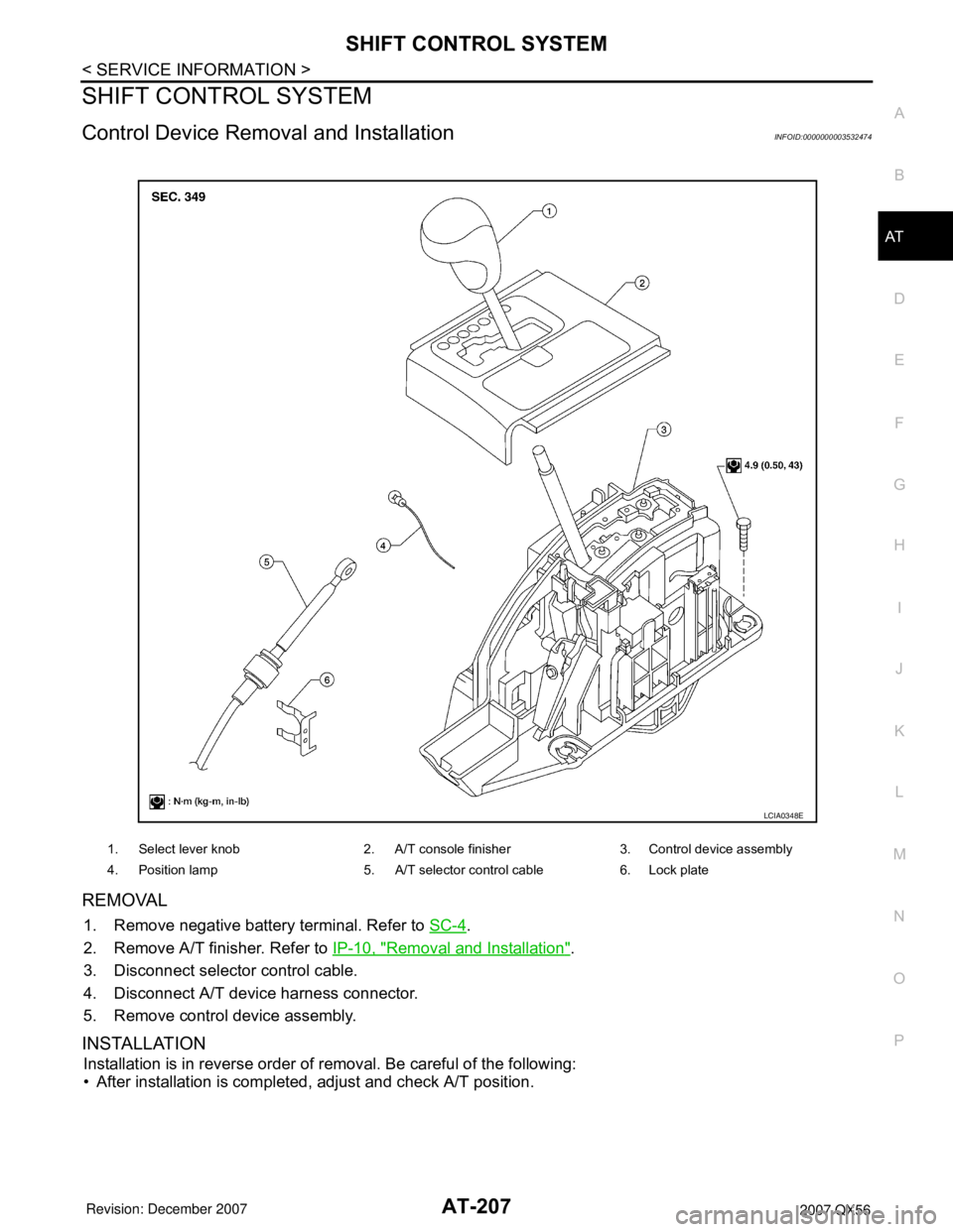
Control Device Removal and InstallationINFOID:0000000003532474
REMOVAL
1. Remove negative battery terminal. Refer to SC-4.
2. Remove A/T finisher. Refer to IP-10, "
Removal and Installation".
3. Disconnect selector control cable.
4. Disconnect A/T device harness connector.
5. Remove control device assembly.
INSTALLATION
Installation is in reverse order of removal. Be careful of the following:
• After installation is completed, adjust and check A/T position.
1. Select lever knob 2. A/T console finisher 3. Control device assembly
4. Position lamp 5. A/T selector control cable 6. Lock plate
LCIA0348E
Page 278 of 3061

AT-208
< SERVICE INFORMATION >
SHIFT CONTROL SYSTEM
Adjustment of A/T Position
INFOID:0000000003532475
1. Loosen nut of control cable.
2. Place PNP switch and selector lever in “P” position.
3. After pushing the control cable in the direction shown with a
force of 9.8 N·m (1kg-m, 2.2 lb-ft), release it. This is in the natu-
ral state, tighten control cable nut to specifications.
Checking of A/T PositionINFOID:0000000003532476
1. Place selector lever in “P” position, and turn ignition switch ON
(engine stop).
2. Make sure selector lever can be shifted to other than “P” position
when brake pedal is depressed. Also make sure selector lever
can be shifted from “P” position only when brake pedal is
depressed.
3. Move the selector lever and check for excessive effort, sticking,
noise or rattle.
4. Confirm the selector lever stops at each position with the feel of
engagement when it is moved through all the positions. Check
whether or not the actual position the selector lever is in
matches the position shown by the shift position indicator and
the transmission body.
5. The method of operating the lever to individual positions correctly should be as shown.
6. Confirm the back-up lamps illuminate only when lever is placed in the “R” position. Confirm the back-up
lamps does not illuminate when selector lever is pushed against “R” position in the “P” or “N” position.
7. Confirm the engine can only be started with the selector lever in the “P” and “N” positions.
8. Make sure transmission is locked completely in “P” position.Control cable nut : 14.5 N·m (1.5 kg-m, 11 ft-lb)
LCIA0345E
LCIA0325E
Page 291 of 3061
AIR BREATHER HOSE
AT-221
< SERVICE INFORMATION >
D
E
F
G
H
I
J
K
L
MA
B
AT
N
O
P
AIR BREATHER HOSE
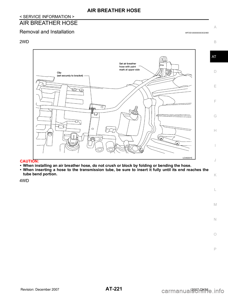
Removal and InstallationINFOID:0000000003532480
2WD
CAUTION:
• When installing an air breather hose, do not crush or block by folding or bending the hose.
• When inserting a hose to the transmission tube, be sure to insert it fully until its end reaches the
tube bend portion.
4WD
LCIA0331E
Page 292 of 3061
AT-222
< SERVICE INFORMATION >
AIR BREATHER HOSE
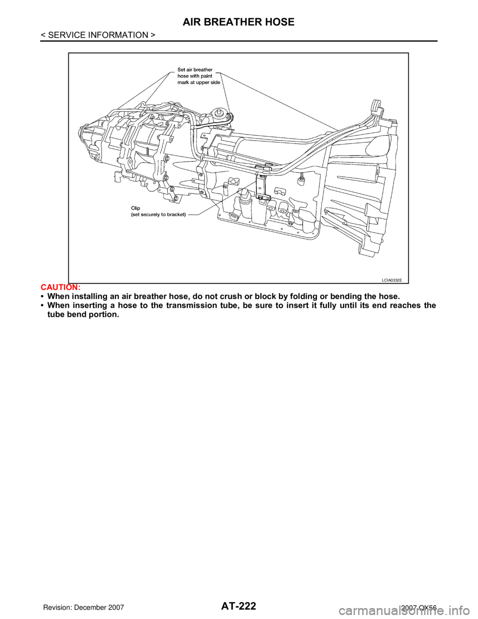
CAUTION:
• When installing an air breather hose, do not crush or block by folding or bending the hose.
• When inserting a hose to the transmission tube, be sure to insert it fully until its end reaches the
tube bend portion.
LCIA0332E
Page 294 of 3061
AT-224
< SERVICE INFORMATION >
TRANSMISSION ASSEMBLY
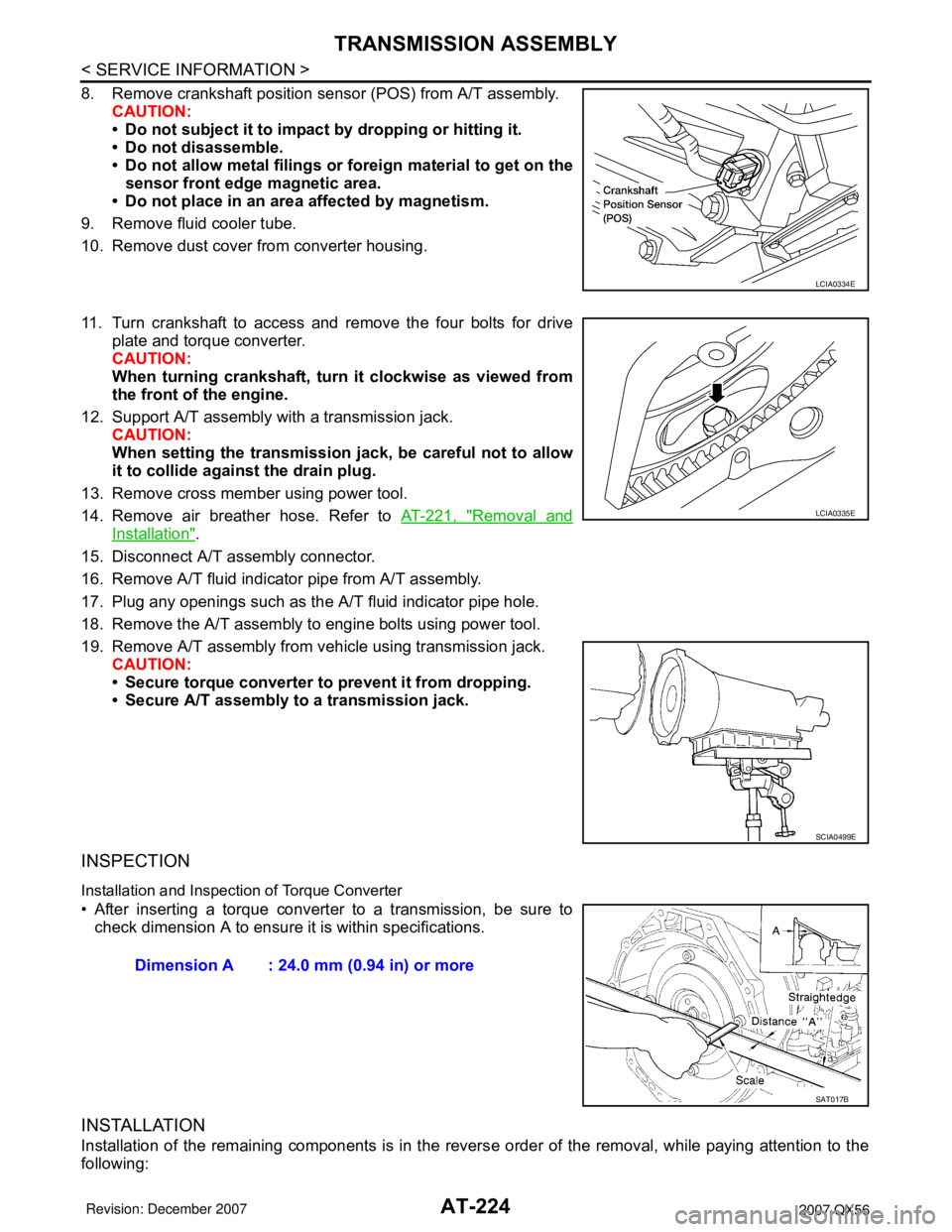
8. Remove crankshaft position sensor (POS) from A/T assembly.
CAUTION:
• Do not subject it to impact by dropping or hitting it.
• Do not disassemble.
• Do not allow metal filings or foreign material to get on the
sensor front edge magnetic area.
• Do not place in an area affected by magnetism.
9. Remove fluid cooler tube.
10. Remove dust cover from converter housing.
11. Turn crankshaft to access and remove the four bolts for drive
plate and torque converter.
CAUTION:
When turning crankshaft, turn it clockwise as viewed from
the front of the engine.
12. Support A/T assembly with a transmission jack.
CAUTION:
When setting the transmission jack, be careful not to allow
it to collide against the drain plug.
13. Remove cross member using power tool.
14. Remove air breather hose. Refer to AT-221, "
Removal and
Installation".
15. Disconnect A/T assembly connector.
16. Remove A/T fluid indicator pipe from A/T assembly.
17. Plug any openings such as the A/T fluid indicator pipe hole.
18. Remove the A/T assembly to engine bolts using power tool.
19. Remove A/T assembly from vehicle using transmission jack.
CAUTION:
• Secure torque converter to prevent it from dropping.
• Secure A/T assembly to a transmission jack.
INSPECTION
Installation and Inspection of Torque Converter
• After inserting a torque converter to a transmission, be sure to
check dimension A to ensure it is within specifications.
INSTALLATION
Installation of the remaining components is in the reverse order of the removal, while paying attention to the
following:
LCIA0334E
LCIA0335E
SCIA0499E
Dimension A : 24.0 mm (0.94 in) or more
SAT017B
Page 295 of 3061
TRANSMISSION ASSEMBLY
AT-225
< SERVICE INFORMATION >
D
E
F
G
H
I
J
K
L
MA
B
AT
N
O
P
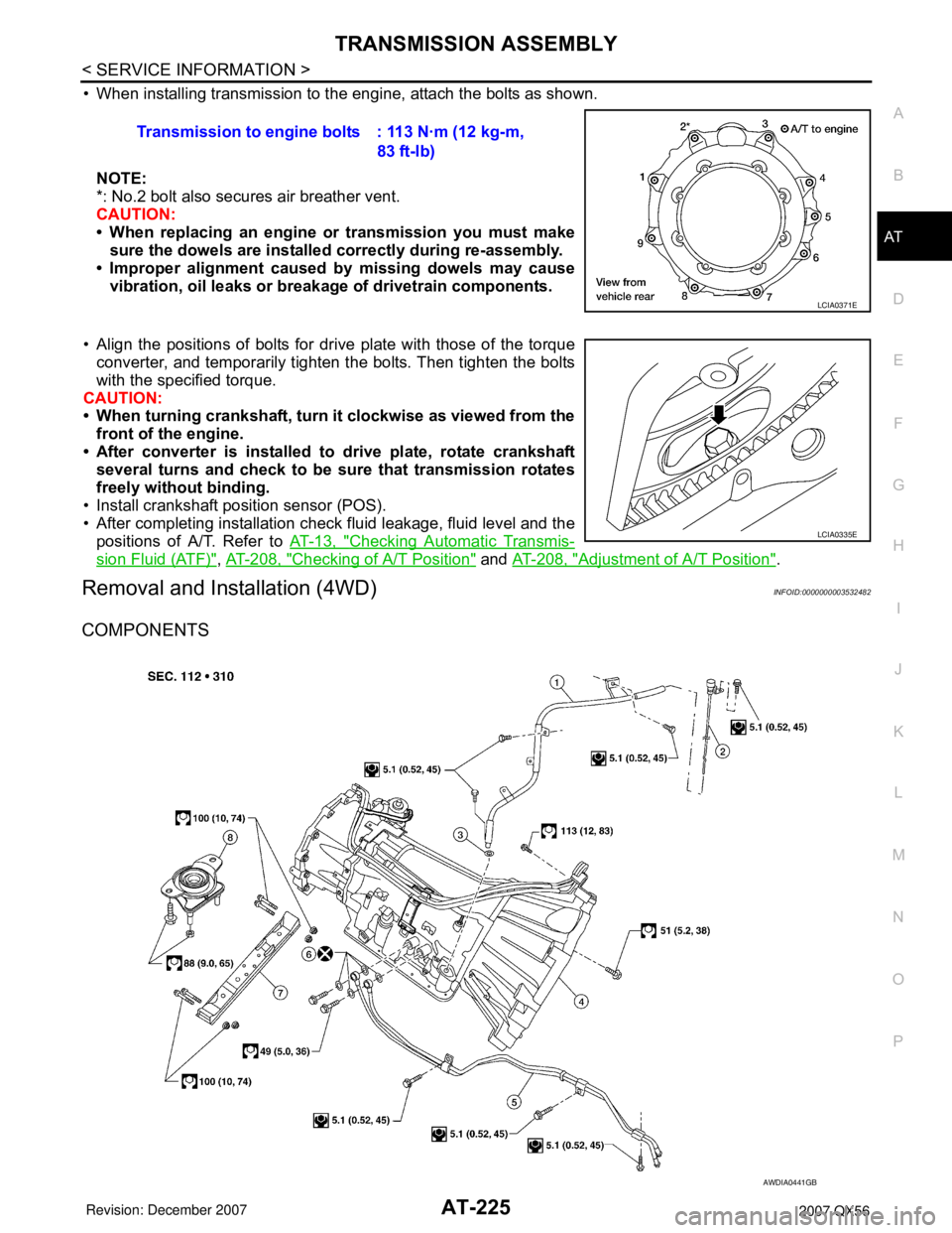
• When installing transmission to the engine, attach the bolts as shown.
NOTE:
*: No.2 bolt also secures air breather vent.
CAUTION:
• When replacing an engine or transmission you must make
sure the dowels are installed correctly during re-assembly.
• Improper alignment caused by missing dowels may cause
vibration, oil leaks or breakage of drivetrain components.
• Align the positions of bolts for drive plate with those of the torque
converter, and temporarily tighten the bolts. Then tighten the bolts
with the specified torque.
CAUTION:
• When turning crankshaft, turn it clockwise as viewed from the
front of the engine.
• After converter is installed to drive plate, rotate crankshaft
several turns and check to be sure that transmission rotates
freely without binding.
• Install crankshaft position sensor (POS).
• After completing installation check fluid leakage, fluid level and the
positions of A/T. Refer to AT-13, "
Checking Automatic Transmis-
sion Fluid (ATF)", AT-208, "Checking of A/T Position" and AT-208, "Adjustment of A/T Position".
Removal and Installation (4WD)INFOID:0000000003532482
COMPONENTS
Transmission to engine bolts : 113 N·m (12 kg-m,
83 ft-lb)
LCIA0371E
LCIA0335E
AWDIA0441GB