engine INFINITI QX56 2007 Factory Service Manual
[x] Cancel search | Manufacturer: INFINITI, Model Year: 2007, Model line: QX56, Model: INFINITI QX56 2007Pages: 3061, PDF Size: 64.56 MB
Page 1885 of 3061
EXHAUST SYSTEMEX-3
< SERVICE INFORMATION >
C
DE
F
G H
I
J
K L
M A
EX
NP
O
EXHAUST SYSTEM
Checking Exhaust SystemINFOID:0000000003532211
Check exhaust pipes, muffler and mounting for improper
attachment, leaks, cracks, damage or deterioration.
• If anything is found, repair or replace damaged parts.
Removal and InstallationINFOID:0000000003532212
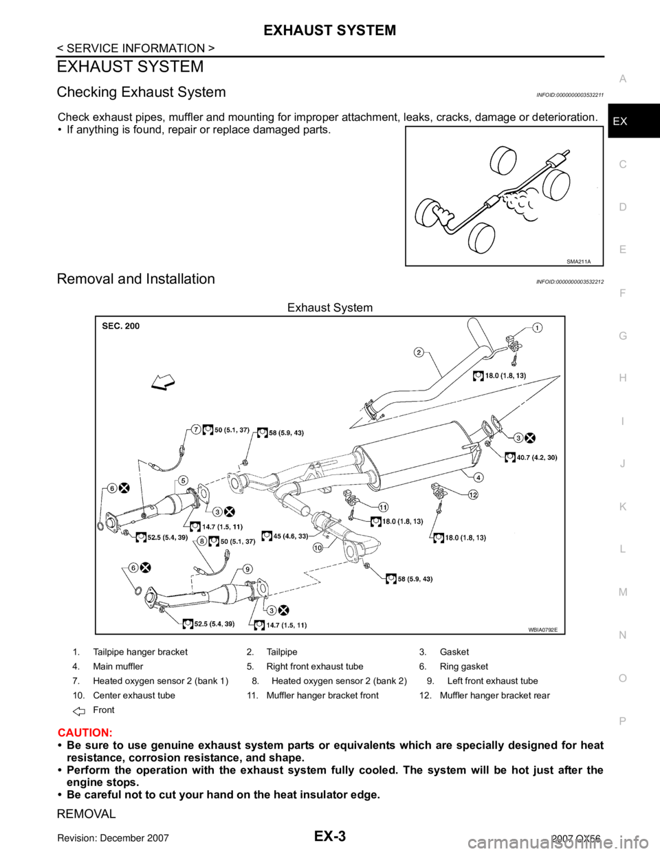
Exhaust System
CAUTION:
• Be sure to use genuine exhaust system parts or equivalents which are specially designed for heat
resistance, corrosion resistance, and shape.
• Perform the operation with the exhaust system full y cooled. The system will be hot just after the
engine stops.
• Be careful not to cut your hand on the heat insulator edge.
REMOVAL
SMA211A
WBIA0792E
1. Tailpipe hanger bracket 2. Tailpipe 3. Gasket
4. Main muffler 5. Right front exhaust tube 6. Ring gasket
7. Heated oxygen sensor 2 (bank 1) 8. Heated oxygen sensor 2 (bank 2) 9. Left front exhaust tube
10. Center exhaust tube 11. Muffler hanger bracket front 12. Muffler hanger bracket rear
Front
Page 1886 of 3061
EX-4
< SERVICE INFORMATION >
EXHAUST SYSTEM
Remove exhaust system components using power tool.
INSTALLATION
Installation is in the reverse order of removal.
CAUTION:
• Always replace exhaust gaskets with new ones when reassembling.
• Before installing a new heated oxygen sensor, clean and lube the exhaust tube threads using Tool.
• Discard any heated oxygen sensor which has been dropped from a height of more than 0.5 m (19.7
in) onto a hard surface such as a concrete floor; replace with a new one.
• Do not over-torque the heated oxygen sensor. Doing so may damage the heated oxygen sensor,
resulting in the MIL coming on.
• If any mounting insulator is badly deformed, repair or replace it. If deposits such as mud pile up on
the mounting insulators, clean and inspect them.
• Temporarily tighten the nuts on the exhaust manifold side and the bolts on the vehicle side. Check
each part for interference with other components, and then tighten the nuts and bolts to specifica-
tion.
INSPECTION AFTER INSTALLATION
• With the engine running, check exhaust tube joints for gas leakage and unusual noises.
• Check to ensure that mounting brackets and mounting rubbers are installed properly and free from undue
stress. Improper installation could result in excessive noise and vibration. Tool number
A : — (J-43897-18)
B : — (J-43897-12)
Page 1891 of 3061
WHEEL HUB
FAX-5
< SERVICE INFORMATION >
C
E
F
G
H
I
J
K
L
MA
B
FA X
N
O
P
WHEEL HUB
On-Vehicle Inspection and ServiceINFOID:0000000003532614
Make sure the mounting conditions (looseness, backlash) of each component and component status (wear,
damage) are normal.
WHEEL BEARING INSPECTION
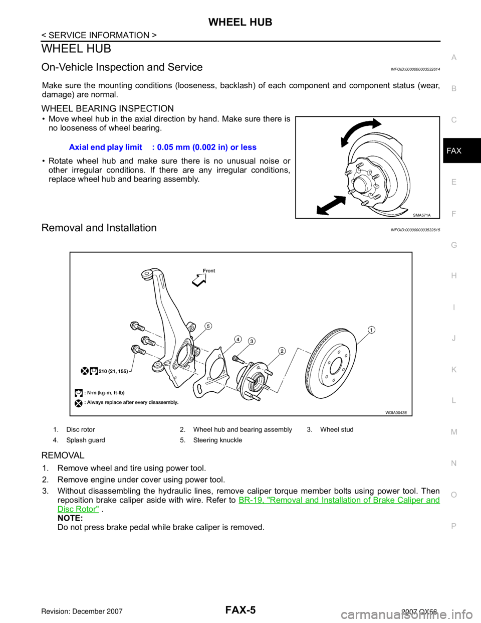
• Move wheel hub in the axial direction by hand. Make sure there is
no looseness of wheel bearing.
• Rotate wheel hub and make sure there is no unusual noise or
other irregular conditions. If there are any irregular conditions,
replace wheel hub and bearing assembly.
Removal and InstallationINFOID:0000000003532615
REMOVAL
1. Remove wheel and tire using power tool.
2. Remove engine under cover using power tool.
3. Without disassembling the hydraulic lines, remove caliper torque member bolts using power tool. Then
reposition brake caliper aside with wire. Refer to BR-19, "
Removal and Installation of Brake Caliper and
Disc Rotor" .
NOTE:
Do not press brake pedal while brake caliper is removed.Axial end play limit : 0.05 mm (0.002 in) or less
SMA571A
1. Disc rotor 2. Wheel hub and bearing assembly 3. Wheel stud
4. Splash guard 5. Steering knuckle
WDIA0043E
Page 1893 of 3061
DRIVE SHAFT
FAX-7
< SERVICE INFORMATION >
C
E
F
G
H
I
J
K
L
MA
B
FA X
N
O
P
DRIVE SHAFT
Removal and InstallationINFOID:0000000003532616
REMOVAL
1. Remove wheel and tire using power tool.
2. Remove engine under cover using power tool.
3. Remove wheel sensor harness from mount on knuckle.
CAUTION:
Do not pull on wheel sensor harness.
4. Without disassembling the hydraulic lines, remove brake caliper using power tool. Reposition it aside with
wire. Refer to BR-19, "
Removal and Installation of Brake Caliper and Disc Rotor" .
NOTE:
Avoid depressing brake pedal while brake caliper is removed.
5. Remove coil spring and shock absorber assembly using power tool. Refer to FSU-10, "
Removal and
Installation" .
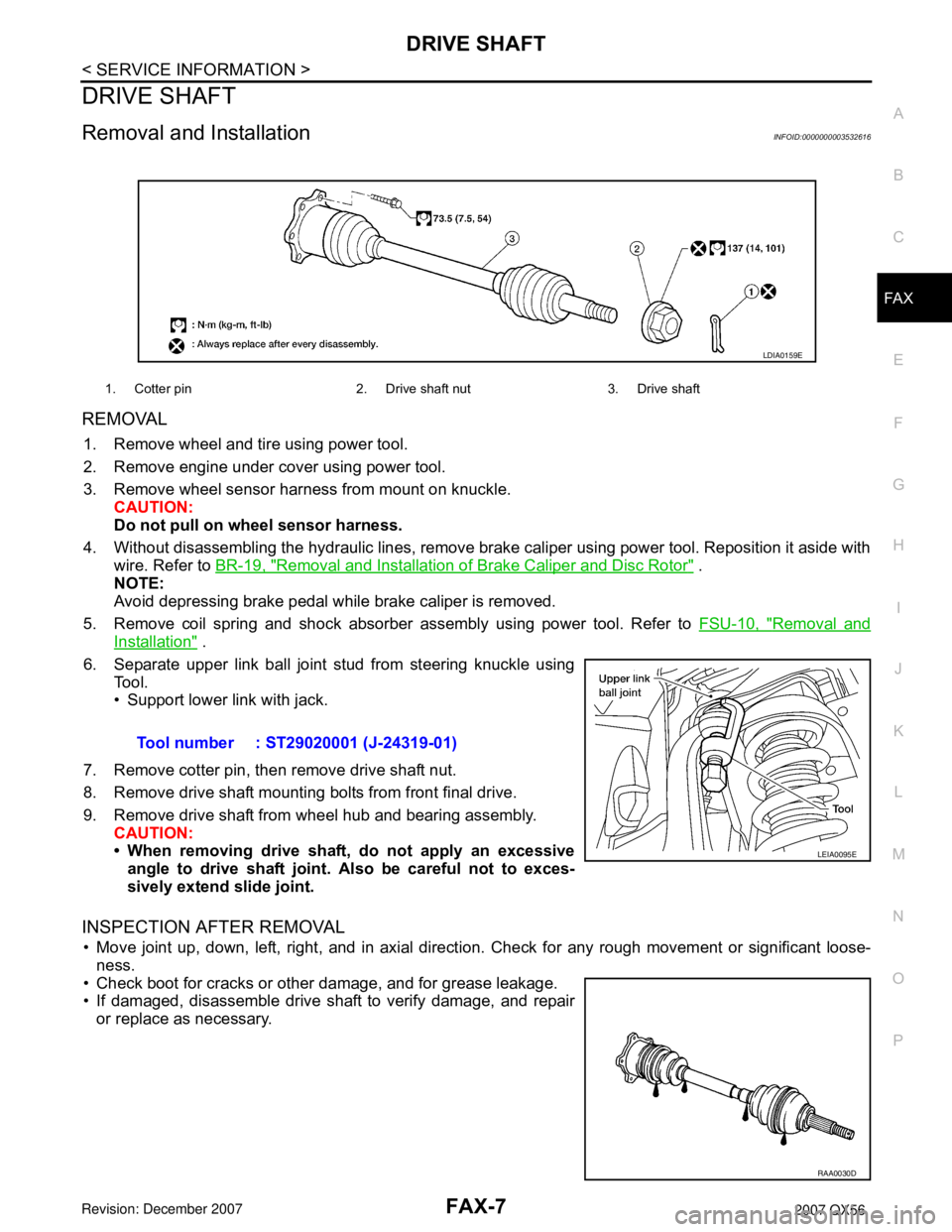
6. Separate upper link ball joint stud from steering knuckle using
Tool.
• Support lower link with jack.
7. Remove cotter pin, then remove drive shaft nut.
8. Remove drive shaft mounting bolts from front final drive.
9. Remove drive shaft from wheel hub and bearing assembly.
CAUTION:
• When removing drive shaft, do not apply an excessive
angle to drive shaft joint. Also be careful not to exces-
sively extend slide joint.
INSPECTION AFTER REMOVAL
• Move joint up, down, left, right, and in axial direction. Check for any rough movement or significant loose-
ness.
• Check boot for cracks or other damage, and for grease leakage.
• If damaged, disassemble drive shaft to verify damage, and repair
or replace as necessary.
1. Cotter pin 2. Drive shaft nut 3. Drive shaft
LDIA0159E
Tool number : ST29020001 (J-24319-01)
LEIA0095E
RAA0030D
Page 1906 of 3061
DIFFERENTIAL GEAR OIL
FFD-7
< SERVICE INFORMATION >
C
E
F
G
H
I
J
K
L
MA
B
FFD
N
O
P
DIFFERENTIAL GEAR OIL
Changing Differential Gear OilINFOID:0000000003532588
DRAINING
1. Stop the engine.
2. Remove the drain plug from the front final drive assembly to drain the differential gear oil.
3. Install the drain plug with sealant applied on the threads to the front final drive assembly. Tighten to the
specified torque. Refer to FFD-13, "
Disassembly and Assembly".
• Use High Performance Thread Sealant or equivalent. Refer to GI-45, "
Recommended Chemical Product
and Sealant".
FILLING
1. Remove the filler plug from the front final drive assembly.
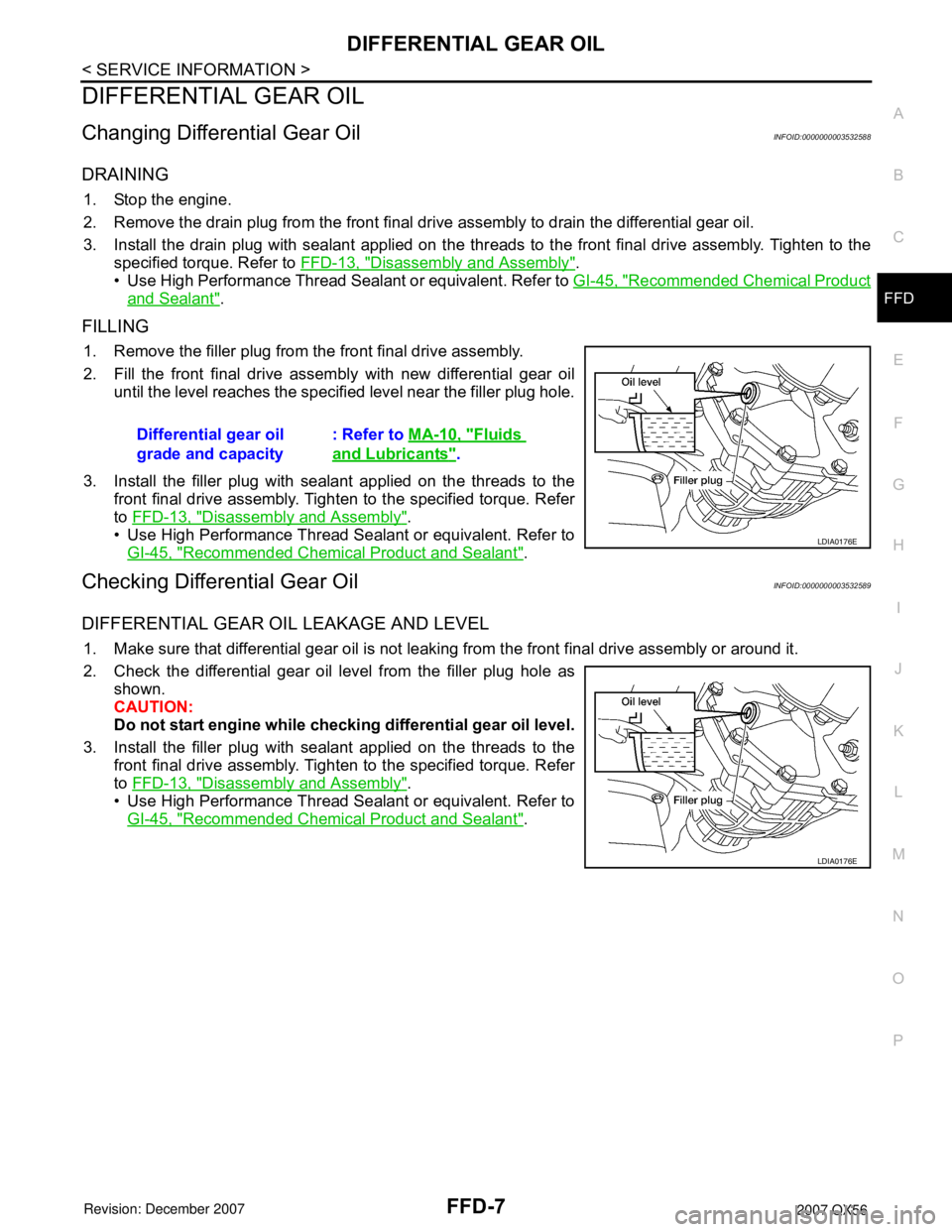
2. Fill the front final drive assembly with new differential gear oil
until the level reaches the specified level near the filler plug hole.
3. Install the filler plug with sealant applied on the threads to the
front final drive assembly. Tighten to the specified torque. Refer
to FFD-13, "
Disassembly and Assembly".
• Use High Performance Thread Sealant or equivalent. Refer to
GI-45, "
Recommended Chemical Product and Sealant".
Checking Differential Gear OilINFOID:0000000003532589
DIFFERENTIAL GEAR OIL LEAKAGE AND LEVEL
1. Make sure that differential gear oil is not leaking from the front final drive assembly or around it.
2. Check the differential gear oil level from the filler plug hole as
shown.
CAUTION:
Do not start engine while checking differential gear oil level.
3. Install the filler plug with sealant applied on the threads to the
front final drive assembly. Tighten to the specified torque. Refer
to FFD-13, "
Disassembly and Assembly".
• Use High Performance Thread Sealant or equivalent. Refer to
GI-45, "
Recommended Chemical Product and Sealant". Differential gear oil
grade and capacity: Refer to MA-10, "
Fluids
and Lubricants".
LDIA0176E
LDIA0176E
Page 1932 of 3061

FL-1
ENGINE
C
D
E
F
G
H
I
J
K
L
M
SECTION FL
A
FL
N
O
P
CONTENTS
FUEL SYSTEM
SERVICE INFORMATION ............................2
PRECAUTIONS ...................................................2
Precaution for Supplemental Restraint System
(SRS) "AIR BAG" and "SEAT BELT PRE-TEN-
SIONER" ...................................................................
2
PREPARATION ...................................................3
Special Service Tool .................................................3
Commercial Service Tool ..........................................3
FUEL SYSTEM ....................................................4
Checking Fuel Line ...................................................4
General Precaution ...................................................4
FUEL LEVEL SENSOR UNIT, FUEL FILTER
AND FUEL PUMP ASSEMBLY .........................
5
Removal and Installation ..........................................5
Disassembly and Assembly ......................................9
FUEL TANK ......................................................10
Removal and Installation .........................................10
SERVICE DATA AND SPECIFICATIONS
(SDS) .................................................................
15
Standard and Limit ..................................................15
Page 1935 of 3061

FL-4
< SERVICE INFORMATION >
FUEL SYSTEM
FUEL SYSTEM
Checking Fuel LineINFOID:0000000003532203
Inspect fuel lines, fuel filler cap and fuel tank for improper attach-
ment, leaks, cracks, damage, loose connections, chafing or deterio-
ration.
If necessary, repair or replace damaged parts.
General PrecautionINFOID:0000000003532204
WARNING:
When replacing fuel line parts, be sure to observe the following.
• Put a “CAUTION: INFLAMMABLE” sign in the workshop.
• Be sure to work in a well ventilated area and furnish workshop with a CO
2 fire extinguisher.
• Do not smoke while servicing fuel system. Keep open flames and sparks away from the work area.
CAUTION:
• Before removing fuel line parts, carry out the following procedures:
- Put drained fuel in an explosion-proof container and put the lid on securely. Keep the container in
safe area.
- Release fuel pressure from the fuel lines. Refer to EC-80, "
Fuel Pressure Check" .
- Disconnect the battery negative terminal.
• Always replace O-rings and clamps with new ones.
• Do not kink or twist hoses when they are being installed.
• After connecting the fuel tube quick connectors, make sure
the quick connectors are secure.
Ensure that the connector and resin tube do not contact any
adjacent parts.
• After installing tubes, make sure there is no fuel leakage at
connections in the following steps.
- Apply fuel pressure to fuel lines with turning ignition switch
ON (with engine stopped). Then check for fuel leaks at con-
nections.
- Start the engine and rev it up and check for fuel leaks at con-
nections.
• Use only a Genuine NISSAN fuel filler cap as a replacement. If
an incorrect fuel filler cap is used, the MIL may come on.
• For servicing “Evaporative Emission System” parts, refer to
EC-33
.
• For servicing “On Board Refueling Vapor Recovery (ORVR)”
parts, refer to EC-40
.
SMA803A
PBIC1268E
Page 1939 of 3061

FL-8
< SERVICE INFORMATION >
FUEL LEVEL SENSOR UNIT, FUEL FILTER AND FUEL PUMP ASSEMBLY
12. Remove the lock ring using Tool.
13. Remove the fuel level sensor, fuel filter, and fuel pump assem-
bly. Remove and discard the fuel level sensor, fuel filter, and fuel
pump assembly O-ring.
CAUTION:
• Do not bend the float arm during removal.
• Avoid impacts such as dropping when handling the com-
ponents.
INSTALLATION
Installation is in the reverse order of removal.
• For installation, use a new fuel level sensor, fuel filter, and fuel pump assembly O-ring.
• Connect the quick connector as follows:
- Check the connection for any damage or foreign materials.
- Align the connector with the pipe, then insert the connector straight into the pipe until a click is heard.
- After connecting the quick connector, make sure that the connec-
tion is secure by checking as follows:
- Pull the tube and the connector to make sure they are securely
connected.
- Visually inspect the connector to make sure the two retainer tabs
are securely connected.
INSPECTION AFTER INSTALLATION
1. Turn the ignition switch ON but do not start engine, then check the fuel pipes and hose connections for
leaks while applying fuel pressure to the system.
2. Start the engine and rev it above idle speed, then check that there are no fuel leaks at any of the fuel pipe
and hose connections.Tool number : — (J-46536)
LBIA0389E
PBIC1653E
Page 1945 of 3061

FL-14
< SERVICE INFORMATION >
FUEL TANK
INSPECTION AFTER INSTALLATION
1. Turn the ignition switch ON but do not start engine, then check the fuel pipe and hose connections for
leaks while applying fuel pressure.
2. Start the engine and rev it above idle, then check that there are no fuel leaks at any of the fuel pipe and
hose connections.
Page 1948 of 3061
FSU-2
< SERVICE INFORMATION >
PRECAUTIONS
SERVICE INFORMATION
PRECAUTIONS
PrecautionINFOID:0000000003532631
• When installing the rubber bushings, the final tightening must be done under unladen condition and with the
tires on level ground. Oil will shorten the life of the rubber bushings, so wipe off any spilled oil immediately.
• Unladen condition means the fuel tank, engine coolant and lubricants are at the full specification. The spare
tire, jack, hand tools, and mats are in their designated positions.
• After installing suspension components, check the wheel alignment.
• Lock nuts are not reusable. Always use new lock nuts for installation. New lock nuts are pre-oiled, do not
apply any additional lubrication.