air condition INFINITI QX56 2007 Factory Service Manual
[x] Cancel search | Manufacturer: INFINITI, Model Year: 2007, Model line: QX56, Model: INFINITI QX56 2007Pages: 3061, PDF Size: 64.56 MB
Page 1 of 3061
-1
QUICK REFERENCE INDEX
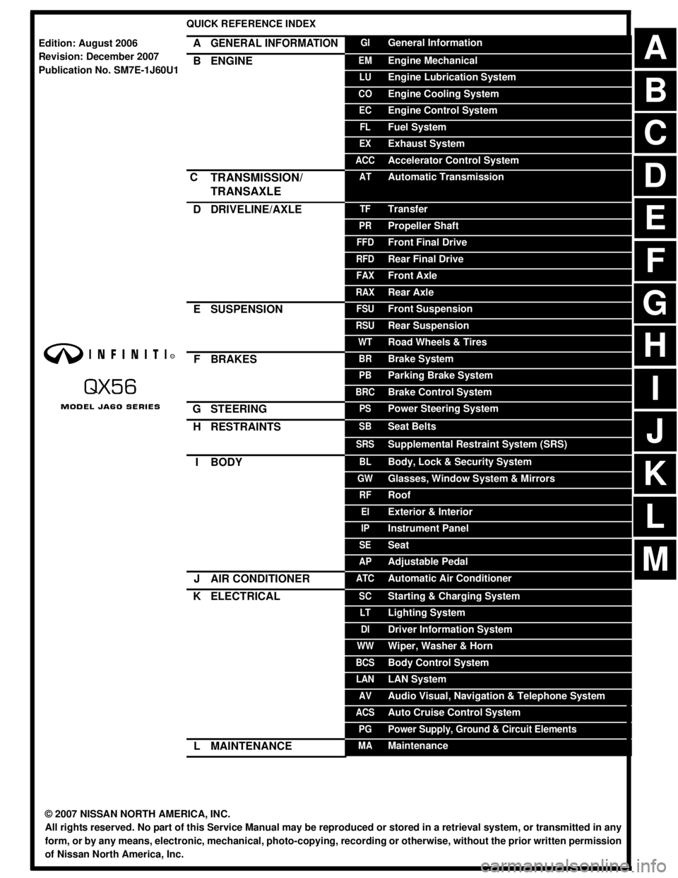
AGENERAL INFORMATIONGIGeneral Information
BENGINEEMEngine Mechanical
LUEngine Lubrication System
COEngine Cooling System
ECEngine Control System
FLFuel System
EXExhaust System
ACCAccelerator Control System
CTRANSMISSION/
TRANSAXLEATAutomatic Transmission
DDRIVELINE/AXLETFTransfer
PRPropeller Shaft
FFDFront Final Drive
RFDRear Final Drive
FAXFront Axle
RAXRear Axle
ESUSPENSIONFSUFront Suspension
RSURear Suspension
WTRoad Wheels & Tires
FBRAKESBRBrake System
PBParking Brake System
BRCBrake Control System
GSTEERINGPSPower Steering System
HRESTRAINTSSBSeat Belts
SRSSupplemental Restraint System (SRS)
IBODYBLBody, Lock & Security System
GWGlasses, Window System & Mirrors
RFRoof
EIExterior & Interior
IPInstrument Panel
SESeat
APAdjustable Pedal
JAIR CONDITIONERATCAutomatic Air Conditioner
KELECTRICALSCStarting & Charging System
LTLighting System
DIDriver Information System
WWWiper, Washer & Horn
BCSBody Control System
LANLAN System
AVAudio Visual, Navigation & Telephone System
ACSAuto Cruise Control System
PGPower Supply, Ground & Circuit Elements
LMAINTENANCEMAMaintenance
Edition: August 2006
Revision: December 2007
Publication No. SM7E-1J60U1
B
D
© 2007 NISSAN NORTH AMERICA, INC.
All rights reserved. No part of this Service Manual may be reproduced or stored in a retrieval system, or transmitted in any
form, or by any means, electronic, mechanical, photo-copying, recording or otherwise, without the prior written permission
of Nissan North America, Inc.
A
C
E
F
G
H
I
J
K
L
M
Page 8 of 3061
QUICK REFERENCE CHART: QX56
2007
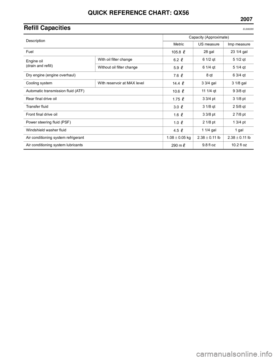
Refill CapacitiesELS00295
DescriptionCapacity (Approximate)
Metric US measure Imp measure
Fuel 105.8 28 gal 23 1/4 gal
Engine oil
(drain and refill) With oil filter change
6.2 6 1/2 qt 5 1/2 qt
Without oil filter change 5.9 6 1/4 qt 5 1/4 qt
Dry engine (engine overhaul) 7.6 8 qt 6 3/4 qt
Cooling system With reservoir at MAX level 14.4 3 3/4 gal 3 1/8 gal
Automatic transmission fluid (ATF) 10.6 11 1/4 qt 9 3/8 qt
Rear final drive oil 1.75 3 3/4 pt 3 1/8 pt
Transfer fluid 3.0 3 1/8 qt 2 5/8 qt
Front final drive oil 1.6 3 3/8 pt 2 7/8 pt
Power steering fluid (PSF) 1.0 2 1/8 pt 1 3/4 pt
Windshield washer fluid 4.5 1 1/4 gal 1 gal
Air conditioning system refrigerant 1.08 ± 0.05 kg 2.38 ± 0.11 lb 2.38 ± 0.11 lb
Air conditioning system lubricants 290 m9.8 fl oz 10.2 fl oz
Page 43 of 3061
![INFINITI QX56 2007 Factory Service Manual ACS-30
< SERVICE INFORMATION >[ICC]
TROUBLE DIAGNOSIS — GENERAL DESCRIPTION
• Touch “ON” and “OFF” to check that the stop lamps operate as in
the following chart.
BOOSTER SOL/V 3
• Touch INFINITI QX56 2007 Factory Service Manual ACS-30
< SERVICE INFORMATION >[ICC]
TROUBLE DIAGNOSIS — GENERAL DESCRIPTION
• Touch “ON” and “OFF” to check that the stop lamps operate as in
the following chart.
BOOSTER SOL/V 3
• Touch](/img/42/57029/w960_57029-42.png)
ACS-30
< SERVICE INFORMATION >[ICC]
TROUBLE DIAGNOSIS — GENERAL DESCRIPTION
• Touch “ON” and “OFF” to check that the stop lamps operate as in
the following chart.
BOOSTER SOL/V 3
• Touch any of “MODE 1”, “MODE 2”, “MODE 3” to check that follow-
ing operation condition is caused by operating monitor and brake
pedal.
• “START” is displayed 10 seconds after operation start. (Active test
is completed.)
Self-Diagnostic FunctionINFOID:0000000003533793
WITH CONSULT-II
1. Go to operation check after asking the customer for symptom information. Refer to ACS-9 .
2. Stop vehicle, turn ignition switch OFF, then connect CONSULT-II and CONSULT-II CONVERTER to data
link connector.
3. With engine started, touch “START”, “ICC”, “SELF-DIAG RESULTS” on CONSULT-II screen in this order.
CAUTION:
If “ICC” cannot be shown after several attempts, the ICC unit may be malfunctioning and should
be replaced. Refer to ACS-55
.
4. Self-diagnostic result appears on screen. If “NO DTC ···” is shown, check ICC warning lamp. If any mal-
function is indicated, GO TO step 5.
5. Refer to ACS-34, "
Diagnostic Trouble Code (DTC) Chart", perform appropriate check, and repair or
replace malfunctioning part as necessary.
6. Turn ignition switch OFF.
7. Start engine and touch “START”, “ICC”, “SELF-DIAG RESULTS”, and “ERASE” on CONSULT-II.
CAUTION:
DTC of an existing malfunction will not erase. If the memory does not erase, GO TO step 5.
8. Perform ICC system running test (drive vehicle with ICC system ON), and make sure that ICC warning
lamp does not illuminate.
WITHOUT CONSULT-II
STOP LAMP ON OFF
Stop lamp Lamp ON Lamp OFF
SKIA1232E
SKIA1233E
PKIA0363J
Page 65 of 3061
![INFINITI QX56 2007 Factory Service Manual ACS-52
< SERVICE INFORMATION >[ICC]
TROUBLE DIAGNOSIS FOR SYMPTOMS
• When depressing the accelerator.
• Chime does not sound when the vehicle is not driving.
• Chime does not sound when the syst INFINITI QX56 2007 Factory Service Manual ACS-52
< SERVICE INFORMATION >[ICC]
TROUBLE DIAGNOSIS FOR SYMPTOMS
• When depressing the accelerator.
• Chime does not sound when the vehicle is not driving.
• Chime does not sound when the syst](/img/42/57029/w960_57029-64.png)
ACS-52
< SERVICE INFORMATION >[ICC]
TROUBLE DIAGNOSIS FOR SYMPTOMS
• When depressing the accelerator.
• Chime does not sound when the vehicle is not driving.
• Chime does not sound when the system does not detect any vehicle ahead. Diagnose the conditions under
which the system is detecting the vehicle ahead and when the system is malfunctioning. If there is any mal-
function in detecting the vehicle ahead. Refer to ACS-52, "
Symptom 7 the ICC System Frequently Cannot
Detect the Vehicle Ahead/The Detection Zone Is Short".
1.CHECK ICC WARNING CHIME
With CONSULT-II
1. With "ACTIVE TEST" on the CONSULT-II, check that ICC warning chime operates normally.
OK or NG
OK >> Determine preceding vehicle detection status when malfunction occurred. If chime should have
sounded replace ICC unit. Refer to ACS-55, "
ICC Unit". Perform ICC system running test. Refer
to ACS-9, "
ICC System Running Test". Then perform self-diagnosis of ICC system again.
NG >> GO TO 2.
2.CAN COMMUNICATION INSPECTION
With CONSULT-II
1. With CONSULT-II self-diagnosis, check “CAN COMM CIRCUIT”.
OK or NG
OK >> Refer to ACS-37, "DTC 20 CAN COMM CIRCUIT".
NG >> Replace combination meter. Refer to DI-21, "
Removal and Installation of Combination Meter".
Erase DTC and perform ICC system running test. Refer to ACS-9, "
ICC System Running Test".
Then perform self-diagnosis of ICC system again.
Symptom 6 Driving Force Is HuntingINFOID:0000000003533820
1.CHECK ECM
1. Perform self-diagnosis of ECM.
OK or NG
OK >> Refer to ACS-52, "Symptom 7 the ICC System Frequently Cannot Detect the Vehicle Ahead/The
Detection Zone Is Short".
NG >> Repair as necessary. Erase DTC and perform ICC system running test. Refer to ACS-9, "
ICC
System Running Test". Then perform self-diagnosis of ICC system again.
Symptom 7 the ICC System Frequently Cannot Detect the Vehicle Ahead/The Detec-
tion Zone Is Short
INFOID:0000000003533821
The detection function may become disrupted in the following cases:
• When the reflector of the vehicle ahead is small or not clean enough to reflect the laser.
• When driving a road with extremely sharp corners.
• When the laser cannot detect the reflector of the vehicle ahead as the vehicle ahead is passing a hill or
passing the peak.
1.VISUAL CHECK
1. Check ICC sensor body window for contamination and foreign materials.
OK or NG
OK >> If any contamination or foreign materials are found, remove them. Then perform ICC system run-
ning test. Refer to ACS-9, "
ICC System Running Test".
NG >> GO TO 2.
2.CHECK FUNCTION
1. After performing laser beam aiming adjustment, perform ICC system running test. Refer to ACS-9, "
ICC
System Running Test". Check that preceding vehicle detection performance has been improved.
OK or NG
OK >> Inspection End.
NG >> • Replace ICC sensor and perform laser beam aiming adjustment. Refer to ACS-55, "
ICC Sen-
sor".
Page 74 of 3061

AT-4
DTC Confirmation Procedure ................................152
Diagnosis Procedure .............................................152
DTC P1845 ATF PRESSURE SWITCH 5 ........154
Description .............................................................154
CONSULT-II Reference Value in Data Monitor
Mode ......................................................................
154
On Board Diagnosis Logic .....................................154
Possible Cause ......................................................154
DTC Confirmation Procedure ................................154
Diagnosis Procedure .............................................154
DTC P1846 ATF PRESSURE SWITCH 6 ........156
Description .............................................................156
CONSULT-II Reference Value in Data Monitor
Mode ......................................................................
156
On Board Diagnosis Logic .....................................156
Possible Cause ......................................................156
DTC Confirmation Procedure ................................156
Diagnosis Procedure .............................................156
MAIN POWER SUPPLY AND GROUND CIR-
CUIT .................................................................
158
Wiring Diagram - AT - MAIN ..................................158
Diagnosis Procedure .............................................159
CLOSED THROTTLE POSITION AND WIDE
OPEN THROTTLE POSITION CIRCUIT .........
161
CONSULT-II Reference Value in Data Monitor
Mode ......................................................................
161
Diagnosis Procedure .............................................161
BRAKE SIGNAL CIRCUIT ..............................162
CONSULT-II Reference Value in Data Monitor
Mode ......................................................................
162
Diagnosis Procedure .............................................162
TOW MODE SWITCH ......................................163
Description .............................................................163
Wiring Diagram - AT - TMSW ................................163
Diagnosis Procedure .............................................164
TROUBLE DIAGNOSIS FOR SYMPTOMS .....165
Wiring Diagram - AT - NONDTC ............................165
A/T Check Indicator Lamp Does Not Come On .....167
Engine Cannot Be Started in "P" or "N" Position ...168
In "P" Position, Vehicle Moves When Pushed .......168
In "N" Position, Vehicle Moves ..............................169
Large Shock ("N" to "D" Position) ..........................170
Vehicle Does Not Creep Backward in "R" Position ..172
Vehicle Does Not Creep Forward in "D" Position ..175
Vehicle Cannot Be Started from D1 .......................177
A/T Does Not Shift: D1→ D2 ..................................179
A/T Does Not Shift: D2→ D3 ..................................181
A/T Does Not Shift: D3→ D4 ..................................183
A/T Does Not Shift: D4→ D5 ..................................185
A/T Does Not Perform Lock-up .............................187
A/T Does Not Hold Lock-up Condition ...................189
Lock-up Is Not Released .......................................190
Engine Speed Does Not Return to Idle .................191
A/T Does Not Shift: 5th gear → 4th gear ..............192
A/T Does Not Shift: 4th gear → 3rd gear ..............194
A/T Does Not Shift: 3rd gear → 2nd gear .............196
A/T Does Not Shift: 2nd gear → 1st gear .............197
Vehicle Does Not Decelerate By Engine Brake ....199
A/T SHIFT LOCK SYSTEM ..............................202
Description ............................................................202
Shift Lock System Electrical Parts Location ..........202
Wiring Diagram - AT - SHIFT ................................203
Shift Lock Control Unit Reference Value ..............204
Component Inspection ..........................................204
SHIFT CONTROL SYSTEM .............................207
Control Device Removal and Installation ..............207
Adjustment of A/T Position ....................................208
Checking of A/T Position .......................................208
ON-VEHICLE SERVICE ...................................209
Oil Pan ..................................................................209
Control Valve with TCM and A/T Fluid Tempera-
ture Sensor 2 ........................................................
210
Rear Oil Seal .........................................................219
AIR BREATHER HOSE ....................................221
Removal and Installation .......................................221
TRANSMISSION ASSEMBLY ..........................223
Removal and Installation (2WD) ...........................223
Removal and Installation (4WD) ...........................225
OVERHAUL ......................................................228
Component ...........................................................228
Oil Channel ...........................................................235
Location of Adjusting Shims, Needle Bearings,
Thrust Washers and Snap Rings ..........................
237
DISASSEMBLY ................................................240
Disassembly ..........................................................240
REPAIR FOR COMPONENT PARTS ..............258
Oil Pump ...............................................................258
Front Sun Gear, 3rd One-Way Clutch ...................260
Front Carrier, Input Clutch, Rear Internal Gear .....262
Mid Sun Gear, Rear Sun Gear, High and Low Re-
verse Clutch Hub ..................................................
267
High and Low Reverse Clutch ..............................272
Direct Clutch .........................................................274
ASSEMBLY ......................................................277
Assembly (1) .........................................................277
Adjustment ............................................................290
Assembly (2) .........................................................292
SERVICE DATA AND SPECIFICATIONS
(SDS) ................................................................
298
General Specification ............................................298
Vehicle Speed When Shifting Gears .....................298
Vehicle Speed When Performing and Releasing
Complete Lock-up .................................................
299
Stall Speed ............................................................299
Page 85 of 3061
A/T FLUID
AT-15
< SERVICE INFORMATION >
D
E
F
G
H
I
J
K
L
MA
B
AT
N
O
P
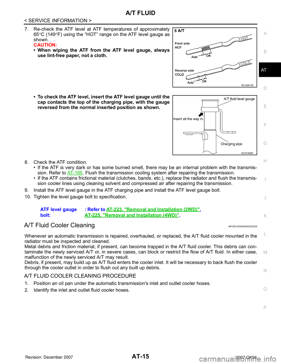
7. Re-check the ATF level at ATF temperatures of approximately
65°C (149°F) using the “HOT” range on the ATF level gauge as
shown.
CAUTION:
• When wiping the ATF from the ATF level gauge, always
use lint-free paper, not a cloth.
• To check the ATF level, insert the ATF level gauge until the
cap contacts the top of the charging pipe, with the gauge
reversed from the normal inserted position as shown.
8. Check the ATF condition.
• If the ATF is very dark or has some burned smell, there may be an internal problem with the transmis-
sion. Refer to AT-165
. Flush the transmission cooling system after repairing the transmission.
• If the ATF contains frictional material (clutches, bands, etc.), replace the radiator and flush the transmis-
sion cooler lines using cleaning solvent and compressed air after repairing the transmission.
9. Install the ATF level gauge in the ATF charging pipe and install the ATF level gauge bolt.
10. Tighten the level gauge bolt to specification.
A/T Fluid Cooler CleaningINFOID:0000000003532226
Whenever an automatic transmission is repaired, overhauled, or replaced, the A/T fluid cooler mounted in the
radiator must be inspected and cleaned.
Metal debris and friction material, if present, can become trapped in the A/T fluid cooler. This debris can con-
taminate the newly serviced A/T or, in severe cases, can block or restrict the flow of A/T fluid. In either case,
malfunction of the newly serviced A/T may result.
Debris, if present, may build up as A/T fluid enters the cooler inlet. It will be necessary to back flush the cooler
through the cooler outlet in order to flush out any built up debris.
A/T FLUID COOLER CLEANING PROCEDURE
1. Position an oil pan under the automatic transmission's inlet and outlet cooler hoses.
2. Identify the inlet and outlet fluid cooler hoses.
WLIA0014E
SCIA1684E
ATF level gauge
bolt:: Refer to AT-223, "Removal and Installation (2WD)",
AT-225, "
Removal and Installation (4WD)".
Page 113 of 3061
TROUBLE DIAGNOSIS
AT-43
< SERVICE INFORMATION >
D
E
F
G
H
I
J
K
L
MA
B
AT
N
O
P
TROUBLE DIAGNOSIS
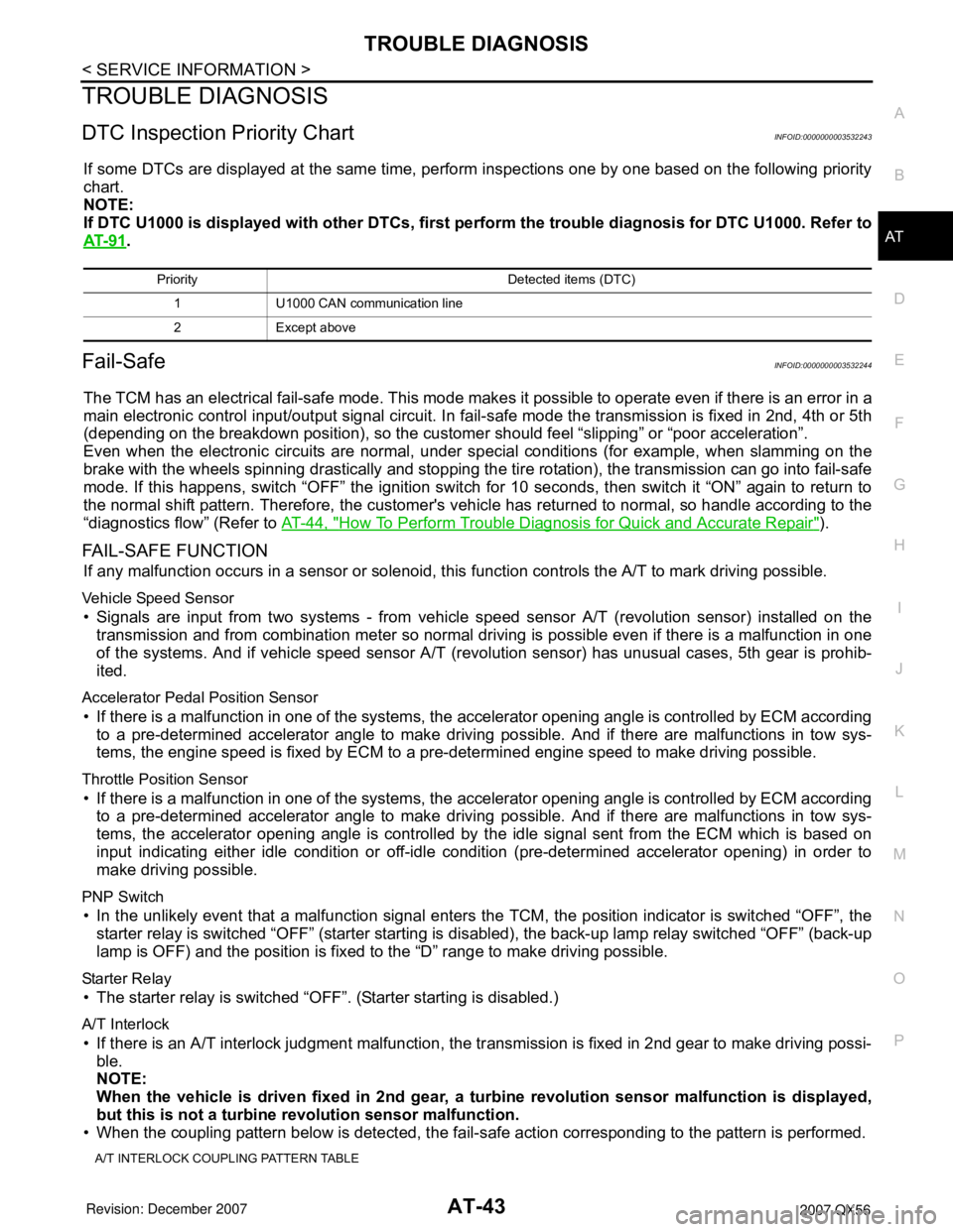
DTC Inspection Priority ChartINFOID:0000000003532243
If some DTCs are displayed at the same time, perform inspections one by one based on the following priority
chart.
NOTE:
If DTC U1000 is displayed with other DTCs, first perform the trouble diagnosis for DTC U1000. Refer to
AT- 9 1
.
Fail-SafeINFOID:0000000003532244
The TCM has an electrical fail-safe mode. This mode makes it possible to operate even if there is an error in a
main electronic control input/output signal circuit. In fail-safe mode the transmission is fixed in 2nd, 4th or 5th
(depending on the breakdown position), so the customer should feel “slipping” or “poor acceleration”.
Even when the electronic circuits are normal, under special conditions (for example, when slamming on the
brake with the wheels spinning drastically and stopping the tire rotation), the transmission can go into fail-safe
mode. If this happens, switch “OFF” the ignition switch for 10 seconds, then switch it “ON” again to return to
the normal shift pattern. Therefore, the customer's vehicle has returned to normal, so handle according to the
“diagnostics flow” (Refer to AT-44, "
How To Perform Trouble Diagnosis for Quick and Accurate Repair").
FAIL-SAFE FUNCTION
If any malfunction occurs in a sensor or solenoid, this function controls the A/T to mark driving possible.
Vehicle Speed Sensor
• Signals are input from two systems - from vehicle speed sensor A/T (revolution sensor) installed on the
transmission and from combination meter so normal driving is possible even if there is a malfunction in one
of the systems. And if vehicle speed sensor A/T (revolution sensor) has unusual cases, 5th gear is prohib-
ited.
Accelerator Pedal Position Sensor
• If there is a malfunction in one of the systems, the accelerator opening angle is controlled by ECM according
to a pre-determined accelerator angle to make driving possible. And if there are malfunctions in tow sys-
tems, the engine speed is fixed by ECM to a pre-determined engine speed to make driving possible.
Throttle Position Sensor
• If there is a malfunction in one of the systems, the accelerator opening angle is controlled by ECM according
to a pre-determined accelerator angle to make driving possible. And if there are malfunctions in tow sys-
tems, the accelerator opening angle is controlled by the idle signal sent from the ECM which is based on
input indicating either idle condition or off-idle condition (pre-determined accelerator opening) in order to
make driving possible.
PNP Switch
• In the unlikely event that a malfunction signal enters the TCM, the position indicator is switched “OFF”, the
starter relay is switched “OFF” (starter starting is disabled), the back-up lamp relay switched “OFF” (back-up
lamp is OFF) and the position is fixed to the “D” range to make driving possible.
Starter Relay
• The starter relay is switched “OFF”. (Starter starting is disabled.)
A/T Interlock
• If there is an A/T interlock judgment malfunction, the transmission is fixed in 2nd gear to make driving possi-
ble.
NOTE:
When the vehicle is driven fixed in 2nd gear, a turbine revolution sensor malfunction is displayed,
but this is not a turbine revolution sensor malfunction.
• When the coupling pattern below is detected, the fail-safe action corresponding to the pattern is performed.
A/T INTERLOCK COUPLING PATTERN TABLE
Priority Detected items (DTC)
1 U1000 CAN communication line
2 Except above
Page 114 of 3061

AT-44
< SERVICE INFORMATION >
TROUBLE DIAGNOSIS
l: NG X: OK
A/T 1st Engine Braking
• When there is an A/T first gear engine brake judgment malfunction, the low coast brake solenoid is switched
“OFF” to avoid the engine brake operation.
Line Pressure Solenoid
• The solenoid is switched “OFF” and the line pressure is set to the maximum hydraulic pressure to make driv-
ing possible.
Torque Converter Clutch Solenoid
• The solenoid is switched “OFF” to release the lock-up.
Low Coast Brake Solenoid
• When a (electrical or functional) malfunction occurs, in order to make driving possible, the engine brake is
not applied in 1st and 2nd gear.
Input Clutch Solenoid
• If a (electrical or functional) malfunction occurs with the solenoid either “ON” or “OFF”, the transmission is
held in 4th gear to make driving possible.
Direct Clutch Solenoid
• If a (electrical or functional) malfunction occurs with the solenoid either “ON” or “OFF”, the transmission is
held in 4th gear to make driving possible.
Front Brake Solenoid
• If a (electrical or functional) malfunction occurs with the solenoid “ON”, in order to make driving possible, the
A/T is held in 5th gear; if the solenoid is OFF, 4th gear.
High and Low Reverse Clutch Solenoid
• If a (electrical or functional) malfunction occurs with the solenoid either “ON” or “OFF”, the transmission is
held in 4th gear to make driving possible.
Turbine Revolution Sensor 1 or 2
• The control is the same as if there were no turbine revolution sensors, 5th gear is prohibited.
How To Perform Trouble Diagnosis for Quick and Accurate RepairINFOID:0000000003532245
INTRODUCTION
The TCM receives a signal from the vehicle speed sensor, accelerator pedal position sensor (throttle position
sensor) or PNP switch and provides shift control or lock-up control via A/T solenoid valves.
The TCM also communicates with the ECM by means of a signal
sent from sensing elements used with the OBD-related parts of the
A/T system for malfunction-diagnostic purposes. The TCM is capa-
ble of diagnosing malfunctioning parts while the ECM can store mal-
functions in its memory.
Input and output signals must always be correct and stable in the
operation of the A/T system. The A/T system must be in good oper-
ating condition and be free of valve seizure, solenoid valve malfunc-
tion, etc.
Gear positionATF pressure switch output
Fail-safe
functionClutch pressure output pattern after fail-safe func-
tion
SW3
(I/C)SW6
(HLR/
C)SW5
(D/C)SW1
(FR/B)SW2
(LC/B)I/C HLR/C D/C FR/B LC/B L/U
A/T interlock
coupling pat-
tern3rd – X X – lHeld in
2nd gearOFF OFF ON OFF OFF OFF
4th – X X –lHeld in
2nd gearOFF OFF ON OFF OFF OFF
5th X X – XlHeld in
2nd gearOFF OFF ON OFF OFF OFF
SAT631IB
Page 154 of 3061
AT-84
< SERVICE INFORMATION >
TROUBLE DIAGNOSIS
CONSULT-II START PROCEDURE
Refer to GI-36, "CONSULT-II Start Procedure".
SELF-DIAGNOSTIC RESULT MODE
Operation Procedure
After performing SELF-DIAGNOSTIC RESULT MODE, place check marks for results on the AT-44, "How To
Perform Trouble Diagnosis for Quick and Accurate Repair". Reference pages are provided following the items.
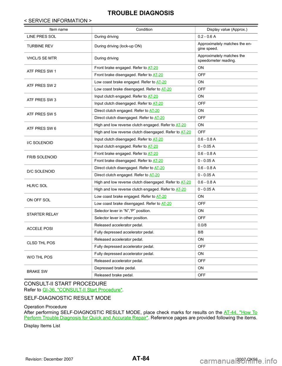
Display Items List
LINE PRES SOL During driving 0.2 - 0.6 A
TURBINE REV During driving (lock-up ON)Approximately matches the en-
gine speed.
VHCL/S SE·MTR During drivingApproximately matches the
speedometer reading.
ATF PRES SW 1Front brake engaged. Refer to AT- 2 0
ON
Front brake disengaged. Refer to AT- 2 0
OFF
ATF PRES SW 2Low coast brake engaged. Refer to AT- 2 0
ON
Low coast brake disengaged. Refer to AT- 2 0
OFF
ATF PRES SW 3Input clutch engaged. Refer to AT- 2 0
ON
Input clutch disengaged. Refer to AT- 2 0
OFF
ATF PRES SW 5Direct clutch engaged. Refer to AT- 2 0
ON
Direct clutch disengaged. Refer to AT- 2 0
OFF
ATF PRES SW 6High and low reverse clutch engaged. Refer to AT- 2 0
ON
High and low reverse clutch disengaged. Refer to AT- 2 0
OFF
I/C SOLENOIDInput clutch disengaged. Refer to AT- 2 0
0.6 - 0.8 A
Input clutch engaged. Refer to AT- 2 0
0 - 0.05 A
FR/B SOLENOIDFront brake engaged. Refer to AT- 2 0
0.6 - 0.8 A
Front brake disengaged. Refer to AT- 2 0
0 - 0.05 A
D/C SOLENOIDDirect clutch disengaged. Refer to AT- 2 0
0.6 - 0.8 A
Direct clutch engaged. Refer to AT- 2 0
0 - 0.05 A
HLR/C SOLHigh and low reverse clutch disengaged. Refer to AT- 2 0
0.6 - 0.8 A
High and low reverse clutch engaged. Refer to AT- 2 0
0 - 0.05 A
ON OFF SOLLow coast brake engaged. Refer to AT- 2 0
ON
Low coast brake disengaged. Refer to AT- 2 0
OFF
STARTER RELAYSelector lever in “N”,“P” position. ON
Selector lever in other position. OFF
ACCELE POSIReleased accelerator pedal. 0.0/8
Fully depressed accelerator pedal. 8/8
CLSD THL POSReleased accelerator pedal. ON
Fully depressed accelerator pedal. OFF
W/O THL POSFully depressed accelerator pedal. ON
Released accelerator pedal. OFF
BRAKE SWDepressed brake pedal. ON
Released brake pedal. OFF Item name Condition Display value (Approx.)
Page 164 of 3061

AT-94
< SERVICE INFORMATION >
DTC P0615 START SIGNAL CIRCUIT
DTC P0615 START SIGNAL CIRCUIT
DescriptionINFOID:0000000003532266
• TCM prohibits cranking other than at “P” or “N” position.
CONSULT-II Reference Value in Data Monitor ModeINFOID:0000000003532267
On Board Diagnosis LogicINFOID:0000000003532268
• This is not an OBD-II self-diagnostic item.
• Diagnostic trouble code “P0615 STARTER RELAY/CIRC” with CONSULT-II is detected when park/neutral
(PNP) relay (starter relay) is switched “ON” other than at “P” or “N” position. (Or when switched “OFF” at “P”
or “N” position).
Possible CauseINFOID:0000000003532269
• Harness or connectors
[The park/neutral position (PNP) relay (starter relay) and TCM circuit is open or shorted.]
• Park/neutral position (PNP) relay (starter relay)
DTC Confirmation ProcedureINFOID:0000000003532270
NOTE:
If “DTC Confirmation Procedure” has been previously performed, always turn ignition switch “OFF”
and wait at least 10 seconds before performing the next test.
After the repair, perform the following procedure to confirm the malfunction is eliminated.
WITH CONSULT-II
1. Turn ignition switch “ON”. (Do not start engine.)
2. Select “DATA MONITOR” mode for “A/T” with CONSULT-II.
3. Start engine.
4. Drive vehicle for at least 2 consecutive seconds.
5. If DTC is detected, go to AT-93, "
Diagnosis Procedure" .
Item name Condition Display value
STARTER RELAYSelector lever in “N”,“P” position. ON
Selector lever in other position. OFF
BCIA0031E