battery location INFINITI QX56 2007 Factory Service Manual
[x] Cancel search | Manufacturer: INFINITI, Model Year: 2007, Model line: QX56, Model: INFINITI QX56 2007Pages: 3061, PDF Size: 64.56 MB
Page 630 of 3061

AV-90
< SERVICE INFORMATION >
NAVIGATION SYSTEM
49 – Shield ground – – – –Video display in-
terference.
61 (R/L) GroundIllumination
signalInput ONLighting switch in 1st
positionBattery voltageDisplay unit illu-
mination does
not change
when lighting
switch is turned
to 1st position.- Lighting switch is
OFF3V or less
63 (G/R) Ground Ignition signal Input ON – Battery voltageNavigation cur-
rent location
mark does not
indicate the cor-
rect position.
65 (G/W) GroundReverse
signalInput ONA/T selector lever in
R positionBattery voltageThe navigation
current-location
mark moves
strangely when
the vehicle is
moving back-
wards. A/T selector lever
not in R position0V
66 (W/R) GroundVeh icl e
speed signal
(8-pulse)Input ONWhen vehicle speed
is approx. 40 km/h
(25 MPH)Navigation cur-
rent location
mark does not
indicate the cor-
rect position.
68 – Shield ground – – – – –
69 (L) GroundCommunica-
tion signal (+)Input/
outputON –System does not
work properly.
70 (P) GroundCommunica-
tion signal (–)Input/
outputON –System does not
work properly.
73 74 GPS signal Input ONConnector is not
connected.5VNavigation sys-
tem GPS correc-
tion is not
possible. Te r m i n a l N o .
(Wire color)
ItemSignal
input/
outputCondition
Voltag e
(Approx.)Example of
symptom
+–Igni-
tion
switchOperation
PKIA1935E
SKIA0175E
SKIA0176E
Page 675 of 3061

NAVIGATION SYSTEM
AV-135
< SERVICE INFORMATION >
C
D
E
F
G
H
I
J
L
MA
B
AV
N
O
P
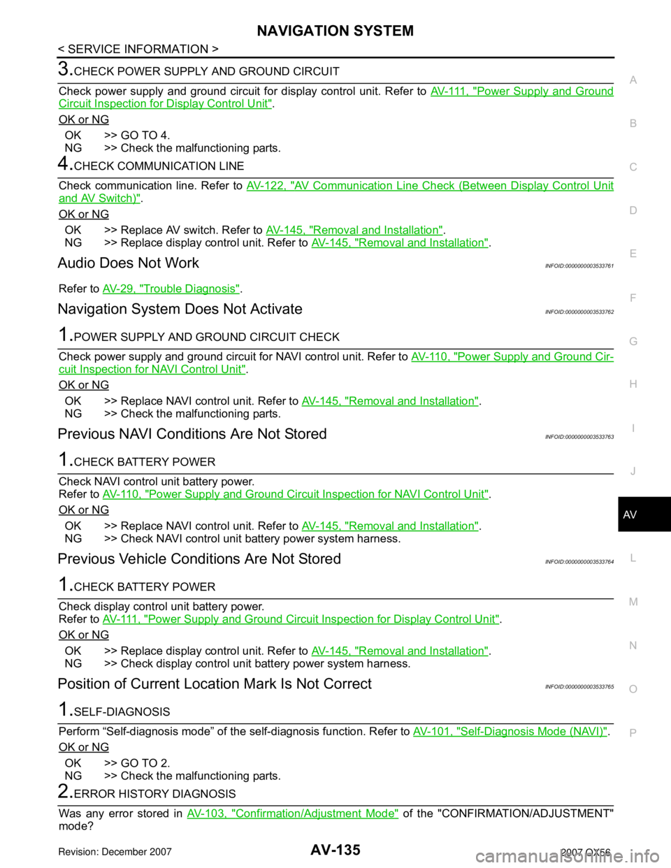
3.CHECK POWER SUPPLY AND GROUND CIRCUIT
Check power supply and ground circuit for display control unit. Refer to AV- 111 , "
Power Supply and Ground
Circuit Inspection for Display Control Unit".
OK or NG
OK >> GO TO 4.
NG >> Check the malfunctioning parts.
4.CHECK COMMUNICATION LINE
Check communication line. Refer to AV-122, "
AV Communication Line Check (Between Display Control Unit
and AV Switch)".
OK or NG
OK >> Replace AV switch. Refer to AV-145, "Removal and Installation".
NG >> Replace display control unit. Refer to AV-145, "
Removal and Installation".
Audio Does Not WorkINFOID:0000000003533761
Refer to AV-29, "Trouble Diagnosis".
Navigation System Does Not ActivateINFOID:0000000003533762
1.POWER SUPPLY AND GROUND CIRCUIT CHECK
Check power supply and ground circuit for NAVI control unit. Refer to AV-110, "
Power Supply and Ground Cir-
cuit Inspection for NAVI Control Unit".
OK or NG
OK >> Replace NAVI control unit. Refer to AV-145, "Removal and Installation".
NG >> Check the malfunctioning parts.
Previous NAVI Conditions Are Not StoredINFOID:0000000003533763
1.CHECK BATTERY POWER
Check NAVI control unit battery power.
Refer to AV-110, "
Power Supply and Ground Circuit Inspection for NAVI Control Unit".
OK or NG
OK >> Replace NAVI control unit. Refer to AV-145, "Removal and Installation".
NG >> Check NAVI control unit battery power system harness.
Previous Vehicle Conditions Are Not StoredINFOID:0000000003533764
1.CHECK BATTERY POWER
Check display control unit battery power.
Refer to AV- 111 , "
Power Supply and Ground Circuit Inspection for Display Control Unit".
OK or NG
OK >> Replace display control unit. Refer to AV-145, "Removal and Installation".
NG >> Check display control unit battery power system harness.
Position of Current Location Mark Is Not CorrectINFOID:0000000003533765
1.SELF-DIAGNOSIS
Perform “Self-diagnosis mode” of the self-diagnosis function. Refer to AV-101, "
Self-Diagnosis Mode (NAVI)".
OK or NG
OK >> GO TO 2.
NG >> Check the malfunctioning parts.
2.ERROR HISTORY DIAGNOSIS
Was any error stored in AV-103, "
Confirmation/Adjustment Mode" of the "CONFIRMATION/ADJUSTMENT"
mode?
Page 1016 of 3061

COMBINATION METERSDI-5
< SERVICE INFORMATION >
C
DE
F
G H
I
J
L
M A
B
DI
N
O P
COMBINATION METERS
Component Parts and Har ness Connector LocationINFOID:0000000003533479
System DescriptionINFOID:0000000003533480
UNIFIED METER CONTROL UNIT
• Speedometer, odometer, tachometer, fuel gauge, oil pressure gauge, voltage gauge, A/T oil temperature
gauge, and water temperature gauge are controlled by the unified meter control unit, which is built into the
combination meter.
• Warning indicators are controlled by signals drawn fr om the CAN communication system, BCM (body control
module), and components connected directly to the combination meter.
• Digital meter is adopted for odometer/trip meters*, as well as the A/T position indicator display. *The record of the odometer is kept ev en if the battery cable is disconnected.
• Odometer/trip meters and A/T indicator segments can be checked in diagnosis mode.
• Meters/gauges can be checked in diagnosis mode.
Illumination control
The unified meter control unit outputs the speedometer, odometer/trip meters, tachometer, oil pressure gauge,
voltage meter, A/T indicator, A/T temperature gauge, fuel and temperature gauge lighting when the ignition
switch is turned on. When the lighting switch is turned on, the illumination control switch can be used to adjust
the brightness of the combination meter illuminati on and the odometer/trip meters and meter illumination.
When the ignition switch is turned from the OFF to the ON position, the combination meter dial lighting will
remain off for 0.7 seconds. For additional combination meter illumination control information, refer to LT-120,
"System Description".
1. IPDM E/R E122 2. Combination meter M24 3. Fuel level sensor unit and fuel pump
C5 (view with inspection hole cover
removed)
4. ECM E16 (view with battery re- moved) 5. ABS actuator and electric unit (con-
trol unit) E125 6. Oil pressure switch F4
A. Oil pan (upper)
7. A/T assembly F9
WKIA5718E
Page 1066 of 3061

REAR SONAR SYSTEM
DI-55
< SERVICE INFORMATION >
C
D
E
F
G
H
I
J
L
MA
B
DI
N
O
P
Component InspectionINFOID:0000000003533534
SONAR BUZZER
1. Disconnect the sonar buzzer connector.
2. Check continuity between buzzer terminal (+) and terminal (-)
REAR SONAR SYSTEM OFF SWITCH
Disconnect the rear sonar system OFF switch connector M116.
Check continuity between the following terminals.
REAR SONAR SYSTEM OFF INDICATOR
Disconnect the rear sonar system OFF switch connector M116, and
apply battery voltage (approx. 12V) to switch terminal 5. Check the
rear sonar system OFF indicator operation when switch terminal 6 is
connected to battery ground.
Removal and InstallationINFOID:0000000003533535
REAR SONAR SENSORS
Refer to EI-14, "Removal and Installation" for rear sonar sensor removal and installation procedures.
SONAR CONTROL UNIT
Removal
1. Remove luggage side finisher LH. Refer to EI-39 to gain access to sonar control unit.
2. Disconnect electrical connector then remove sonar control unit. Refer to DI-46, "
Component Parts and
Harness Connector Location".
Installation
Installation is in the reverse order of removal.(+) - (-) : Continuity should exist
WKIA2024E
Rear sonar system OFF
switch Terminal to be inspected Continuity
Depressed
1 - 2Ye s
Released No
WKIA2025E
Terminal to be in-
spectedCondition Operation
Rear sonar sys-
tem OFF switch5 Approx. 12V Rear sonar
system OFF
indicator lights 6Ground
WKIA2026E
Page 1177 of 3061

EC-94
< SERVICE INFORMATION >
TROUBLE DIAGNOSIS
Engine Control Component Parts Location
INFOID:0000000003531621
1. ECM 2. Battery current sensor 3. Power steering pressure sensor
4. Ignition coil (with power transistor)
and spark plug (bank 2)5. Refrigerant pressure sensor 6. Intake valve timing control position
sensor (bank 2)
7. Intake valve timing control solenoid
valve (bank 2)8. Engine coolant temperature sensor 9. Electric throttle control actuator
10. Intake valve timing control position
sensor (bank 1)11. Intake valve timing control solenoid
valve (bank 1)12. Cooling fan motor
13. Camshaft position sensor (PHASE) 14. Ignition coil (with power transistor)
and spark plug (bank 1)15. Mass air flow sensor (with intake air
temperature sensor)
16. A/F sensor 1 (bank 1) 17. EVAP service port 18. Fuel injector (bank 1)
19. Knock sensor (bank 1) 20. EVAP canister purge volume control
solenoid valve21. Knock sensor (bank 2)
22. Fuel injector (bank 2) 23. A/F sensor 1 (bank 2) 24. IPDM E/R
BBIA0743E
Page 1234 of 3061

DTC P0011, P0021 IVT CONTROL
EC-151
< SERVICE INFORMATION >
C
D
E
F
G
H
I
J
K
L
MA
EC
N
P O
• If DTC Confirmation Procedure has been previously conducted, always turn ignition switch OFF and wait at
least 10 seconds before conducting the next test.
TESTING CONDITION:
Before performing the following procedure, confirm that battery voltage is between 10V and 16V at
idle.
PROCEDURE FOR MALFUNCTION A
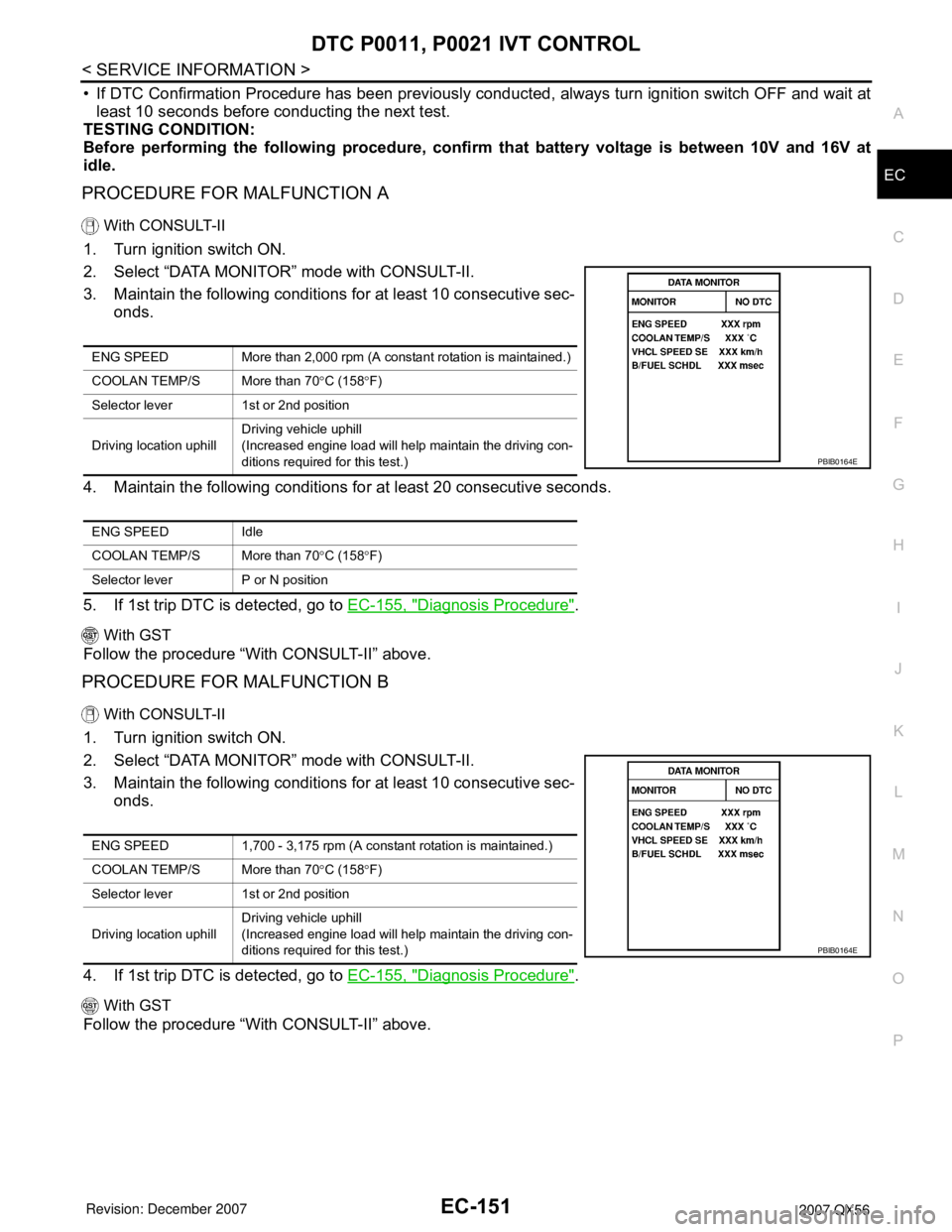
With CONSULT-II
1. Turn ignition switch ON.
2. Select “DATA MONITOR” mode with CONSULT-II.
3. Maintain the following conditions for at least 10 consecutive sec-
onds.
4. Maintain the following conditions for at least 20 consecutive seconds.
5. If 1st trip DTC is detected, go to EC-155, "
Diagnosis Procedure".
With GST
Follow the procedure “With CONSULT-II” above.
PROCEDURE FOR MALFUNCTION B
With CONSULT-II
1. Turn ignition switch ON.
2. Select “DATA MONITOR” mode with CONSULT-II.
3. Maintain the following conditions for at least 10 consecutive sec-
onds.
4. If 1st trip DTC is detected, go to EC-155, "
Diagnosis Procedure".
With GST
Follow the procedure “With CONSULT-II” above.
ENG SPEED More than 2,000 rpm (A constant rotation is maintained.)
COOLAN TEMP/S More than 70°C (158°F)
Selector lever 1st or 2nd position
Driving location uphillDriving vehicle uphill
(Increased engine load will help maintain the driving con-
ditions required for this test.)
ENG SPEED Idle
COOLAN TEMP/S More than 70°C (158°F)
Selector lever P or N position
PBIB0164E
ENG SPEED 1,700 - 3,175 rpm (A constant rotation is maintained.)
COOLAN TEMP/S More than 70°C (158°F)
Selector lever 1st or 2nd position
Driving location uphillDriving vehicle uphill
(Increased engine load will help maintain the driving con-
ditions required for this test.)
PBIB0164E
Page 1969 of 3061

PRECAUTIONS
GI-3
< SERVICE INFORMATION >
C
D
E
F
G
H
I
J
K
L
MB
GI
N
O
P
General PrecautionINFOID:0000000003531471
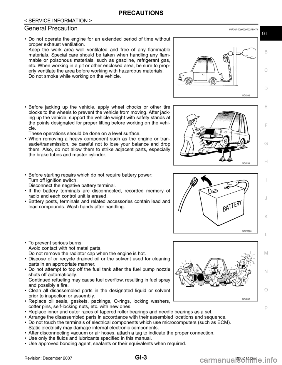
• Do not operate the engine for an extended period of time without
proper exhaust ventilation.
Keep the work area well ventilated and free of any flammable
materials. Special care should be taken when handling any flam-
mable or poisonous materials, such as gasoline, refrigerant gas,
etc. When working in a pit or other enclosed area, be sure to prop-
erly ventilate the area before working with hazardous materials.
Do not smoke while working on the vehicle.
• Before jacking up the vehicle, apply wheel chocks or other tire
blocks to the wheels to prevent the vehicle from moving. After jack-
ing up the vehicle, support the vehicle weight with safety stands at
the points designated for proper lifting before working on the vehi-
cle.
These operations should be done on a level surface.
• When removing a heavy component such as the engine or tran-
saxle/transmission, be careful not to lose your balance and drop
them. Also, do not allow them to strike adjacent parts, especially
the brake tubes and master cylinder.
• Before starting repairs which do not require battery power:
Turn off ignition switch.
Disconnect the negative battery terminal.
• If the battery terminals are disconnected, recorded memory of
radio and each control unit is erased.
• Battery posts, terminals and related accessories contain lead and
lead compounds. Wash hands after handling.
• To prevent serious burns:
Avoid contact with hot metal parts.
Do not remove the radiator cap when the engine is hot.
• Dispose of or recycle drained oil or the solvent used for cleaning
parts in an appropriate manner.
• Do not attempt to top off the fuel tank after the fuel pump nozzle
shuts off automatically.
Continued refueling may cause fuel overflow, resulting in fuel spray
and possibly a fire.
• Clean all disassembled parts in the designated liquid or solvent
prior to inspection or assembly.
• Replace oil seals, gaskets, packings, O-rings, locking washers,
cotter pins, self-locking nuts, etc. with new ones.
• Replace inner and outer races of tapered roller bearings and needle bearings as a set.
• Arrange the disassembled parts in accordance with their assembled locations and sequence.
• Do not touch the terminals of electrical components which use microcomputers (such as ECM).
Static electricity may damage internal electronic components.
• After disconnecting vacuum or air hoses, attach a tag to indicate the proper connection.
• Use only the fluids and lubricants specified in this manual.
• Use approved bonding agent, sealants or their equivalents when required.
SGI285
SGI231
SEF289H
SGI233
Page 1975 of 3061

HOW TO USE THIS MANUAL
GI-9
< SERVICE INFORMATION >
C
D
E
F
G
H
I
J
K
L
MB
GI
N
O
P
SYMBOLS
How to Follow Trouble DiagnosisINFOID:0000000003531484
DESCRIPTION
NOTICE:
Trouble diagnoses indicate work procedures required to diagnose problems effectively. Observe the following
instructions before diagnosing.
1.Before performing trouble diagnoses, read the “Preliminary Check”, the “Symptom Chart” or the
“Work Flow”.
2.After repairs, re-check that the problem has been completely eliminated.
3.Refer to Component Parts and Harness Connector Location for the Systems described in each
section for identification/location of components and harness connectors.
4.Refer to the Circuit Diagram for quick pinpoint check.
If you need to check circuit continuity between harness connectors in more detail, such as when a
sub-harness is used, refer to Wiring Diagram in each individual section and Harness Layout in PG
section for identification of harness connectors.
5.When checking circuit continuity, ignition switch should be OFF.
6.Before checking voltage at connectors, check battery voltage.
7.After accomplishing the Diagnostic Procedures and Electrical Components Inspection, make sure
that all harness connectors are reconnected as they were.
SAIA0749E
Page 1982 of 3061

GI-16
< SERVICE INFORMATION >
HOW TO USE THIS MANUAL
Optional Splice
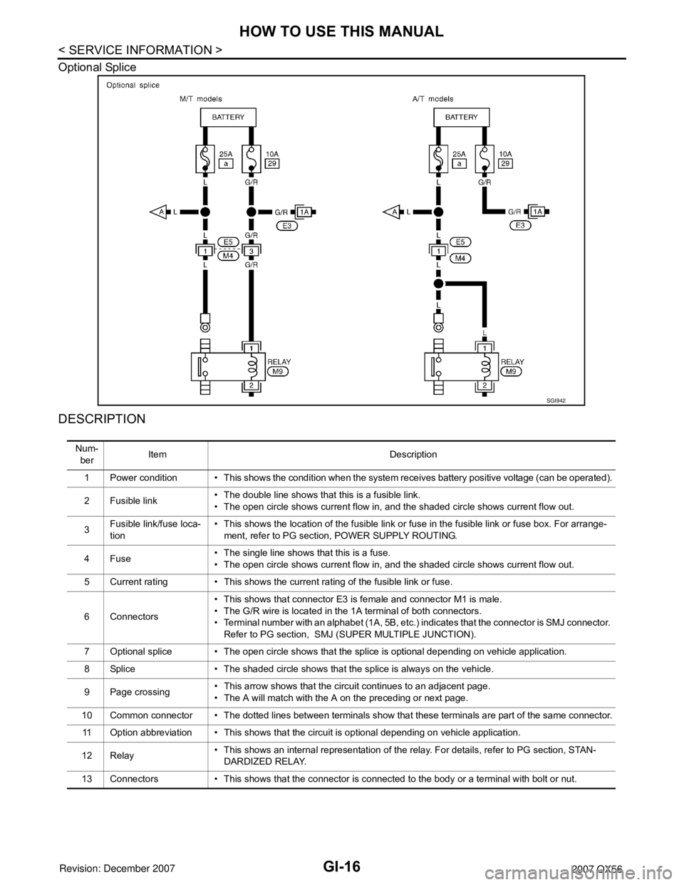
DESCRIPTION
SGI942
Num-
berItem Description
1 Power condition • This shows the condition when the system receives battery positive voltage (can be operated).
2 Fusible link• The double line shows that this is a fusible link.
• The open circle shows current flow in, and the shaded circle shows current flow out.
3Fusible link/fuse loca-
tion• This shows the location of the fusible link or fuse in the fusible link or fuse box. For arrange-
ment, refer to PG section, POWER SUPPLY ROUTING.
4Fuse• The single line shows that this is a fuse.
• The open circle shows current flow in, and the shaded circle shows current flow out.
5 Current rating • This shows the current rating of the fusible link or fuse.
6 Connectors• This shows that connector E3 is female and connector M1 is male.
• The G/R wire is located in the 1A terminal of both connectors.
• Terminal number with an alphabet (1A, 5B, etc.) indicates that the connector is SMJ connector.
Refer to PG section, SMJ (SUPER MULTIPLE JUNCTION).
7 Optional splice • The open circle shows that the splice is optional depending on vehicle application.
8 Splice • The shaded circle shows that the splice is always on the vehicle.
9 Page crossing• This arrow shows that the circuit continues to an adjacent page.
• The A will match with the A on the preceding or next page.
10 Common connector • The dotted lines between terminals show that these terminals are part of the same connector.
11 Option abbreviation • This shows that the circuit is optional depending on vehicle application.
12 Relay• This shows an internal representation of the relay. For details, refer to PG section, STAN-
DARDIZED RELAY.
13 Connectors • This shows that the connector is connected to the body or a terminal with bolt or nut.
Page 2301 of 3061

LT-94
< SERVICE INFORMATION >
TRAILER TOW
TRAILER TOW
Component Parts and Harness Connector LocationINFOID:0000000003533451
System DescriptionINFOID:0000000003533452
Power is supplied at all times
• to ignition relay, located in the IPDM E/R (intelligent power distribution module engine room),
• through 50A fusible link (letter f , located in the fuse and fusible link box)
• to BCM (body control module) terminal 70,
• through 10A fuse (No. 32, located in the IPDM E/R)
• through IPDM E/R terminal 61
1. Fuse and fusible link box 2. IPDM E/R fuse layout 3. Fuse and relay box
4. IPDM E/R E118, E119, E120, E121,
E122, E123, E1245. A. Steering column
B. Data link connector M22
C. BCM M18, M19, M20
(view with instrument lower panel LH
removed)6. A. Trailer turn relay LH E156
B. Battery
C. Trailer tow relay 2 E140
D. Trailer turn relay RH E157
7. A. Trailer tow relay 1 M51
B. Electric brake (pre-wiring) M76
(view with instrument lower panel LH
removed)8. Trailer connector C2 9. Combination switch (lighting switch)
M28
WKIA4616E