Engine Lubrication INFINITI QX56 2007 Factory Service Manual
[x] Cancel search | Manufacturer: INFINITI, Model Year: 2007, Model line: QX56, Model: INFINITI QX56 2007Pages: 3061, PDF Size: 64.56 MB
Page 1 of 3061

-1
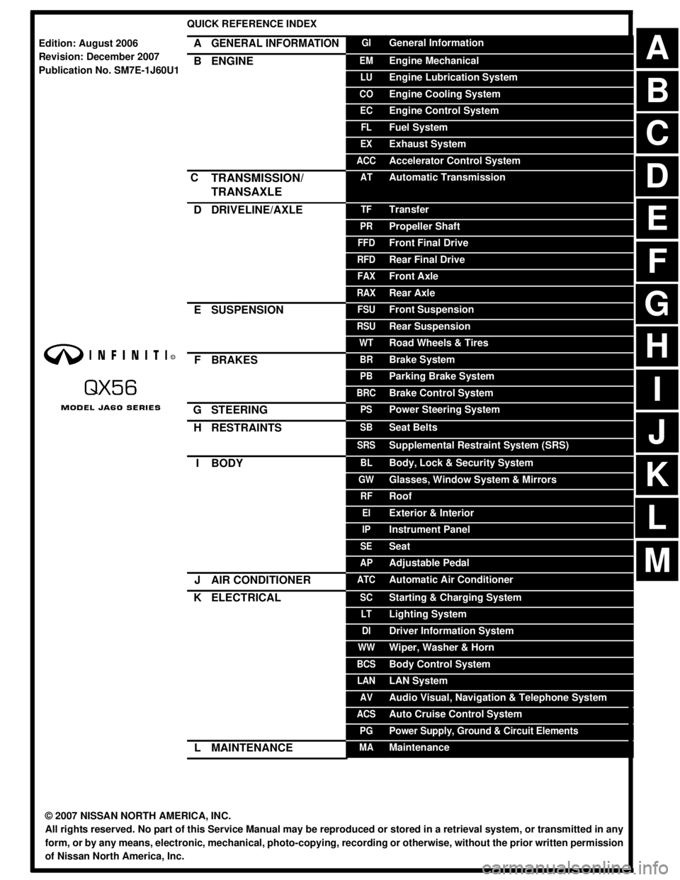
QUICK REFERENCE INDEX
AGENERAL INFORMATIONGIGeneral Information
BENGINEEMEngine Mechanical
LUEngine Lubrication System
COEngine Cooling System
ECEngine Control System
FLFuel System
EXExhaust System
ACCAccelerator Control System
CTRANSMISSION/
TRANSAXLEATAutomatic Transmission
DDRIVELINE/AXLETFTransfer
PRPropeller Shaft
FFDFront Final Drive
RFDRear Final Drive
FAXFront Axle
RAXRear Axle
ESUSPENSIONFSUFront Suspension
RSURear Suspension
WTRoad Wheels & Tires
FBRAKESBRBrake System
PBParking Brake System
BRCBrake Control System
GSTEERINGPSPower Steering System
HRESTRAINTSSBSeat Belts
SRSSupplemental Restraint System (SRS)
IBODYBLBody, Lock & Security System
GWGlasses, Window System & Mirrors
RFRoof
EIExterior & Interior
IPInstrument Panel
SESeat
APAdjustable Pedal
JAIR CONDITIONERATCAutomatic Air Conditioner
KELECTRICALSCStarting & Charging System
LTLighting System
DIDriver Information System
WWWiper, Washer & Horn
BCSBody Control System
LANLAN System
AVAudio Visual, Navigation & Telephone System
ACSAuto Cruise Control System
PGPower Supply, Ground & Circuit Elements
LMAINTENANCEMAMaintenance
Edition: August 2006
Revision: December 2007
Publication No. SM7E-1J60U1
B
D
© 2007 NISSAN NORTH AMERICA, INC.
All rights reserved. No part of this Service Manual may be reproduced or stored in a retrieval system, or transmitted in any
form, or by any means, electronic, mechanical, photo-copying, recording or otherwise, without the prior written permission
of Nissan North America, Inc.
A
C
E
F
G
H
I
J
K
L
M
Page 108 of 3061

AT-38
< SERVICE INFORMATION >
A/T CONTROL SYSTEM
FUNCTION OF PRESSURE SWITCH
Pilot valve AAdjusts the line pressure and produces the constant pressure (pilot pressure) required
for line pressure control, shift change control, and lock-up control.
Pilot valve BAdjusts the line pressure and produces the constant pressure (pilot pressure) required
for shift change control.
Low coast brake switching valve During engine braking, supplies the line pressure to the low coast brake reducing valve.
Low coast brake reducing valveWhen the low coast brake is coupled, adjusts the line pressure to the optimum pressure
(low coast brake pressure) and supplies it to the low coast brake.
N-R accumulator Produces the stabilizing pressure for when N-R is selected.
Direct clutch piston switching valve Operates in 4th gear and switches the direct clutch coupling capacity.
High and low reverse clutch control valveWhen the high and low reverse clutch is coupled, adjusts the line pressure to the opti-
mum pressure (high and low reverse clutch pressure) and supplies it to the high and low
reverse clutch. (In 1st, 3rd, 4th and 5th gears, adjusts the clutch pressure.)
Input clutch control valveWhen the input clutch is coupled, adjusts the line pressure to the optimum pressure (in-
put clutch pressure) and supplies it to the input clutch. (In 4th and 5th gears, adjusts the
clutch pressure.)
Direct clutch control valveWhen the direct clutch is coupled, adjusts the line pressure to the optimum pressure (di-
rect clutch pressure) and supplies it to the direct clutch. (In 2nd, 3rd, and 4th gears, ad-
justs the clutch pressure.)
TCC control valve
TCC control plug
TCC control sleeveSwitches the lock-up to operating or released. Also, by performing the lock-up operation
transiently, lock-up smoothly.
Torque converter lubrication valveOperates during lock-up to switch the torque converter, cooling, and lubrication system
oil path.
Cool bypass valve Allows excess oil to bypass cooler circuit without being fed into it.
Line pressure relief valve Discharges excess oil from line pressure circuit.
N-D accumulator Produces the stabilizing pressure for when N-D is selected.
Manual valveSends line pressure to each circuit according to the select position. The circuits to which
the line pressure is not sent drain. Name Function
Name Function
Pressure switch 1 (FR/B)Detects any malfunction in the front brake hydraulic pressure. When it detects any mal-
function, it puts the system into fail-safe mode.
Pressure switch 2 (LC/B)Detects any malfunction in the low coast brake hydraulic pressure. When it detects any
malfunction, it puts the system into fail-safe mode.
Pressure switch 3 (I/C)Detects any malfunction in the input clutch hydraulic pressure. When it detects any mal-
function, it puts the system into fail-safe mode.
Pressure switch 5 (D/C)Detects any malfunction in the direct clutch hydraulic pressure. When it detects any mal-
function, it puts the system into fail-safe mode.
Pressure switch 6 (HLR/C)Detects any malfunction in the high and low reverse clutch hydraulic pressure. When it
detects any malfunction, it puts the system into fail-safe mode.
Page 1948 of 3061

FSU-2
< SERVICE INFORMATION >
PRECAUTIONS
SERVICE INFORMATION
PRECAUTIONS
PrecautionINFOID:0000000003532631
• When installing the rubber bushings, the final tightening must be done under unladen condition and with the
tires on level ground. Oil will shorten the life of the rubber bushings, so wipe off any spilled oil immediately.
• Unladen condition means the fuel tank, engine coolant and lubricants are at the full specification. The spare
tire, jack, hand tools, and mats are in their designated positions.
• After installing suspension components, check the wheel alignment.
• Lock nuts are not reusable. Always use new lock nuts for installation. New lock nuts are pre-oiled, do not
apply any additional lubrication.
Page 2110 of 3061

IDX-6
ALPHABETICAL INDEX
Line pressure solenoid valve ........................... AT-118
Line pressure switch (Transfer) .......... TF-154, TF-167
Line pressure test (A/T) ..................................... AT-52
Location of electrical units ................................. PG-65
Low coast brake solenoid valve ......... AT-151, AT-153
Low tire pressure warning system ...................... WT-8
Low tire pressure warning system - trouble diagnoses .
WT-11
Low tire pressure warning system - Wiring diagram .....
WT-11
Lubricant (R134a) A/C ..................................... ATC-22
Lubricants ......................................................... MA-11
Lubrication circuit (engine) ................................... LU-6
Lubrication oil A/C ............................................ ATC-22
Lubrication-locks, hinges and hood latches ...... MA-31
M
MAFS - Wiring diagram ..................... EC-200
, EC-208
Magnet clutch ............................... ATC-115, ATC-180
MAIN - Wiring diagram ...................... EC-150, AT-163
Main oil pump (Transfer) ..................... TF-154, TF-167
Mainshaft (Transfer) ........................... TF-154, TF-167
Maintenance (engine)Schedule 1 ....................... MA-7
Maintenance (engine)Schedule 2 ....................... MA-9
Major overhaul (Final drive) ............................. FFD-14
Major overhaul (Transfer) ................................ TF-146
Malfunction indicator lamp (MIL) ........................ EC-65
Map lamp .......................................................... LT-111
Mass air flow sensor (MAFS) ............. EC-197, EC-206
Meter ..................................................................... DI-5
METER - Wiring diagram ...................................... DI-9
MIL data link connectors circuit ....................... EC-697
MIL/DL - Wiring diagram .................................. EC-697
MIRROR - Wiring diagram ................................ GW-87
Misfire .............................................................. EC-350
Mode door control linkage adjustment ............. ATC-65
Mode door motor ............................ ATC-62, ATC-165
Model variation ................................................... GI-48
Multiport fuel injection (MFI) system .................. EC-25
Multiport fuel injection precautions ....................... GI-6
Multi-remote control system - See Remote keyless entry
system ............................................................... BL-40
N
NATS - Wiring diagram .................................... BL-130
NAVI - Wiring diagram ....................................... AV-86
NAVI Control Unit .............................................. AV-83
Navigation system ............................................. AV-81
Neutral-4LO switch ............................................ TF-61
NONDTC - Wiring diagram .............................. AT-172
NVH troubleshooting (AX) ................................. FAX-4
NVH troubleshooting (EM) ................................ EM-10
NVH troubleshooting (Final drive) ..................... RFD-7
NVH troubleshooting (Propeller shaft) ................. PR-3
NVH troubleshooting (RAX) .............................. RAX-4
NVH troubleshooting (RSU) .............................. RSU-5
NVH troubleshooting (ST) .................................... PS-5
NVH troubleshooting (Transfer) ......................... TF-10
NVH troubleshooting (WT)NVH troubleshooting (WT) ..
WT-4
NVIS (Nissan vehicle immobilizer system) precautions
GI-3
O
O2H2B1 - Wiring diagram ............................... EC-183
O2H2B2 - Wiring diagram ............................... EC-185
O2S2B1 - Wiring diagram ... EC-279, EC-290, EC-303
O2S2B2 - Wiring diagram ... EC-281, EC-292, EC-305
Oil cooler (engine) .............................................. LU-12
Oil filter ............................................................... LU-11
Oil filter (Transfer) ............................................ TF-143
Oil pan (engine) ................................................ EM-24
Oil pressure (engine) ........................................... LU-8
Oil pressure relief valve (engine) ......................... LU-6
Oil pump (engine) .............................................. LU-14
Oil seal replacement (engine) ........................... EM-60
Oil seal replacement (front of final drive) FFD-8, RFD-9
Oil seal replacement (side of final drive) ......... RFD-11
On board diagnostic system ............................. EC-49
ORVR (On-board Refueling Vapor Recovery) .. EC-40
Overheat ......................................................... EC-504
P
P/SCKT - Wiring diagram ................................. WW-46
Pantograph jack .................................................. GI-42
Park/Neutral position switch ............................ EC-487
Parking brake control ........................................... PB-4
PCV (positive crankcase ventilation) ................ EC-46
Periodic maintenance ......................................... MA-7
Personal lamp .................................................. LT-111
PGC/V - Wiring diagram ................... EC-397, EC-405
PHASE - Wiring diagram ................................ EC-371
PHONE - Wiring diagram ................................... AV-65
Pinion bearing preload diff. ............................. RFD-26
Piston pin inspection ......................................... EM-94
Piston ring inspection ........................................ EM-95
Piston to bore clearance ................................... EM-99
Planetary carrier (Transfer) ................. TF-149, TF-176
PNP/SW - Wiring diagram ... EC-489, AT-101, AT-102
POS - Wiring diagram ..................................... EC-364
POWER - Wiring diagram ................................... PG-6
Power door lock ................................................. BL-16
Power seat ......................................................... SE-81
Power steering fluid level .................................. MA-29
Power steering gear ........................................... PS-15
Power steering oil pump .................................... PS-22
Power steering pressure (PSP) sensor ........... EC-470
Power steering system bleeding .......................... PS-6
Power supply routing .......................................... PG-4
Power window .................................................. GW-15
PRE/SE - Wiring diagram ................. EC-429, EC-435
Precautions (General) ........................................... GI-4
Precautions in repairing high strength steel ..... BL-182
Pressure switch 1 ............................... AT-141, AT-155
Page 2346 of 3061

LU-1
ENGINE
C
D
E
F
G
H
I
J
K
L
M
SECTION LU
A
LU
N
O
P
CONTENTS
ENGINE LUBRICATION SYSTEM
SERVICE INFORMATION ............................2
PRECAUTIONS ...................................................2
Precaution for Supplemental Restraint System
(SRS) "AIR BAG" and "SEAT BELT PRE-TEN-
SIONER" ...................................................................
2
Precaution for Liquid Gasket .....................................2
PREPARATION ...................................................4
Special Service Tool .................................................4
Commercial Service Tool ..........................................4
LUBRICATION SYSTEM ....................................6
Lubrication Circuit .....................................................6
Schematic .................................................................7
ENGINE OIL ........................................................8
Inspection .................................................................8
Changing Engine Oil .................................................9
OIL FILTER .......................................................11
Removal and Installation .........................................11
OIL COOLER ....................................................12
Removal and Installation .........................................12
OIL PUMP .........................................................14
Removal and Installation .........................................14
Disassembly and Assembly .....................................15
SERVICE DATA AND SPECIFICATIONS
(SDS) .................................................................
17
Standard and Limit ..................................................17
Page 2592 of 3061

RSU-2
< SERVICE INFORMATION >
PRECAUTIONS
SERVICE INFORMATION
PRECAUTIONS
Precaution for Supplemental Restraint System (SRS) "AIR BAG" and "SEAT BELT
PRE-TENSIONER"
INFOID:0000000003532652
The Supplemental Restraint System such as “AIR BAG” and “SEAT BELT PRE-TENSIONER”, used along
with a front seat belt, helps to reduce the risk or severity of injury to the driver and front passenger for certain
types of collision. This system includes seat belt switch inputs and dual stage front air bag modules. The SRS
system uses the seat belt switches to determine the front air bag deployment, and may only deploy one front
air bag, depending on the severity of a collision and whether the front occupants are belted or unbelted.
Information necessary to service the system safely is included in the SRS and SB section of this Service Man-
ual.
WARNING:
• To avoid rendering the SRS inoperative, which could increase the risk of personal injury or death in
the event of a collision which would result in air bag inflation, all maintenance must be performed by
an authorized NISSAN/INFINITI dealer.
• Improper maintenance, including incorrect removal and installation of the SRS, can lead to personal
injury caused by unintentional activation of the system. For removal of Spiral Cable and Air Bag
Module, see the SRS section.
• Do not use electrical test equipment on any circuit related to the SRS unless instructed to in this
Service Manual. SRS wiring harnesses can be identified by yellow and/or orange harnesses or har-
ness connectors.
Precaution for Rear SuspensionINFOID:0000000003532653
• When installing the rubber bushings, the final tightening must be done under unladen condition and with the
tires on level ground. Oil will shorten the life of the rubber bushings, so wipe off any spilled oil immediately.
• Unladen condition means the fuel tank, engine coolant and lubricants are at the full specification. The spare
tire, jack, hand tools, and mats are in their designated positions.
• After installing suspension components, check the wheel alignment.
• Caulking nuts are not reusable. Always use new caulking nuts for installation. New caulking nuts are pre-
oiled, do not apply any additional lubrication.