door lock INFINITI QX56 2007 Factory User Guide
[x] Cancel search | Manufacturer: INFINITI, Model Year: 2007, Model line: QX56, Model: INFINITI QX56 2007Pages: 3061, PDF Size: 64.56 MB
Page 693 of 3061
BCS-6
< SERVICE INFORMATION >
BCM (BODY CONTROL MODULE)
• When CAN communication operation is detected, it switches to CAN communication status.
• When a state of the following switches changes, it switches to CAN communication state:
- Ignition switch
- Key switch (insert)
- Hazard switch
- Main door lock/unlock switch
- Front door switch (LH, RH)
- Rear door switch (LH, RH)
- Back latch (door ajar switch)
- Glass hatch ajar switch
- Combination switch (passing, lighting switch 1st position, front fog lamp)
- Keyfob (lock/unlock signal)
- Front door lock assembly LH (key cylinder switch)
• When control performed only by BCM is required by switch, it shifts to CAN communication inactive
mode.
• Status of combination switch reading function is changed.
SYSTEMS CONTROLLED BY BCM DIRECTLY
• Power door lock system. Refer to BL-15.
• Remote keyless entry system. Refer to BL-37
.
• Power window system. Refer to GW-15
. NOTE
• Sunroof system. Refer to RF-10. NOTE
• Room lamp timer. Refer to LT-101.
• Warning chime system. Refer to DI-36
.
• Turn signal and hazard warning lamps system. Refer to LT- 5 7
.
• Trailer turn signal and hazard warning lamps system (if equipped). Refer to LT- 9 4
.
• Rear wiper and washer system. Refer to WW-26
.
NOTE:
Power supply only. No system control.
SYSTEMS CONTROLLED BY BCM AND IPDM E/R
• Panic system. Refer to BL-37.
• Vehicle security system. Refer to BL-60
.
• IVIS (NATS) system. Refer to BL-116
.
• Headlamp, tail lamp, front fog lamp, auto light and battery saver control systems. Refer to LT- 5
, LT- 2 4, LT- 8 2,
LT- 4 9
or LT- 3 4.
• Front wiper and washer system. Refer to WW-3
.
• Rear window defogger system. Refer to GW-68
.
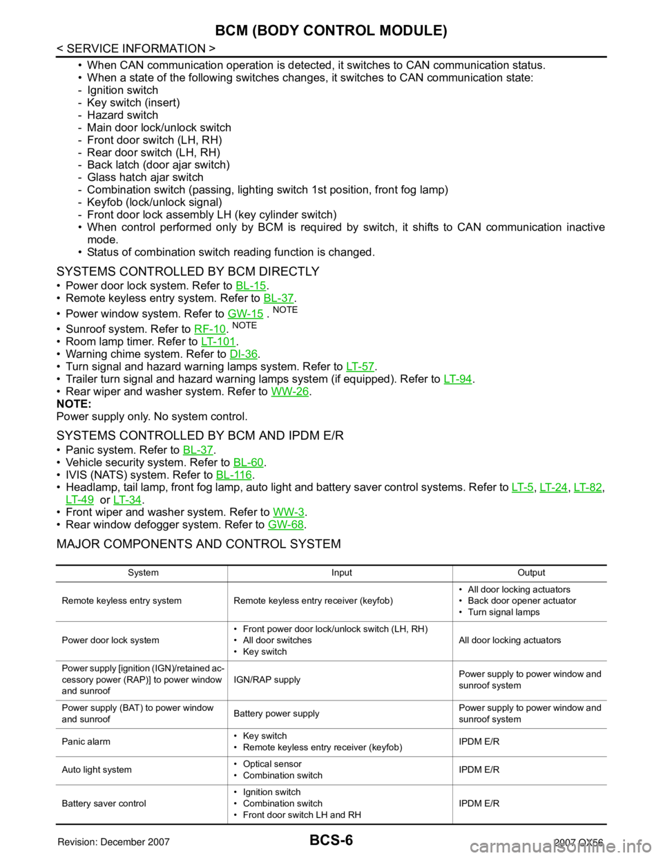
MAJOR COMPONENTS AND CONTROL SYSTEM
System Input Output
Remote keyless entry system Remote keyless entry receiver (keyfob)• All door locking actuators
• Back door opener actuator
• Turn signal lamps
Power door lock system• Front power door lock/unlock switch (LH, RH)
• All door switches
• Key switchAll door locking actuators
Power supply [ignition (IGN)/retained ac-
cessory power (RAP)] to power window
and sunroofIGN/RAP supplyPower supply to power window and
sunroof system
Power supply (BAT) to power window
and sunroofBattery power supplyPower supply to power window and
sunroof system
Panic alarm• Key switch
• Remote keyless entry receiver (keyfob)IPDM E/R
Auto light system• Optical sensor
• Combination switchIPDM E/R
Battery saver control• Ignition switch
• Combination switch
• Front door switch LH and RHIPDM E/R
Page 694 of 3061

BCM (BODY CONTROL MODULE)
BCS-7
< SERVICE INFORMATION >
C
D
E
F
G
H
I
J
L
MA
B
BCS
N
O
P
CAN Communication System DescriptionINFOID:0000000003533597
Refer to LAN-4.
Headlamp Combination switch IPDM E/R
Tail lamp Combination switch IPDM E/R
Front fog lamp Combination switch IPDM E/R
Turn signal lamp Combination switch• Turn signal lamp
• Combination meter
Hazard lamp Hazard switch• Turn signal lamp
• Combination meter
Room lamp timer• Key switch
• Remote keyless entry receiver (keyfob)
• Main power window and door lock/unlock switch
• Front door lock assembly LH (key cylinder switch)
• All door switchesInterior room lamp
Key warning chime• Key switch
• Front door switch LHCombination meter (warning buzz-
er)
Light warning chime• Combination switch
• Key switch
• Front door switch LHCombination meter (warning buzz-
er)
Vehicle-speed-sensing intermittent wip-
er• Combination switch
• Combination meterIPDM E/R
Rear window defogger Rear window defogger switch IPDM E/R
Air conditioner switch signal Front air control ECM
Blower fan switch signal Front air control ECM
Low tire pressure warning system Remote keyless entry receiver• Combination meter
• Display control unit
Trailer tow (if equipped) Combination switch Trailer turn signal relays
Vehicle security system• Remote keyless entry receiver (keyfob)
• Main power window and door lock/unlock switch
• Power window and door lock/unlock switch RH
• Front door lock assembly LH (key cylinder switch)
• All door switches
• Back door latch (door ajar switch)• IPDM E/R
• Security indicator lamp System Input Output
Page 698 of 3061

BCM (BODY CONTROL MODULE)
BCS-11
< SERVICE INFORMATION >
C
D
E
F
G
H
I
J
L
MA
B
BCS
N
O
P
Terminal and Reference Value for BCMINFOID:0000000003533600
Te r m i n a lWire
colorSignal nameSignal
input/
outputMeasuring condition
Reference value or waveform
(Approx.) Ignition
switchOperation or condition
1BR/WIgnition keyhole illumi-
nationOutput OFFDoor is locked (SW OFF) Battery voltage
Door is unlocked (SW ON) 0V
2SBCombination switch
input 5Input ONLighting, turn, wiper OFF
Wiper dial position 4
3G/YCombination switch
input 4Input ONLighting, turn, wiper OFF
Wiper dial position 4
4YCombination switch
input 3Input ONLighting, turn, wiper OFF
Wiper dial position 4
5G/BCombination switch
input 2
Input ONLighting, turn, wiper OFF
Wiper dial position 4
6VCombination switch
input 1
9Y/BRear window defogger
switchInput ONRear window defogger switch
ON0V
Rear window defogger switch
OFF5V
10 G Hazard lamp flash Input OFFON (opening or closing) 0V
OFF (other than above) Battery voltage
11 OIgnition switch (ACC
or ON)InputACC or
ONIgnition switch ACC or ON Battery voltage
12 R/L Front door switch RH Input OFFON (open) 0V
OFF (closed) Battery voltage
13 GR Rear door switch RH Input OFFON (open) 0V
OFF (closed) Battery voltage
15 L/WTire pressure warning
check connectorInput OFF — 5V
SKIA5291E
SKIA5292E
SKIA5291E
SKIA5292E
Page 700 of 3061

BCM (BODY CONTROL MODULE)
BCS-13
< SERVICE INFORMATION >
C
D
E
F
G
H
I
J
L
MA
B
BCS
N
O
P
27 W/RCompressor ON sig-
nalInput ONA/C switch OFF 5V
A/C switch ON 0V
28 L/R Front blower monitor Input ONFront blower motor OFF Battery voltage
Front blower motor ON 0V
29 W/B Hazard switch Input OFFON 0V
OFF 5V
30 Y/BR Glass hatch switch Input OFFGlass hatch switch released
→ Glass hatch switch pressedBattery voltage → 0V
32 R/GCombination switch
output 5Output ONLighting, turn, wiper OFF
Wiper dial position 4
33 R/YCombination switch
output 4Output ONLighting, turn, wiper OFF
Wiper dial position 4
34 LCombination switch
output 3Output ONLighting, turn, wiper OFF
Wiper dial position 4
35 O/BCombination switch
output 2
Output ONLighting, turn, wiper OFF
Wiper dial position 4
36 R/WCombination switch
output 1
37 B/RKey switch and key
lock solenoidInput OFFKey inserted Battery voltage
Key removed 0V
38 W/L Ignition switch (ON) Input ON — Battery voltage
39 L CAN-H — — — —
40 P CAN-L — — — —
42 GRGlass hatch ajar
switchInput ONGlass hatch open 0
Glass hatch closed Battery
43 R/BBack door latch (door
ajar switch)Input OFFON (open) 0V
OFF (closed) Battery voltage Te r m i n a lWire
colorSignal nameSignal
input/
outputMeasuring condition
Reference value or waveform
(Approx.) Ignition
switchOperation or condition
SKIA5291E
SKIA5292E
SKIA5291E
SKIA5292E
Page 701 of 3061

BCS-14
< SERVICE INFORMATION >
BCM (BODY CONTROL MODULE)
44 ORear wiper auto stop
switch 1Input ONRise up position (rear wiper
arm on stopper)0V
A Position (full clockwise stop
position)Battery voltage
Forward sweep (counterclock-
wise direction)Fluctuating
B Position (full counterclock-
wise stop position)0V
Reverse sweep (clockwise di-
rection)Fluctuating
47 SB Front door switch LH Input OFFON (open) 0V
OFF (closed) Battery voltage
48 R/Y Rear door switch LH Input OFFON (open) 0V
OFF (closed) Battery voltage
49 R Cargo lamp Output OFFAny door open (ON) 0V
All doors closed (OFF) Battery voltage
51 Y/BTrailer turn signal
(right)Output ON Turn right ON
52 G/B Trailer turn signal (left) Output ON Turn left ON
53 L/WGlass hatch lock actu-
atorInput OFFGlass hatch switch released
→ Glass hatch switch pressed0V → Battery voltage for 300
msec.
54 YRear wiper output cir-
cuit 2Input ONRise up position (rear wiper
arm on stopper)0V
A Position (full clockwise stop
position)0V
Forward sweep (counterclock-
wise direction)0V
B Position (full counterclock-
wise stop position)Battery voltage
Reverse sweep (clockwise di-
rection)Battery voltage
55 SBRear wiper output cir-
cuit 1Output ONOFF 0
ON Battery voltage
56 R/G Battery saver output OutputOFF30 minutes after ignition
switch is turned OFF0V
ON — Battery voltage
57 Y/R Battery power supply Input OFF — Battery voltage Te r m i n a lWire
colorSignal nameSignal
input/
outputMeasuring condition
Reference value or waveform
(Approx.) Ignition
switchOperation or condition
SKIA3009J
SKIA3009J
Page 702 of 3061

BCM (BODY CONTROL MODULE)
BCS-15
< SERVICE INFORMATION >
C
D
E
F
G
H
I
J
L
MA
B
BCS
N
O
P
BCM Power Supply and Ground Circuit InspectionINFOID:0000000003533601
1.CHECK FUSES AND FUSIBLE LINK
• Check 50A fusible link (letter f, located in the fuse and fusible link box).
• Check 10A fuse [No. 4, located in the fuse block (J/B)] and 15A fuse [No. 22, located in the fuse block (J/B)].
58 W/R Optical sensor Input ONWhen optical sensor is illumi-
nated3.1V or more
When optical sensor is not illu-
minated0.6V or less
59 GFront door lock as-
sembly LH actuator
(unlock)Output OFFOFF (neutral) 0V
ON (unlock) Battery voltage
60 G/B Turn signal LH Output ON Turn left ON
61 G/Y Turn signal RH Output ON Turn right ON
62 R/W Step lamp LH and RH Output OFFON (any door open) 0V
OFF (all doors closed) Battery voltage
63 LInterior room/map
lampOutput OFFAny door
switchON (open) 0V
OFF (closed) Battery voltage
65 VAll door lock actuators
(lock)Output OFFOFF (neutral) 0V
ON (lock) Battery voltage
66 G/YFront door lock actua-
tor RH, rear door lock
actuators LH/RH and
back door lock actua-
tor (unlock)Output OFFOFF (neutral) 0V
ON (unlock) Battery voltage
67 B Ground Input ON — 0V
68 W/LPower window power
supply (RAP)Output —Ignition switch ON Battery voltage
Within 45 seconds after igni-
tion switch OFFBattery voltage
More than 45 seconds after ig-
nition switch OFF0V
When front door LH or RH is
open or power window timer
operates0V
69 W/RPower window power
supplyOutput — — Battery voltage
70 W/B Battery power supply Input OFF — Battery voltage Te r m i n a lWire
colorSignal nameSignal
input/
outputMeasuring condition
Reference value or waveform
(Approx.) Ignition
switchOperation or condition
SKIA3009J
SKIA3009J
Page 704 of 3061

BCM (BODY CONTROL MODULE)
BCS-17
< SERVICE INFORMATION >
C
D
E
F
G
H
I
J
L
MA
B
BCS
N
O
P
CONSULT-II START PROCEDURE
Refer to GI-36, "CONSULT-II Start Procedure".
ITEMS OF EACH PART
NOTE:
CONSULT-II will only display systems the vehicle possesses.
WORK SUPPORT
BCM diagnostic
test itemDiagnostic mode Content
Inspection by partWORK SUPPORTSupports inspections and adjustments. Commands are transmitted to the BCM for
setting the status suitable for required operation, input/output signals are received
from the BCM and received data is displayed.
DATA MONITOR Displays BCM input/output data in real time.
ACTIVE TEST Operation of electrical loads can be checked by sending drive signal to them.
SELF-DIAG RESULTS Displays BCM self-diagnosis results.
CAN DIAG SUPPORT
MNTRThe results of transmit/receive diagnosis of CAN communication can be read.
ECU PART NUMBER BCM part number can be read.
CONFIGURATION Performs BCM configuration read/write functions.
System and itemCONSULT-II
displayDiagnostic test mode (Inspection by part)
WORK
SUPPORTSELF−
DIAG RE-
SULTSCAN DIAG
SUPPORT
MNTRDATA
MONITORECU
PA R T
NUMBERAC-
TIVE
TESTCON-
FIGU-
RATION
BCM BCM×× × × ×
Power door lock system DOOR LOCK×××
Rear defoggerREAR
DEFOGGER××
Warning chime BUZZER××
Room lamp timer INT LAMP×××
Remote keyless entry
systemMULTI REMOTE
ENT×××
Headlamp HEAD LAMP×××
Wiper (front/rear) WIPER×××
Turn signal lamp
Hazard lampFLASHER××
Blower fan switch signal
Air conditioner switch
signalAIR
CONDITIONER×
Combination switch COMB SW×
IVIS (NATS) IMMU××
Interior lamp battery
saverBATTERY SAV-
ER×××
Back door TRUNK××
Theft alarm THEFT ALM×××
Retained accessory
power controlRETAINED PWR×××
Oil pressure switch SIGNAL BUFFER××
Low tire pressure moni-
tor systemAIR PRESSURE
MONITOR×× × ×
Panic alarm PANIC ALARM×
Page 712 of 3061

BL-1
BODY
C
D
E
F
G
H
J
K
L
M
SECTION BL
A
B
BL
N
O
P
CONTENTS
BODY, LOCK & SECURITY SYSTEM
SERVICE INFORMATION ............................3
PRECAUTIONS ...................................................3
Precaution for Supplemental Restraint System
(SRS) "AIR BAG" and "SEAT BELT PRE-TEN-
SIONER" ...................................................................
3
Precaution for work ...................................................3
PREPARATION ...................................................4
Special Service Tool .................................................4
Commercial Service Tool ..........................................4
SQUEAK AND RATTLE TROUBLE DIAGNO-
SIS .......................................................................
5
Work Flow .................................................................5
Generic Squeak and Rattle Troubleshooting ............7
Diagnostic Worksheet ...............................................9
HOOD .................................................................11
Fitting Adjustment ...................................................11
Removal and Installation of Hood Assembly ...........12
Removal and Installation of Hood Lock Control ......13
Hood Lock Control Inspection .................................14
POWER DOOR LOCK SYSTEM ........................15
Component Parts and Harness Connector Loca-
tion ..........................................................................
15
System Description .................................................15
Schematic ...............................................................18
Wiring Diagram - D/LOCK - .....................................19
Terminal and Reference Value for BCM .................23
Work Flow ...............................................................23
CONSULT-II Function (BCM) ..................................24
Trouble Diagnosis Symptom Chart .........................25
BCM Power Supply and Ground Circuit Inspection
....
25
Door Switch Check ..................................................25
Key Switch (Insert) Check .......................................27
Door Lock/Unlock Switch Check .............................28
Glass Hatch Switch Circuit Inspection ....................30
Front Door Lock Assembly LH (Actuator) Check ....32
Front Door Lock Actuator RH Check .......................32
Rear Door Lock Actuator RH/LH Check ..................33
Glass Hatch Lock Actuator Check ...........................34
Front Door Lock Assembly LH (Key Cylinder
Switch) Check ..........................................................
35
REMOTE KEYLESS ENTRY SYSTEM .............37
Component Parts and Harness Connector Loca-
tion ...........................................................................
37
System Description ..................................................37
CAN Communication System Description ...............40
Schematic ................................................................41
Wiring Diagram - KEYLES - ....................................42
Terminal and Reference Value for BCM ..................44
Terminal and Reference Value for IPDM E/R ..........44
CONSULT-II Function (BCM) ..................................45
CONSULT-II Start Procedure ..................................45
CONSULT-II Application Item ..................................45
Trouble Diagnosis Procedure ..................................47
BCM Power Supply and Ground Circuit Inspection
....
47
Trouble Diagnosis ....................................................47
Key Switch (Insert) Check .......................................49
Door Switch Check ..................................................49
Keyfob Battery and Function Check ........................52
Remote Keyless Entry Receiver System Inspec-
tion ...........................................................................
53
ACC Power Check ...................................................54
IPDM E/R Operation Check .....................................54
Check Hazard Function ...........................................55
Check Horn Function ...............................................55
Check Headlamp Function ......................................55
Check Map Lamp Illumination Function ..................56
ID Code Entry Procedure ........................................56
Keyfob Battery Replacement ...................................59
VEHICLE SECURITY (THEFT WARNING)
SYSTEM ............................................................
60
Component Parts and Harness Connector Loca-
tion ...........................................................................
60
System Description ..................................................61
Page 713 of 3061

BL-2
CAN Communication System Description ..............63
Schematic ...............................................................64
Wiring Diagram - VEHSEC - ...................................65
Terminal and Reference Value for BCM .................69
Terminal and Reference Value for IPDM E/R .........69
CONSULT-II Function (BCM) .................................70
Trouble Diagnosis ...................................................71
Preliminary Check ..................................................72
Symptom Chart .......................................................72
Door Switch Check .................................................73
Hood Switch Check ................................................75
Combination Meter (Security Indicator Lamp)
Check .....................................................................
76
Front Door Lock Assembly LH (Key Cylinder
Switch) Check .........................................................
77
Vehicle Security Horn Alarm Check .......................79
Vehicle Security Headlamp Alarm Check ...............79
Door Lock/Unlock Switch Check ............................79
AUTOMATIC BACK DOOR SYSTEM ...............80
Component Parts and Harness Connector Loca-
tion ..........................................................................
80
System Description .................................................80
Schematic ...............................................................85
Wiring Diagram - B/CLOS - ....................................86
Back Door Control Unit Harness Connector Termi-
nal Layout ...............................................................
91
Terminal and Reference Value for Back Door
Control Unit .............................................................
91
Terminal and Reference Value for BCM .................92
Trouble Diagnosis Procedure .................................92
Self-Diagnosis Procedure .......................................93
Diagnosis Chart ......................................................94
Back Door Power Supply and Ground Circuit In-
spection ..................................................................
95
Power Liftgate Switch System Inspection ...............95
Back Door Close (Close) Switch System Inspec-
tion ..........................................................................
98
Back Door Close (Cancel) Switch System Inspec-
tion ..........................................................................
99
Pinch Strip System Inspection ...............................100
Back Door Warning Chime System Inspection ......101
Half-Latch Switch System Inspection ....................101
Open Switch System Inspection ............................102
Close Switch System Inspection ...........................103
Back Door Handle Switch System Inspection .......104
Cinch Latch Motor System Inspection ...................105
DOOR ...............................................................106
Fitting Adjustment ..................................................106
Removal and Installation .......................................107
FRONT DOOR LOCK .......................................110
Component Structure ............................................110
Removal and Installation .......................................110
Disassembly and Assembly ..................................112
REAR DOOR LOCK .........................................113
Component Structure ............................................113
Removal and Installation .......................................113
BACK DOOR LOCK .........................................114
Power Back Door Opener .....................................114
Door Lock Assembly .............................................115
IVIS (INFINITI VEHICLE IMMOBILIZER SYS-
TEM-NATS) ......................................................
116
Component Parts and Harness Connector Loca-
tion ........................................................................
116
System Description ...............................................116
System Composition .............................................117
ECM Re-communicating Function ........................117
Wiring Diagram - NATS - ......................................119
Terminal and Reference Value for BCM ...............119
CONSULT-II ..........................................................119
Work Flow .............................................................123
Trouble Diagnosis .................................................123
Diagnosis Procedure 1 ..........................................125
Diagnosis Procedure 2 ..........................................126
Diagnosis Procedure 3 ..........................................127
Diagnosis Procedure 4 ..........................................128
Diagnosis Procedure 5 ..........................................129
Diagnosis Procedure 6 ..........................................131
How to Replace NATS Antenna Amp ...................132
HOMELINK UNIVERSAL TRANSCEIVER ......133
Wiring Diagram - TRNSCV - .................................133
Trouble Diagnosis .................................................133
CAB AND REAR BODY ...................................135
Body Mounting ......................................................135
BODY REPAIR .................................................136
Body Exterior Paint Color ......................................136
Body Component Parts .........................................137
Corrosion Protection .............................................142
Body Sealing .........................................................145
Body Construction .................................................149
Body Alignment .....................................................149
Handling Precaution for Plastics ...........................164
Precaution in Repairing High Strength Steel ........167
Foam Repair .........................................................169
Replacement Operation ........................................170
Page 716 of 3061

SQUEAK AND RATTLE TROUBLE DIAGNOSIS
BL-5
< SERVICE INFORMATION >
C
D
E
F
G
H
J
K
L
MA
B
BL
N
O
P
SQUEAK AND RATTLE TROUBLE DIAGNOSIS
Work FlowINFOID:0000000003532888
CUSTOMER INTERVIEW
Interview the customer if possible, to determine the conditions that exist when the noise occurs. Use the Diag-
nostic Worksheet during the interview to document the facts and conditions when the noise occurs and any
customer's comments; refer to BL-9, "
Diagnostic Worksheet". This information is necessary to duplicate the
conditions that exist when the noise occurs.
• The customer may not be able to provide a detailed description or the location of the noise. Attempt to obtain
all the facts and conditions that exist when the noise occurs (or does not occur).
• If there is more than one noise in the vehicle, be sure to diagnose and repair the noise that the customer is
concerned about. This can be accomplished by test driving the vehicle with the customer.
• After identifying the type of noise, isolate the noise in terms of its characteristics. The noise characteristics
are provided so the customer, service adviser and technician are all speaking the same language when
defining the noise.
• Squeak —(Like tennis shoes on a clean floor)
Squeak characteristics include the light contact/fast movement/brought on by road conditions/hard surfaces
= higher pitch noise/softer surfaces = lower pitch noises/edge to surface = chirping.
• Creak—(Like walking on an old wooden floor)
Creak characteristics include firm contact/slow movement/twisting with a rotational movement/pitch depen-
dent on materials/often brought on by activity.
• Rattle—(Like shaking a baby rattle)
Rattle characteristics include the fast repeated contact/vibration or similar movement/loose parts/missing
clip or fastener/incorrect clearance.
• Knock —(Like a knock on a door)
Knock characteristics include hollow sounding/sometimes repeating/often brought on by driver action.
• Tick—(Like a clock second hand)
Tick characteristics include gentle contacting of light materials/loose components/can be caused by driver
action or road conditions.
• Thump—(Heavy, muffled knock noise)
Thump characteristics include softer knock/dead sound often brought on by activity.
• Buzz—(Like a bumble bee)
Buzz characteristics include high frequency rattle/firm contact.
• Often the degree of acceptable noise level will vary depending upon the person. A noise that you may judge
as acceptable may be very irritating to the customer.
• Weather conditions, especially humidity and temperature, may have a great effect on noise level.
DUPLICATE THE NOISE AND TEST DRIVE
If possible, drive the vehicle with the customer until the noise is duplicated. Note any additional information on
the Diagnostic Worksheet regarding the conditions or location of the noise. This information can be used to
duplicate the same conditions when you confirm the repair.
SBT842