engine oil INFINITI QX56 2008 Factory Owners Manual
[x] Cancel search | Manufacturer: INFINITI, Model Year: 2008, Model line: QX56, Model: INFINITI QX56 2008Pages: 4083, PDF Size: 81.73 MB
Page 1892 of 4083

ENGINE UNITEM-89
< DISASSEMBLY AND ASSEMBLY >
C
DE
F
G H
I
J
K L
M A
EM
NP
O
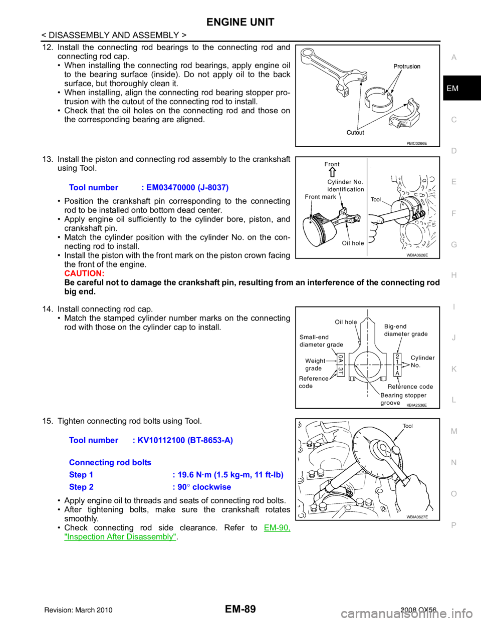
12. Install the connecting rod bearings to the connecting rod and
connecting rod cap.
• When installing the connecting rod bearings, apply engine oilto the bearing surface (inside). Do not apply oil to the back
surface, but thoroughly clean it.
• When installing, align the connecting rod bearing stopper pro-
trusion with the cutout of the connecting rod to install.
• Check that the oil holes on the connecting rod and those on the corresponding bearing are aligned.
13. Install the piston and connecting rod assembly to the crankshaft using Tool.
• Position the crankshaft pin corresponding to the connecting
rod to be installed onto bottom dead center.
• Apply engine oil sufficiently to the cylinder bore, piston, and
crankshaft pin.
• Match the cylinder position with the cylinder No. on the con- necting rod to install.
• Install the piston with the front mark on the piston crown facing the front of the engine.
CAUTION:
Be careful not to damage the crankshaft pin, resu lting from an interference of the connecting rod
big end.
14. Install connecting rod cap. • Match the stamped cylinder number marks on the connectingrod with those on the cylinder cap to install.
15. Tighten connecting rod bolts using Tool. • Apply engine oil to threads and seats of connecting rod bolts.
• After tightening bolts, make sure the crankshaft rotatessmoothly.
• Check connecting rod side clearance. Refer to EM-90,
"Inspection After Disassembly".
PBIC0266E
Tool number : EM03470000 (J-8037)
WBIA0626E
KBIA2536E
Tool number : KV10112100 (BT-8653-A)
Connecting rod bolts
Step 1 : 19.6 N·m (1.5 kg-m, 11 ft-lb)
Step 2: 90° clockwise
WBIA0627E
Revision: March 2010 2008 QX56
Page 1895 of 4083

EM-92
< DISASSEMBLY AND ASSEMBLY >
ENGINE UNIT
(Piston pin clearance) = (Piston pin hole diameter) – (Piston pin
diameter)
• If clearance exceeds specification, replace either or both the pis-
ton/piston pin assembly and the connecting rod assembly with ref-
erence to the specification of each part.
• Use the piston selection table to replace piston/piston pin assem-
bly. Refer to EM-101, "
How to Select Piston and Bearing".
• Use the connecting rod bearing selection table to replace connect- ing rod. Refer to EM-101, "
How to Select Piston and Bearing".
NOTE:
The connecting rod small end grade and piston pin hole (piston
pin) grade are provided only for the parts installed at the plant. For
service parts, no grades can be selected (only 0 grade is avail-
able).
• Follow the "Connecting Rod Bushing Oil Clearance (Small End)" procedure for the values for each grade at the plant.
PISTON RING SIDE CLEARANCE
• Measure side clearance of the piston ring and piston ring grooveusing suitable tool.
• If out of specification, replac e piston and/or piston ring assembly.
PISTON RING END GAP
• Check if the diameter of the cyli nder bore is within specification.
Follow the "Piston to Cylinder Bore Clearance" procedure.
• Insert the piston ring into the middle of the cylinder using the pis- ton, and measure the gap.
• If out of specification, replace pi ston ring. If the gap still exceeds the li mit even with a new ring, re-bore the
cylinder and use oversized piston and piston ring. Standard : 0.002 - 0.006 mm (0.0001 - 0.0002 in)
KBIA2496E
KBIA2536E
Standard:
Top ring : 0.035 - 0.085 mm (0.0014 - 0.0033 in)
2nd ring : 0.030 - 0.070 mm (0.0012 - 0.0028 in)
Oil ring : 0.015 - 0.050 mm (0.0006 - 0.0020 in)
Limit: Top ring : 0.11 mm (0.0043 in)
2nd ring : 0.10 mm (0.0039 in)
SEM024AA
Standard Top ring : 0.23 - 0.33 mm (0.0091 - 0.0130 in)
2nd ring : 0.25 - 0.40 mm (0.0098 - 0.0157 in)
Oil ring : 0.20 - 0.60 mm (0.0079 - 0.0236 in)
Limit: Top ring : 0.56 mm (0.0220 in)
2nd ring : 0.52 mm (0.0205 in)
Oil ring : 0.96 mm (0.0378 in)
PBIC0118E
Revision: March 2010 2008 QX56
Page 1896 of 4083

ENGINE UNITEM-93
< DISASSEMBLY AND ASSEMBLY >
C
DE
F
G H
I
J
K L
M A
EM
NP
O
CONNECTING ROD BEND AND TORSION
• Check connecting rod alignment using suitable tool.
• If measurement exceeds the limi
t, replace connecting rod assem-
bly.
CONNECTING ROD BEARING (BIG END)
• Install the connecting rod cap without the connecting rod bearing installed. After tightening the connecting rod bolt to the specified
torque, measure the connecting rod large end inside diameter.
Refer to EM-82, "
Disassembly and Assembly".
• If measurement exceeds the standard, replace connecting rod.
CONNECTING ROD BUSHING OIL CLEARANCE (SMALL END)
Connecting Rod Inside Diameter (Small End)
• Measure inside diameter of bushing using suitable tool.
Piston Pin Diameter
Limit: Bend: 0.15 mm (0.0059 in) per 100 mm (3.94 in) length
To r s i o n : 0.30 mm (0.0118 in) per 100 mm (3.94 in) length
SEM003F
SEM038F
Standard : 57.000 - 57.013 mm (2.2441 - 2.2446 in)
PBIC1641E
Standard : 22.000 - 22.006 mm (0.8661 - 0.8664 in)
PBIC0120E
Revision: March 2010 2008 QX56
Page 1897 of 4083

EM-94
< DISASSEMBLY AND ASSEMBLY >
ENGINE UNIT
• Measure diameter of piston pin using suitable tool.
Connecting Rod Bushing Oil Clearance (Small End)
(Connecting rod small end oil clearance) = (Inside diameter of con-
necting rod small end) – (Piston pin diameter)
• If measured value exceeds the standard, replace the connectingrod assembly and/or piston and piston pin assembly.
• If replacing the piston and piston pin assembly, use the Table for
Selective Fitting for Piston to select the piston corresponding to the
applicable bore grade of the cylinder block to be used. Refer to
EM-101, "
How to Select Piston and Bearing".
Factory installed parts grading:
• Only grade 0 is available.
Unit: mm (in)
CYLINDER BLOCK DISTORTION
• Remove any oil, scale, gasket, sealant and carbon deposits from the cylinder block surface.
CAUTION:
Do not allow any debris to en ter the oil or coolant passages.
• Measure block upper face for distortion in six directions as shown.
• If measurement exceeds the limit, replace cylinder block.
MAIN BEARING HOUSING INSIDE DIAMETER
Standard : 21.989 - 21.995 mm (0.8657 - 0.8659 in)
PBIC0117E
Standard : 0.005 - 0.017 mm (0.0002 - 0.0007 in)
KBIA2536E
Grade 0
Connecting rod bushing inside diameter 22.000 - 22.006
(0.8661 - 0.8664)
Piston pin diameter 21.989 - 21.995
(0.8657 - 0.8659)
Piston pin hole diameter 21.993 - 21.999
(0.8659 - 0.8661)
KBIA2496E
Standard : 0.03 mm (0.0012 in)
Limit : 0.1 mm (0.004 in)
SEM123C
Revision: March 2010 2008 QX56
Page 1899 of 4083

EM-96
< DISASSEMBLY AND ASSEMBLY >
ENGINE UNIT
• Measure point ″H″.
Piston to Cylinde r Bore Clearance
• Calculate by using diameter of the piston skirt and the cylinder bore diameter (direction X, position B).
(Clearance) = (Cylinder bore diameter) – (piston skirt diameter)
• If calculation exceeds the limit, replace piston/piston pin assembly.
Reboring Cylinder Bore
1. Cylinder bore size is determined by adding pi ston-to-bore clearance to piston diameter “A”.
2. Install main bearing caps, and tighten them to the specified torque. Otherwise, cylinder bores may be dis-
torted in final assembly.
3. Cut the cylinder bores. NOTE:
• When any cylinder needs boring, all other cylinders must also be bored.
• Do not cut too much out of cylinder bore at one time. Cut only 0.05 mm (0.0020 in) or so in diameter at atime.
4. Hone cylinders to obtain the specified piston-to-bore clearance.
5. Measure finished cylinder bore for out-of-round and taper. NOTE:
Measurement should be done after cylinder bore cools down.
CRANKSHAFT JOURNAL DIAMETER
• Measure diameter of crankshaft journals.
• If measurement is out of standard, measure the ma in bearing oil clearance. Then use the undersize bearing.
Follow the "MAIN BEARING OIL CLEARANCE" procedure.
CRANKSHAFT PIN DIAMETER
Distance from the top : 39 mm (1.54 in)
KBIA2545E
Standard : 0.010 - 0.030 mm (0.0004 - 0.0012 in)
Limit : 0.08 mm (0.0031 in)
Rebored size calculation: D = A +B - C
where,
D: Bored diameter
A: Piston diameter as measured
B: Piston - to - bore clearance (standard value)
C: Honing allowance 0.02 mm (0.0008 in)
Standard : 63.940 - 63.964 mm (2.5173 - 2.5183 in)
Revision: March 2010 2008 QX56
Page 1900 of 4083

ENGINE UNITEM-97
< DISASSEMBLY AND ASSEMBLY >
C
DE
F
G H
I
J
K L
M A
EM
NP
O
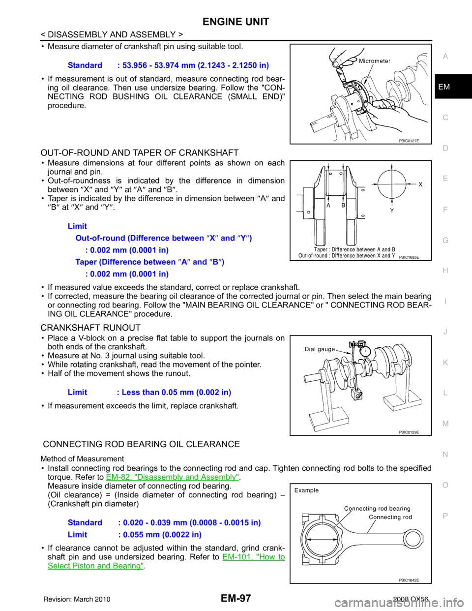
• Measure diameter of crankshaft pin using suitable tool.
• If measurement is out of standard, measure connecting rod bear-
ing oil clearance. Then use undersize bearing. Follow the "CON-
NECTING ROD BUSHING OIL CLEARANCE (SMALL END)"
procedure.
OUT-OF-ROUND AND TAPER OF CRANKSHAFT
• Measure dimensions at four di fferent points as shown on each
journal and pin.
• Out-of-roundness is indicated by the difference in dimension
between ″X″ and ″Y″ at ″A″ and ″B″ .
• Taper is indicated by the difference in dimension between ″A ″ and
″ B″ at ″X ″ and ″Y″ .
• If measured value exceeds the standard, correct or replace crankshaft.
• If corrected, measure the bearing oil clearance of the corrected journal or pin. Then select the main bearing or connecting rod bearing. Follow the "MAIN BEA RING OIL CLEARANCE" or " CONNECTING ROD BEAR-
ING OIL CLEARANCE" procedure.
CRANKSHAFT RUNOUT
• Place a V-block on a precise flat table to support the journals on both ends of the crankshaft.
• Measure at No. 3 journal using suitable tool.
• While rotating crankshaft, read the movement of the pointer.
• Half of the movement shows the runout.
• If measurement exceeds the limit, replace crankshaft.
CONNECTING ROD BEARING OIL CLEARANCE
Method of Measurement
• Install connecting rod bearings to the connecting rod and cap. Tighten connecting rod bolts to the specified
torque. Refer to EM-82, "
Disassembly and Assembly".
Measure inside diameter of connecting rod bearing.
(Oil clearance) = (Inside diameter of connecting rod bearing) –
(Crankshaft pin diameter)
• If clearance cannot be adjusted wit hin the standard, grind crank-
shaft pin and use undersized bearing. Refer to EM-101, "
How to
Select Piston and Bearing".
Standard : 53.956 - 53.974 mm (2.1243 - 2.1250 in)
PBIC0127E
Limit
Out-of-round (Difference between ″X ″ and ″ Y″)
: 0.002 mm (0.0001 in)
Taper (Difference between ″ A″ and ″B ″)
: 0.002 mm (0.0001 in)
PBIC1685E
Limit : Less than 0.05 mm (0.002 in)
PBIC0129E
Standard : 0.020 - 0.039 mm (0.0008 - 0.0015 in)
Limit : 0.055 mm (0.0022 in)
PBIC1642E
Revision: March 2010 2008 QX56
Page 1901 of 4083

EM-98
< DISASSEMBLY AND ASSEMBLY >
ENGINE UNIT
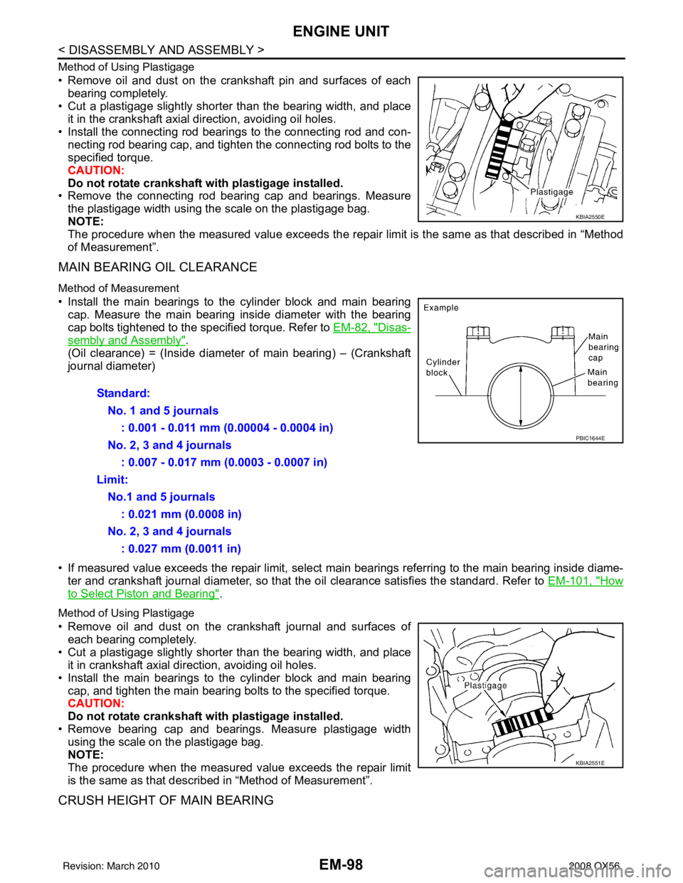
Method of Using Plastigage
• Remove oil and dust on the crankshaft pin and surfaces of eachbearing completely.
• Cut a plastigage slightly shorter than the bearing width, and place
it in the crankshaft axial direction, avoiding oil holes.
• Install the connecting rod beari ngs to the connecting rod and con-
necting rod bearing cap, and tighten the connecting rod bolts to the
specified torque.
CAUTION:
Do not rotate crankshaft with plastigage installed.
• Remove the connecting rod bear ing cap and bearings. Measure
the plastigage width using the scale on the plastigage bag.
NOTE:
The procedure when the measured value exceeds the repair limit is the same as that described in “Method
of Measurement”.
MAIN BEARING OIL CLEARANCE
Method of Measurement
• Install the main bearings to the cylinder block and main bearing cap. Measure the main bearing inside diameter with the bearing
cap bolts tightened to the specified torque. Refer to EM-82, "
Disas-
sembly and Assembly".
(Oil clearance) = (Inside diameter of main bearing) – (Crankshaft
journal diameter)
• If measured value exceeds the repair limit, select main bearings referring to the main bearing inside diame-
ter and crankshaft journal diameter, so that the oil clearance satisfies the standard. Refer to EM-101, "
How
to Select Piston and Bearing".
Method of Using Plastigage
• Remove oil and dust on the crankshaft journal and surfaces of
each bearing completely.
• Cut a plastigage slightly shorter than the bearing width, and place it in crankshaft axial direction, avoiding oil holes.
• Install the main bearings to the cylinder block and main bearing cap, and tighten the main bearing bolts to the specified torque.
CAUTION:
Do not rotate crankshaft with plastigage installed.
• Remove bearing cap and bearings. Measure plastigage width using the scale on the plastigage bag.
NOTE:
The procedure when the measured value exceeds the repair limit
is the same as that descri bed in “Method of Measurement”.
CRUSH HEIGHT OF MAIN BEARING
KBIA2550E
Standard:
No. 1 and 5 journals : 0.001 - 0.011 mm (0.00004 - 0.0004 in)
No. 2, 3 and 4 journals : 0.007 - 0.017 mm (0.0003 - 0.0007 in)
Limit: No.1 and 5 journals : 0.021 mm (0.0008 in)
No. 2, 3 and 4 journals : 0.027 mm (0.0011 in)
PBIC1644E
KBIA2551E
Revision: March 2010 2008 QX56
Page 1924 of 4083

PRECAUTIONSEX-3
< PRECAUTION >
C
DE
F
G H
I
J
K L
M A
EX
NP
O
5. When the repair work is completed, return the ignition switch to the
″LOCK ″ position before connecting
the battery cables. (At this time, the steering lock mechanism will engage.)
6. Perform a self-diagnosis check of al l control units using CONSULT-III.
Precaution for Liquid GasketINFOID:0000000001538868
REMOVAL OF LIQUID GASKET SEALING
• After removing the bolts and nuts, separate the mating surface and
remove the old liquid gasket sealing using Tool.
CAUTION:
Do not damage the mating surfaces.
• Tap the seal cutter to insert it (1).
• In areas where the Tool is difficult to use, lightly tap to slide it (2).
LIQUID GASKET APPLICATION PROCEDURE
1. Remove the old liquid gasket adhering to the gasket application surface and the mating surface using suitable tool.
• Remove the liquid gasket completely from the groove of the
liquid gasket application surface, bolts, and bolt holes.
2. Thoroughly clean the mating surfaces and remove adhering moisture, grease and foreign material.
3. Attach the liquid gasket tube to the Tool. Use Genuine RTV Silicone Sealant or equivalent. Refer to
GI-15, "
Recommended Chemical Products and Sealants".
4. Apply the liquid gasket without breaks to the specified location with the specified dimensions.
• If there is a groove for the liquid gasket application, apply theliquid gasket to the groove.
• As for the bolt holes, normally apply the liquid gasket inside
the holes. If specified in the procedure, it should also be
applied outside the holes.
• Within five minutes of liquid gasket application, install the mat-
ing component.
• If the liquid gasket protrudes, wipe it off immediately.
• Do not retighten after the installation.
• Wait 30 minutes or more after installation before refilling the engine with engine oil and engine coolant.
CAUTION:
If there are specific instructions in this manual, observe them.
Tool number : KV10111100 (J-37228)
WBIA0566E
PBIC0003E
Tool number : WS39930000 ( — )
WBIA0567E
SEM159F
Revision: March 2010
2008 QX56
Page 1935 of 4083

HEADLAMPEXL-7
< FUNCTION DIAGNOSIS >
C
DE
F
G H
I
J
K
M A
B
EXL
N
O P
FUNCTION DIAGNOSIS
HEADLAMP
System DiagramINFOID:0000000001547094
System DescriptionINFOID:0000000001547095
Control of the headlamp system operation is dependent upon the position of the lighting switch (combination
switch). When the lighting switch is placed in the 2nd position, the BCM (body control module) receives input
requesting the headlamps and park lamps to illuminate. Th is input is communicated to the IPDM E/R (intelli-
gent power distribution module engine room) via the CA N communication lines. The CPU (central processing
unit) of the IPDM E/R controls the headlamp high and headl amp low relay coils. When energized, these relays
direct power to the respective headlamps, which then illuminate.
Component Parts LocationINFOID:0000000001547096
Component DescriptionINFOID:0000000001547097
XENON HEADLAMP
A Xenon type headlamp is adapted to the low beam headlamps. Xenon bulbs do not use a filament.
Instead,they produce light when a high voltage current is passed between two tungsten electrodes through a
AWLIA0009GB
1. BCM M18, M20 (view with instrument
panel removed) 2. IPDM E/R E122, E123, E124 3. Combination switch M28
4. Combination meter M23, M24
ALLIA0379ZZ
Revision: March 2010 2008 QX56
Page 2038 of 4083

EXL-110
< ON-VEHICLE REPAIR >
ADJUSTMENT AND INSPECTION
ON-VEHICLE REPAIR
ADJUSTMENT AND INSPECTION
HEADLAMP
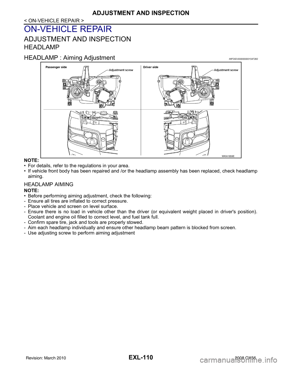
HEADLAMP : Aiming AdjustmentINFOID:0000000001547282
NOTE:
• For details, refer to the regulations in your area.
• If vehicle front body has been repaired and /or the headlamp assembly has been replaced, check headlamp
aiming.
HEADLAMP AIMING
NOTE:
• Before performing aiming adjustment, check the following:
- Ensure all tires are inflated to correct pressure.
- Place vehicle and screen on level surface.
- Ensure there is no load in vehicle other than the driver (or equivalent weight placed in driver's position).
Coolant and engine oil filled to correct level, and fuel tank full.
- Confirm spare tire, jack and tools are properly stowed.
- Aim each headlamp individually and ensure other headlamp beam pattern is blocked from screen.
- Use adjusting screw to perform aiming adjustment
WKIA1859E
Revision: March 2010 2008 QX56