engine oil INFINITI QX56 2008 Factory User Guide
[x] Cancel search | Manufacturer: INFINITI, Model Year: 2008, Model line: QX56, Model: INFINITI QX56 2008Pages: 4083, PDF Size: 81.73 MB
Page 738 of 4083

PRECAUTIONSCO-3
< PRECAUTION >
C
DE
F
G H
I
J
K L
M A
CO
NP
O
5. When the repair work is completed, return the ignition switch to the
″LOCK ″ position before connecting
the battery cables. (At this time, the steering lock mechanism will engage.)
6. Perform a self-diagnosis check of al l control units using CONSULT-III.
Precaution for Liquid GasketINFOID:0000000001538852
REMOVAL OF LIQUID GASKET SEALING
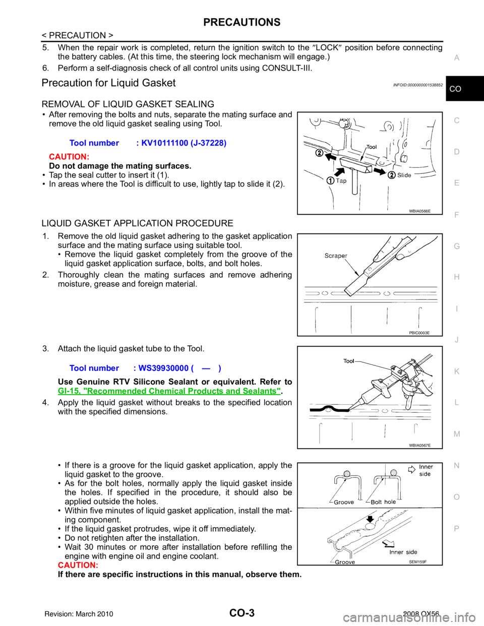
• After removing the bolts and nuts, separate the mating surface and
remove the old liquid gasket sealing using Tool.
CAUTION:
Do not damage the mating surfaces.
• Tap the seal cutter to insert it (1).
• In areas where the Tool is difficult to use, lightly tap to slide it (2).
LIQUID GASKET APPLICATION PROCEDURE
1. Remove the old liquid gasket adhering to the gasket application surface and the mating surface using suitable tool.
• Remove the liquid gasket completely from the groove of the
liquid gasket application surface, bolts, and bolt holes.
2. Thoroughly clean the mating surfaces and remove adhering moisture, grease and foreign material.
3. Attach the liquid gasket tube to the Tool. Use Genuine RTV Silicone Sealant or equivalent. Refer to
GI-15, "
Recommended Chemical Products and Sealants".
4. Apply the liquid gasket without breaks to the specified location with the specified dimensions.
• If there is a groove for the liquid gasket application, apply theliquid gasket to the groove.
• As for the bolt holes, normally apply the liquid gasket inside
the holes. If specified in the procedure, it should also be
applied outside the holes.
• Within five minutes of liquid gasket application, install the mat-
ing component.
• If the liquid gasket protrudes, wipe it off immediately.
• Do not retighten after the installation.
• Wait 30 minutes or more after installation before refilling the engine with engine oil and engine coolant.
CAUTION:
If there are specific instructions in this manual, observe them.
Tool number : KV10111100 (J-37228)
WBIA0566E
PBIC0003E
Tool number : WS39930000 ( — )
WBIA0567E
SEM159F
Revision: March 2010
2008 QX56
Page 739 of 4083

CO-4
< PREPARATION >
PREPARATION
PREPARATION
PREPARATION
Special Service ToolINFOID:0000000001538853
The actual shapes of Kent-Moore tools may differ from those of special service tools illustrated here.
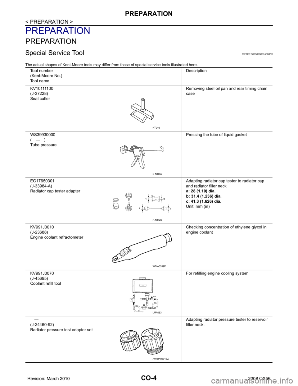
Tool number
(Kent-Moore No.)
Tool name Description
K V 1 0 1111 0 0
(J-37228)
Seal cutter Removing steel oil pan and rear timing chain
case
WS39930000
(—)
Tube pressure Pressing the tube of liquid gasket
EG17650301
(J-33984-A)
Radiator cap tester adapter Adapting radiator cap tester to radiator cap
and radiator filler neck
a: 28 (1.10) dia.
b: 31.4 (1.236) dia.
c: 41.3 (1.626) dia.
Unit: mm (in)
KV991J0010
(J-23688)
Engine coolant refractometer Checking concentration of ethylene glycol in
engine coolant
KV991J0070
(J-45695)
Coolant refill tool For refilling engine cooling system
—
(J-24460-92)
Radiator pressure test adapter set Adapting radiator pressure tester to reservoir
filler neck.
NT046
S-NT052
S-NT564
WBIA0539E
LMA053
AWBIA0891ZZ
Revision: March 2010
2008 QX56
Page 746 of 4083

ENGINE COOLANTCO-11
< ON-VEHICLE MAINTENANCE >
C
DE
F
G H
I
J
K L
M A
CO
NP
O
Changing Engine CoolantINFOID:0000000001538859
WARNING:
• To avoid being scalded, never change the coolant when the engine is hot.
• Wrap a thick cloth around the cap to carefully remo
ve the cap. First, turn the cap a quarter of a turn
to release any built-up pressure, then push down and turn the cap all the way to remove it.
DRAINING ENGINE COOLANT
1. Turn ignition switch ON and set temperature control lever all the way to HOT position or the highest tem-
perature position. Wait 10 seconds and turn ignition switch OFF.
2. Remove the engine front undercover using power tool.
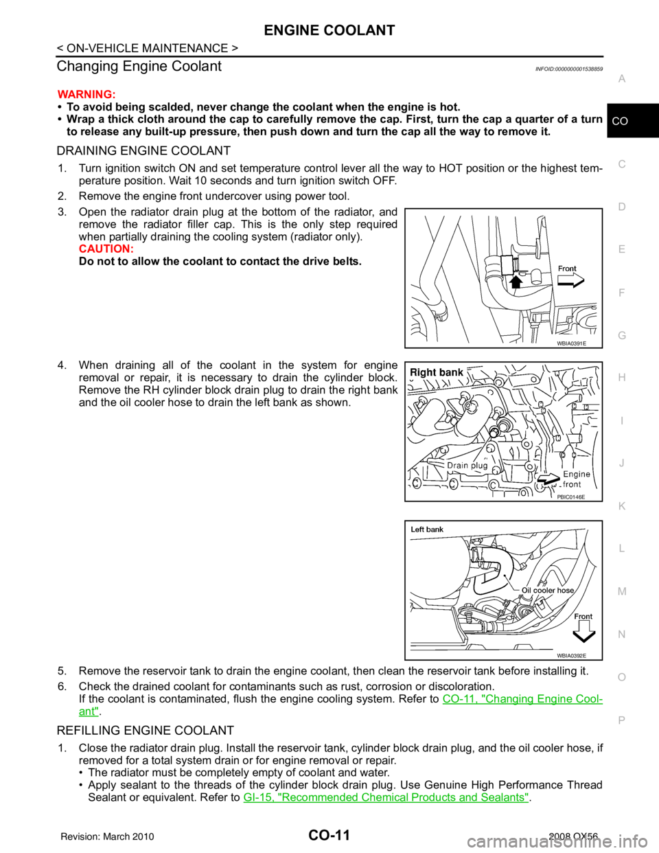
3. Open the radiator drain plug at the bottom of the radiator, and remove the radiator filler cap. This is the only step required
when partially draining the cooling system (radiator only).
CAUTION:
Do not to allow the coolant to contact the drive belts.
4. When draining all of the coolant in the system for engine removal or repair, it is necessary to drain the cylinder block.
Remove the RH cylinder block drain plug to drain the right bank
and the oil cooler hose to drain the left bank as shown.
5. Remove the reservoir tank to drain the engine cool ant, then clean the reservoir tank before installing it.
6. Check the drained coolant for contaminants such as rust, corrosion or discoloration. If the coolant is contaminated, flush the engine cooling system. Refer to CO-11, "
Changing Engine Cool-
ant".
REFILLING ENGINE COOLANT
1. Close the radiator drain plug. Install the reservoir tank, cylinder block drain plug, and the oil cooler hose, if
removed for a total system drain or for engine removal or repair.
• The radiator must be complete ly empty of coolant and water.
• Apply sealant to the threads of the cylinder block drain plug. Use Genuine High Performance Thread Sealant or equivalent. Refer to GI-15, "
Recommended Chemical Products and Sealants".
WBIA0391E
PBIC0146E
WBIA0392E
Revision: March 2010 2008 QX56
Page 753 of 4083

CO-18
< ON-VEHICLE REPAIR >
ENGINE COOLING FAN
ENGINE COOLING FAN
Removal and Installation (Crankshaft Driven Type)INFOID:0000000001538862
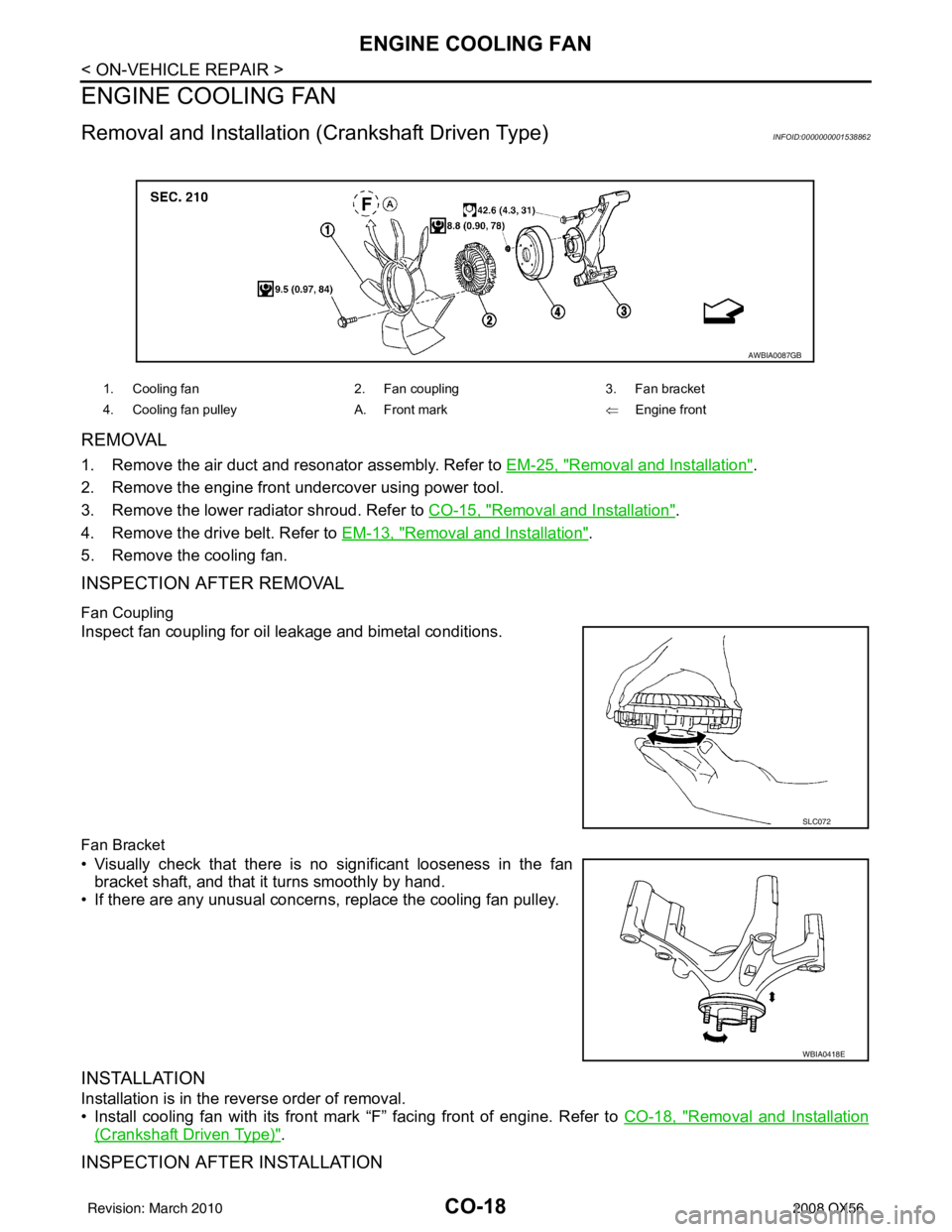
REMOVAL
1. Remove the air duct and resonator assembly. Refer to EM-25, "Removal and Installation".
2. Remove the engine front undercover using power tool.
3. Remove the lower radiator shroud. Refer to CO-15, "
Removal and Installation".
4. Remove the drive belt. Refer to EM-13, "
Removal and Installation".
5. Remove the cooling fan.
INSPECTION AFTER REMOVAL
Fan Coupling
Inspect fan coupling for oil leakage and bimetal conditions.
Fan Bracket
• Visually check that there is no significant looseness in the fan bracket shaft, and that it turns smoothly by hand.
• If there are any unusual concerns, replace the cooling fan pulley.
INSTALLATION
Installation is in the reverse order of removal.
• Install cooling fan with its front mark “F” facing front of engine. Refer to CO-18, "
Removal and Installation
(Crankshaft Driven Type)".
INSPECTION AFTER INSTALLATION
1. Cooling fan 2. Fan coupling3. Fan bracket
4. Cooling fan pulley A. Front mark ⇐Engine front
AWBIA0087GB
SLC072
WBIA0418E
Revision: March 2010 2008 QX56
Page 936 of 4083
![INFINITI QX56 2008 Factory User Guide BCM (BODY CONTROL MODULE)DLK-143
< ECU DIAGNOSIS > [WITH INTELLIGENT KEY SYSTEM]
C
D
E
F
G H
I
J
L
M A
B
DLK
N
O P
HEADLAMP SW1 Headlamp switch OFF OFF
Headlamp switch 1st
ON
HEADLAMP SW2 Headlamp swi INFINITI QX56 2008 Factory User Guide BCM (BODY CONTROL MODULE)DLK-143
< ECU DIAGNOSIS > [WITH INTELLIGENT KEY SYSTEM]
C
D
E
F
G H
I
J
L
M A
B
DLK
N
O P
HEADLAMP SW1 Headlamp switch OFF OFF
Headlamp switch 1st
ON
HEADLAMP SW2 Headlamp swi](/img/42/57030/w960_57030-935.png)
BCM (BODY CONTROL MODULE)DLK-143
< ECU DIAGNOSIS > [WITH INTELLIGENT KEY SYSTEM]
C
D
E
F
G H
I
J
L
M A
B
DLK
N
O P
HEADLAMP SW1 Headlamp switch OFF OFF
Headlamp switch 1st
ON
HEADLAMP SW2 Headlamp switch OFF
OFF
Headlamp switch 1st ON
HI BEAM SW High beam switch OFF
OFF
High beam switch HI ON
IGN ON SW Ignition switch OFF or ACC
OFF
Ignition switch ON ON
IGN SW CAN Ignition switch OFF or ACC
OFF
Ignition switch ON ON
INT VOLUME Wiper intermittent dial is in a dial position 1 - 7 1 - 7
I-KEY LOCK LOCK button of Intelligent Key is not pressed
OFF
LOCK button of Intelligent Key is pressed ON
I-KEY UNLOCK UNLOCK button of Intelligent Key is not pressed
OFF
UNLOCK button of Intelligent Key is pressed ON
KEY ON SW Mechanical key is removed from key cylinder
OFF
Mechanical key is inserted to key cylinder ON
OIL PRESS SW • Ignition switch OFF or ACC
• Engine running
OFF
Ignition switch ON ON
PASSING SW Other than lighting switch PASS
OFF
Lighting switch PASS ON
REAR DEF SW Rear window defogger switch OFF
OFF
Rear window defogger switch ON ON
RR WASHER SW Rear washer switch OFF
OFF
Rear washer switch ON ON
RR WIPER INT Rear wiper switch OFF
OFF
Rear wiper switch INT ON
RR WIPER ON Rear wiper switch OFF
OFF
Rear wiper switch ON ON
RR WIPER STOP Rear wiper stop position
OFF
Other than rear wiper stop position ON
TAIL LAMP SW Lighting switch OFF
OFF
Lighting switch 1ST ON
TRNK OPNR SW When back door opener switch is not pressed
OFF
When back door opener switch is pressed ON
TURN SIGNAL L Turn signal switch OFF
OFF
Turn signal switch LH ON
TURN SIGNAL R Turn signal switch OFF
OFF
Turn signal switch RH ON
VEHICLE SPEED While driving Equivalent to speedo meter reading
Monitor Item
Condition Value/Status
Revision: March 2010 2008 QX56
Page 1044 of 4083
![INFINITI QX56 2008 Factory User Guide DLN-14
< FUNCTION DIAGNOSIS >[ATX14B]
4WD SYSTEM
• Displays 4LO condition while engine is running. 4LO indicator lamp flashes if transfer gear does not shift
completely under 2WD, AUTO, 4H ⇔4LO. ( INFINITI QX56 2008 Factory User Guide DLN-14
< FUNCTION DIAGNOSIS >[ATX14B]
4WD SYSTEM
• Displays 4LO condition while engine is running. 4LO indicator lamp flashes if transfer gear does not shift
completely under 2WD, AUTO, 4H ⇔4LO. (](/img/42/57030/w960_57030-1043.png)
DLN-14
< FUNCTION DIAGNOSIS >[ATX14B]
4WD SYSTEM
• Displays 4LO condition while engine is running. 4LO indicator lamp flashes if transfer gear does not shift
completely under 2WD, AUTO, 4H ⇔4LO. (When 4WD warning lamp is turned on, 4LO indicator lamp is
turned off.)
• Turns ON for approximately 1 second when ignition switch is turned ON, for purpose of lamp check.
4WD WARNING LAMP
Turns on or flashes when there is a malfunction in 4WD system.
Also turns on when ignition switch is turned ON, for purpose of lamp che\
ck. Turns OFF approximately 1 sec-
ond after the engine starts if system is normal.
4WD Warning Lamp Indication
ATP WARNING LAMP
When the A/T selector lever is in P position, the vehicle may move if the transfer case is in neutral. ATP warn-
ing lamp is turned on to indicate this condition to the driver.
LINE PRESSURE SWITCH
• With the transfer system design, control of the oil pressure provides the transmission of drive torque to the
front wheels. The main pressure to control the oil pressure is referred to as the line pressure.
• The line pressure switch determines whether or not adequate line pressure has built up under different oper- ating conditions.
• The line pressure switch closes when line pressure is produced.
• The line pressure switch senses line pressure abnormalities and turns the 4WD warning lamp ON.
CLUTCH PRESSURE SWITCH
• The clutch pressure switch determines whether or not adequate clutch pressure has built up under different
operating conditions.
• The clutch pressure switch closes when clutch pressure is produced.
• The clutch pressure switch senses clutch pressure abnormalities and turns the 4WD warning lamp ON.
WAIT DETECTION SWITCH
• The wait detection switch operates when there is circulating torque produced in the propeller shaft (L→H) or
when there is a phase difference between 2-4 sleeve and clutch drum (H →L). After the release of the circu-
lating torque, the wait detection switch helps provi de the 4WD lock gear (clutch drum) shifts. A difference
may occur between the operation of the 4WD shift swit ch and actual drive mode. At this point, the wait
detection switch senses an actual drive mode.
• The wait detection switch operates as follows.
- 4WD lock gear (clutch drum) locked: ON
- 4WD lock gear (clutch drum) released: OFF
• The wait detection switch senses an actual drive mode and the 4WD shift indicator lamp indicates the vehi-
cle drive mode.
ATP SWITCH
ATP switch detects if transfer case is in neutral by the position of the L-H shift fork.
NOTE:
Transfer case may be in neutral when shifting between 4H-4LO.
NEUTRAL-4LO SWITCH
The neutral-4LO switch detects that transfer gear is in neutral or 4LO (or shifting from neutral to 4LO) condi-
tion by L-H shift fork position.
Condition 4WD warning lamp
System normal OFF
Lamp check Turns ON when ignition switch is turned ON.
Turns OFF after engine start.
4WD system malfunction ON
During self-diagnosis Flashes malfunction mode.
Large difference in diameter of front/
rear tires Flashes slow (1 flash / 2 seconds)
(Continues to flash until the ignition switch is turned OFF)
High fluid temperature in transfer case Flashes rapidly (2 flashes / 1 second)
(Continues to flash until fluid temperature returns to normal)
Revision: March 2010 2008 QX56
Page 1097 of 4083
![INFINITI QX56 2008 Factory User Guide P1826 TRANSFER FLUID TEMPERATUREDLN-67
< COMPONENT DIAGNOSIS > [ATX14B]
C
EF
G H
I
J
K L
M A
B
DLN
N
O P
P1826 TRANSFER FLUID TEMPERATURE
DescriptionINFOID:0000000001737155
Signal voltage from the tra INFINITI QX56 2008 Factory User Guide P1826 TRANSFER FLUID TEMPERATUREDLN-67
< COMPONENT DIAGNOSIS > [ATX14B]
C
EF
G H
I
J
K L
M A
B
DLN
N
O P
P1826 TRANSFER FLUID TEMPERATURE
DescriptionINFOID:0000000001737155
Signal voltage from the tra](/img/42/57030/w960_57030-1096.png)
P1826 TRANSFER FLUID TEMPERATUREDLN-67
< COMPONENT DIAGNOSIS > [ATX14B]
C
EF
G H
I
J
K L
M A
B
DLN
N
O P
P1826 TRANSFER FLUID TEMPERATURE
DescriptionINFOID:0000000001737155
Signal voltage from the transfer fluid temperature sens or is abnormally high (Transfer fluid temperature is
abnormally low) while driving.
DTC LogicINFOID:0000000001737156
DTC DETECTION LOGIC
DTC CONFIRMATION PROCEDURE
1.DTC CONFIRMATION PROCEDURE
1. Turn ignition switch ON.
2. Perform self-diagnosis.
Is DTC P1826 displayed?
YES >> Perform diagnosis procedure. Refer to DLN-67, "Diagnosis Procedure".
NO >> Inspection End.
Diagnosis ProcedureINFOID:0000000001737157
1.CHECK TRANSFER FLUID TE MPERATURE SENSOR SIGNAL
With CONSULT-III
1. Start engine.
2. Select DATA MONITOR mode for ALL MODE AWD/4WD with CONSULT-III.
3. Read out the value of FLUID TEMP SE.
Without CONSULT-III
1. Start engine.
2. Check voltage between transfer control unit harness connector
terminals and ground.
Are inspection results normal?
YES >> GO TO 4.
NO >> GO TO 2.
2.CHECK HARNESS BETWEEN TRANSF ER CONTROL UNIT AND TRANSFER TERMINAL CORD AS-
DTCCONSULT-III Diagnostic item is detected when... Reference
[P1826] OIL TEMP SEN Signal voltage from transfer fluid temper-
ature sensor is abnormally high (Trans-
fer fluid temperature is abnormally low)
while driving.Refer to DLN-67
.
Condition
Display value
(Approx.)
Transfer fluid temperature approx. 20 - 80 °C (68 - 176° F) 1.1 - 0.3V
Connector Terminal ConditionData
(Approx.)
E143 28 -
Ground Always
0V
31 -
Ground Ignition switch:
ON Transfer fluid temperature
approx. 20
°C (68 °F) 1.1V
Transfer fluid temperature
approx. 80 °C (176 °F) 0.3V
SDIA2742E
Revision: March 2010
2008 QX56
Page 1156 of 4083
![INFINITI QX56 2008 Factory User Guide DLN-126
< ON-VEHICLE MAINTENANCE >[ATX14B]
TRANSFER OIL FILTER
3. Apply ATF to the two new O-rings (1), and install them on the oil
filter (2).
CAUTION:
Do not reuse O-rings.
4. Install the oil filter INFINITI QX56 2008 Factory User Guide DLN-126
< ON-VEHICLE MAINTENANCE >[ATX14B]
TRANSFER OIL FILTER
3. Apply ATF to the two new O-rings (1), and install them on the oil
filter (2).
CAUTION:
Do not reuse O-rings.
4. Install the oil filter](/img/42/57030/w960_57030-1155.png)
DLN-126
< ON-VEHICLE MAINTENANCE >[ATX14B]
TRANSFER OIL FILTER
3. Apply ATF to the two new O-rings (1), and install them on the oil
filter (2).
CAUTION:
Do not reuse O-rings.
4. Install the oil filter to the transfer assembly. Tighten the bolts to the specified torque. Refer to DLN-125, "
Removal and Installa-
tion".
CAUTION:
• Do not damage oil filter.
• Attach oil filter an d tighten bolts evenly.
5. Check the transfer fluid. Refer to DLN-127, "
Inspection".
6. Start the engine for one minute. Then stop the engine and recheck the transfer fluid. Refer to DLN-127, "
Inspection".
WDIA0285E
SDIA2136E
Revision: March 2010 2008 QX56
Page 1168 of 4083
![INFINITI QX56 2008 Factory User Guide DLN-138
< ON-VEHICLE REPAIR >[ATX14B]
TRANSFER MOTOR
TRANSFER MOTOR
Removal and InstallationINFOID:0000000001604418
REMOVAL
1. Disconnect the transfer motor connector.
2. Remove the transfer motor air INFINITI QX56 2008 Factory User Guide DLN-138
< ON-VEHICLE REPAIR >[ATX14B]
TRANSFER MOTOR
TRANSFER MOTOR
Removal and InstallationINFOID:0000000001604418
REMOVAL
1. Disconnect the transfer motor connector.
2. Remove the transfer motor air](/img/42/57030/w960_57030-1167.png)
DLN-138
< ON-VEHICLE REPAIR >[ATX14B]
TRANSFER MOTOR
TRANSFER MOTOR
Removal and InstallationINFOID:0000000001604418
REMOVAL
1. Disconnect the transfer motor connector.
2. Remove the transfer motor air breather hose from the transfer
motor. Refer to DLN-135, "
Removal and Installation".
3. Remove the transfer motor bolts.
4. Remove the transfer motor.
INSTALLATION
1. Apply ATF to the new O-ring and install it to the transfer motor. CAUTION:
Do not reuse O-rings.
2. Fit the double-flat end of the transfer motor shaft into the slot of the sub-oil pump assembly. Then tighten to the specified torque.
Refer to DLN-140, "
Disassembly and Assembly".
CAUTION:
Be sure to install connector bracket.
3. Install the transfer motor air breather hose to the transfer motor. Refer to DLN-135, "
Removal and Installation".
4. Connect the transfer motor connector.
5. Check the transfer fluid. Refer to DLN-127, "
Inspection".
6. Start the engine for one minute. Then stop the engine and recheck the transfer fluid. Refer to DLN-127,
"Inspection".
SDIA2133E
SDIA2787E
Revision: March 2010 2008 QX56
Page 1169 of 4083
![INFINITI QX56 2008 Factory User Guide TRANSFER ASSEMBLYDLN-139
< REMOVAL AND INSTALLATION > [ATX14B]
C
EF
G H
I
J
K L
M A
B
DLN
N
O P
REMOVAL AND INSTALLATION
TRANSFER ASSEMBLY
Removal and InstallationINFOID:0000000001604419
REMOVAL
1. Se INFINITI QX56 2008 Factory User Guide TRANSFER ASSEMBLYDLN-139
< REMOVAL AND INSTALLATION > [ATX14B]
C
EF
G H
I
J
K L
M A
B
DLN
N
O P
REMOVAL AND INSTALLATION
TRANSFER ASSEMBLY
Removal and InstallationINFOID:0000000001604419
REMOVAL
1. Se](/img/42/57030/w960_57030-1168.png)
TRANSFER ASSEMBLYDLN-139
< REMOVAL AND INSTALLATION > [ATX14B]
C
EF
G H
I
J
K L
M A
B
DLN
N
O P
REMOVAL AND INSTALLATION
TRANSFER ASSEMBLY
Removal and InstallationINFOID:0000000001604419
REMOVAL
1. Set transfer state as 2WD when 4WD shift switch is at 2WD.
2. Remove the undercovers using power tool.
3. Drain the transfer fluid. Refer to DLN-127, "
Replacement".
4. Remove the center exhaust tube and main muffler. Refer to EX-6, "
Removal and Installation".
5. Remove the front and rear propeller shafts. Refer to DLN-184, "
Removal and Installation" (front), DLN-
184, "Removal and Installation" (rear).
CAUTION:
Do not damage spline, sleeve yoke and rear oi l seal when removing rear propeller shaft.
NOTE:
Insert a plug into the rear oil seal after removing the rear propeller shaft.
6. Remove the A/T nuts from the A/T crossmember. Refer to TM-216, "
Removal and Installation (4WD)".
7. Position two suitable jacks under the A/T and transfer assembly.
8. Remove the crossmember. Refer to TM-216, "
Removal and Installation (4WD)".
WARNING:
Support A/T and transfer assembly using two suitable jacks while removing crossmember.
9. Disconnect the electrical connectors from the following: • ATP switch
• Neutral 4LO switch
• Wait detection switch
• Transfer motor
• Transfer control device
• Transfer terminal cord assembly
10. Disconnect each air breather hose from the following. Refer to DLN-135, "
Removal and Installation".
• Actuator
• Breather tube (transfer)
• Transfer motor
11. Remove the transfer control dev ice from the extension housing.
12. Remove the transfer to A/T and A/T to transfer bolts.
13. Remove the transfer assembly. WARNING:
Support transfer assembly with su itable jack while removing it.
CAUTION:
Do not damage rear oil seal (A/T).
INSTALLATION
Installation is in the reverse order of removal.
• Tighten the bolts to specification.
• Fill the transfer with new fluid and check for fluid leakage and fluid level. Refer to DLN-127, "
Replacement".
• Start the engine for one minute. Then stop the engine and recheck the transfer fluid. Refer to DLN-127, "
Inspection".
Transfer bolt torque : 36 N·m (3.7 kg-m, 27 ft-lb)
SMT872C
Revision: March 2010
2008 QX56