Stop INFINITI QX56 2008 Factory Service Manual
[x] Cancel search | Manufacturer: INFINITI, Model Year: 2008, Model line: QX56, Model: INFINITI QX56 2008Pages: 4083, PDF Size: 81.73 MB
Page 2061 of 4083

EXT-8
< SERVICE INFORMATION >
SQUEAK AND RATTLE TROUBLE DIAGNOSES
Most of these incidents can be repaired by adjusting, securing or insulating the item(s) or component(s) caus-
ing the noise.
SUNROOF/HEADLINING
Noises in the sunroof/headlining area c an often be traced to one of the following:
1. Sunroof lid, rail, linkage or seals making a rattle or light knocking noise
2. Sun visor shaft shaking in the holder
3. Front or rear windshield touching headliner and squeaking
Again, pressing on the components to stop the noise while duplicating the conditions can isolate most of these
incidents. Repairs usually consist of insulating with felt cloth tape.
OVERHEAD CONSOLE (FRONT AND REAR)
Overhead console noises are often caused by the c onsole panel clips not being engaged correctly. Most of
these incidents are repaired by pushing up on the c onsole at the clip locations until the clips engage.
In addition look for:
1. Loose harness or harness connectors.
2. Front console map/reading lamp lens loose.
3. Loose screws at console attachment points.
SEATS
When isolating seat noise it's important to note the pos ition the seat is in and the load placed on the seat when
the noise is present. These conditions should be duplicated when verifying and isolating the cause of the
noise.
Cause of seat noise include:
1. Headrest rods and holder
2. A squeak between the seat pad cushion and frame
3. The rear seatback lock and bracket
These noises can be isolated by moving or pressing on the suspected components while duplicating the con-
ditions under which the noise occurs. Most of thes e incidents can be repaired by repositioning the component
or applying urethane tape to the contact area.
UNDERHOOD
Some interior noise may be caused by components under the hood or on the engine wall. The noise is then
transmitted into the passenger compartment.
Causes of transmitted underhood noise include:
1. Any component installed to the engine wall
2. Components that pass through the engine wall
3. Engine wall mounts and connectors
4. Loose radiator installation pins
5. Hood bumpers out of adjustment
6. Hood striker out of adjustment
These noises can be difficult to isolate since they cannot be reached from the interior of the vehicle. The best
method is to secure, move or insulate one component at a time and test drive the \
vehicle. Also, engine RPM
or load can be changed to isolate the noise. Repairs can usually be made by moving, adjusting, securing, or
insulating the component causing the noise.
Revision: March 2010 2008 QX56
Page 2079 of 4083

EXT-26
< SERVICE INFORMATION >
REAR SPOILER
REAR SPOILER
Removal and InstallationINFOID:0000000001609860
Removal
1. Disconnect the negative and positive battery terminals, then wait at least 3 minutes.
2. Remove the back door trim. Refer to INT-21, "
Removal and Installation".
3. Disconnect the harness to high-mount stop lamp.
4. Disconnect the washer tube.
5. Remove the nuts, release the clips and remove the rear spoiler. • Release adhesive tape with sawing motion from monofilament line that has knots in it.
• Remove residue of adhesive tape completely from v ehicle surface with strip-off wheel or equivalent.
CAUTION:
• Never apply tack-paper adhesive remover to bo dy panel surface finished with lacquer-based
paints.
• Use care not to damage the vehicle surf ace during adhesive tape residue removal.
6. Remove the nuts and remove the high-mount stop lamp.
Installation
Installation is in the reverse order of removal.
NOTE:
Apply adhesion promoter only to areas of rear spoiler that tape will be applied, as required.
1. Grommet2. Clip C1013. Nut
4. Rear air spoiler 5. High-mount stop lamp
WIIA0961E
Revision: March 2010 2008 QX56
Page 2095 of 4083

DRIVE SHAFTFAX-11
< DISASSEMBLY AND ASSEMBLY >
CEF
G H
I
J
K L
M A
B
FA X
N
O P
DISASSEMBLY AND ASSEMBLY
DRIVE SHAFT
Disassembly and AssemblyINFOID:0000000001534461
DISASSEMBLY
Final Drive Side
1. Mount the drive shaft in a vise. CAUTION:
When mounting the drive shaft in a vise, use co pper or aluminum plates between the vise and the
drive shaft.
2. Remove the boot bands.
3. Remove the stopper ring using suitable tool as shown, and pull the housing off.
1. Sliding joint housing 2. Snap ring 3. Ball cage, steel ball, inner race assembly
4. Stopper ring 5. Boot band6. Boot
7. Drive shaft 8. Circlip9. Joint sub-assembly
WDIA0054E
SRA249A
Revision: March 2010 2008 QX56
Page 2097 of 4083

DRIVE SHAFTFAX-13
< DISASSEMBLY AND ASSEMBLY >
CEF
G H
I
J
K L
M A
B
FA X
N
O P
• Check the ball sliding surface for any co mpression scars, cracks, or fractures.
• Check for any damage to the serrated part. CAUTION:
If any defective conditions are found, install a new housing, ball cage, steel ball, and inner race as a
set.
ASSEMBLY
Final Drive Side
1. Wrap the serrated part of the drive shaft with tape. Install the boot band and boot to drive shaft.
NOTE:
Discard the old boot band and boot and use a new one for
assembly.
2. Remove the tape wound around the serrated part of the drive shaft.
3. Install the ball cage, steel ball, and inner race assembly on the drive shaft, and secure them tightly using the snap ring.
NOTE:
Discard the old snap ring and use a new one for assembly.
4. Insert the specified quantity of Genuine NISSAN Grease or equivalent, onto the housing (indicated by * marks), and install it
onto shaft. Refer to MA-12, "
Fluids and Lubricants".
5. Install the stopper ring onto the housing.
6. After installation, pull on the shaft to check engagement between the sliding joint and the stopper ring.
SFA800
SDIA1125E
Grease capacity : 130 − 150 g (4.58 − 5.29 oz)
RAC0678D
Revision: March 2010 2008 QX56
Page 2104 of 4083

FL-4
< PRECAUTION >
FUEL SYSTEM
FUEL SYSTEM
General PrecautionINFOID:0000000001534428
WARNING:
When replacing fuel line parts, be sure to observe the following.
• Put a “CAUTION: INFLAMMABLE” sign in the workshop.
• Be sure to work in a well ventilate d area and furnish workshop with a CO
2 fire extinguisher.
• Do not smoke while servicing fuel system. Keep open flames and sparks away from the work area.
CAUTION:
• Before removing fuel line parts, carry out the following procedures:
- Put drained fuel in an explosi on-proof container and put the lid on securely. Keep the container in
safe area.
- Release fuel pressure from the fuel lines. Refer to EC-494, "
Fuel Pressure Check" .
- Disconnect the battery negative terminal.
• Always replace O-rings and clamps with new ones.
• Do not kink or twist hoses when they are being installed.
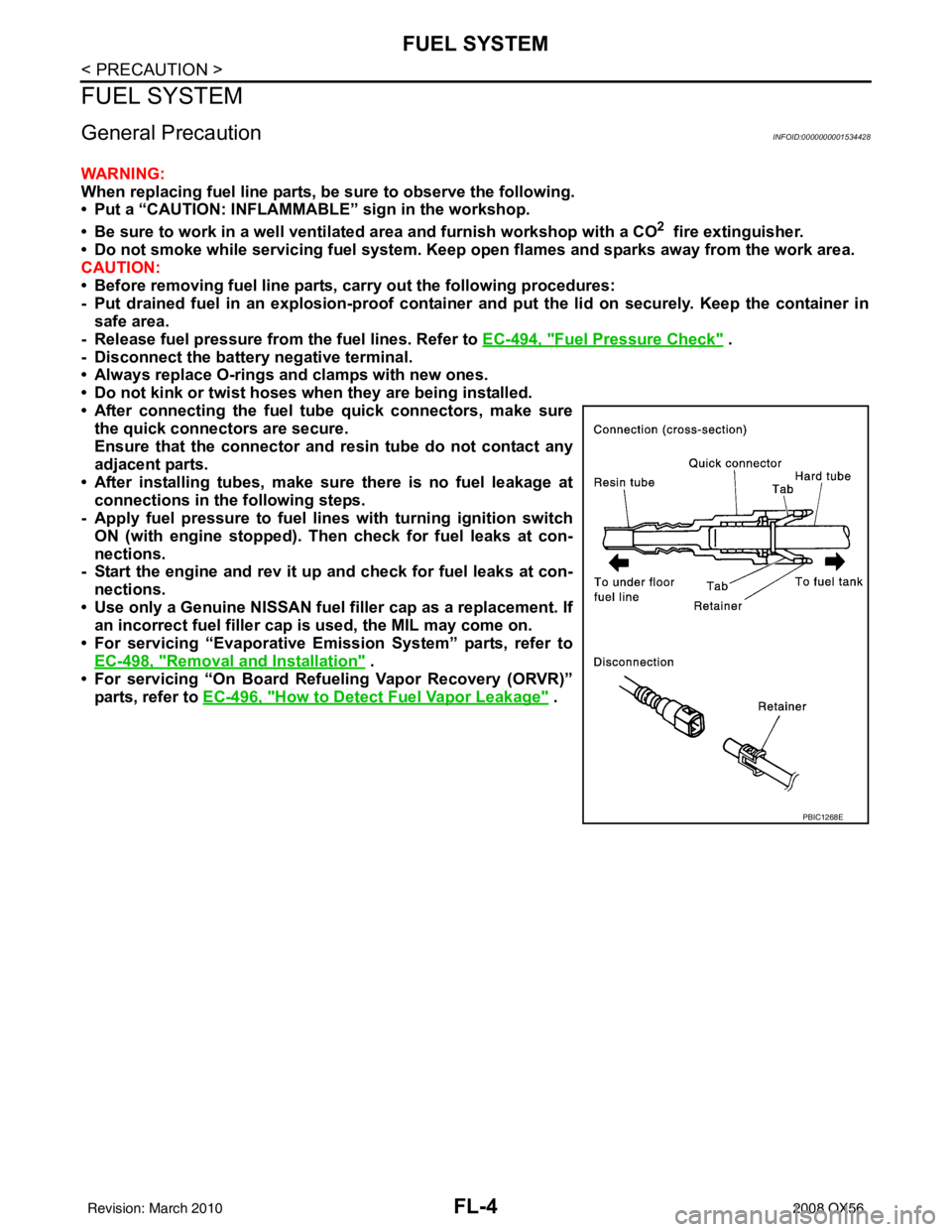
• After connecting the fuel t ube quick connectors, make sure
the quick connectors are secure.
Ensure that the connector and resin tube do not contact any
adjacent parts.
• After installing tubes, make su re there is no fuel leakage at
connections in the following steps.
- Apply fuel pressure to fuel lines with turning ignition switch
ON (with engine stopped). Th en check for fuel leaks at con-
nections.
- Start the engine and rev it up and check for fuel leaks at con-
nections.
• Use only a Genuine NISSAN fuel filler cap as a replacement. If an incorrect fuel filler cap is used, the MIL may come on.
• For servicing “Evaporative Emission System” parts, refer to EC-498, "
Removal and Installation" .
• For servicing “On Board Refueling Vapor Recovery (ORVR)”
parts, refer to EC-496, "
How to Detect Fuel Vapor Leakage" .
PBIC1268E
Revision: March 2010 2008 QX56
Page 2170 of 4083

GI-28
< PRECAUTION >
PRECAUTIONS
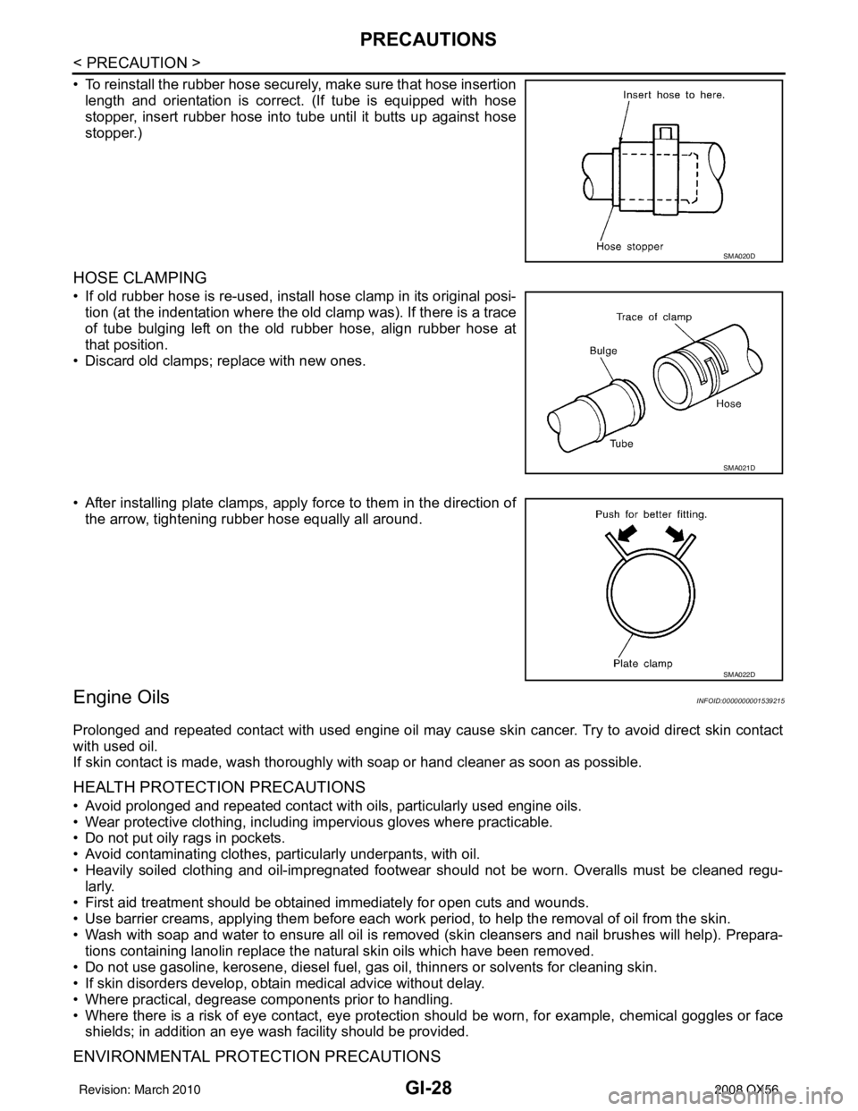
• To reinstall the rubber hose securely, make sure that hose insertionlength and orientation is correct. (If tube is equipped with hose
stopper, insert rubber hose into tube until it butts up against hose
stopper.)
HOSE CLAMPING
• If old rubber hose is re-used, install hose clamp in its original posi-tion (at the indentation where the old clamp was). If there is a trace
of tube bulging left on the old rubber hose, align rubber hose at
that position.
• Discard old clamps; replace with new ones.
• After installing plate clamps, apply force to them in the direction of the arrow, tightening rubber hose equally all around.
Engine OilsINFOID:0000000001539215
Prolonged and repeated contact with used engine oil may cause skin cancer. Try to avoid direct skin contact
with used oil.
If skin contact is made, wash thoroughly with soap or hand cleaner as soon as possible.
HEALTH PROTECTION PRECAUTIONS
• Avoid prolonged and repeated contact with oils, particularly used engine oils.
• Wear protective clothing, including impervious gloves where practicable.
• Do not put oily rags in pockets.
• Avoid contaminating clothes, pa rticularly underpants, with oil.
• Heavily soiled clothing and oil-impregnated footwear should not be worn. Overalls must be cleaned regu- larly.
• First aid treatment should be obtained immediately for open cuts and wounds.
• Use barrier creams, applying them before each work period, to help the removal of oil from the skin.
• Wash with soap and water to ensure all oil is removed (skin cleansers and nail brushes will help). Prepara-
tions containing lanolin replace the natural skin oils which have been removed.
• Do not use gasoline, kerosene, diesel fuel, gas oil, thinners or solvents for cleaning skin.
• If skin disorders develop, obtain medical advice without delay.
• Where practical, degrease components prior to handling.
• Where there is a risk of eye contact, eye protection should be worn, for example, chemical goggles or face
shields; in addition an eye wash facility should be provided.
ENVIRONMENTAL PROTECTION PRECAUTIONS
SMA020D
SMA021D
SMA022D
Revision: March 2010 2008 QX56
Page 2196 of 4083

GW-6
< ON-VEHICLE REPAIR >
WINDSHIELD GLASS
WARNING:
• Keep heat and open flames away as primers and adhesive are flammable.
• The materials contained in the kit are harmful if swallowed, and may irritate skin and eyes. Avoid
contact with the skin and eyes.
• Use in an open, well ventilated location. Avoid breathing the vapors. They can be harmful if inhaled. If affected by vapor inhalation, imme diately move to an area with fresh air.
• Driving the vehicle before the urethane adhesive has completely cured may affect the performance of the windshield in case of an accident.
CAUTION:
• Do not use an adhesive which is past its usable te rm. Shelf life of this product is limited to six
months after the date of manufacture. Carefully a dhere to the expiration or manufacture date printed
on the box.
• Keep primers and adhesive in a c ool, dry place. Ideally, they should be stored in a refrigerator.
• Do not leave primers or adhesive cartridge unattended with their caps open or off.
• The vehicle should not be driven for at least 24 hours or until the urethane adhesive has completely cured. Curing time varies depending on temperature and humidities. The cu ring time will increase
under lower temperatures and lower humidities.
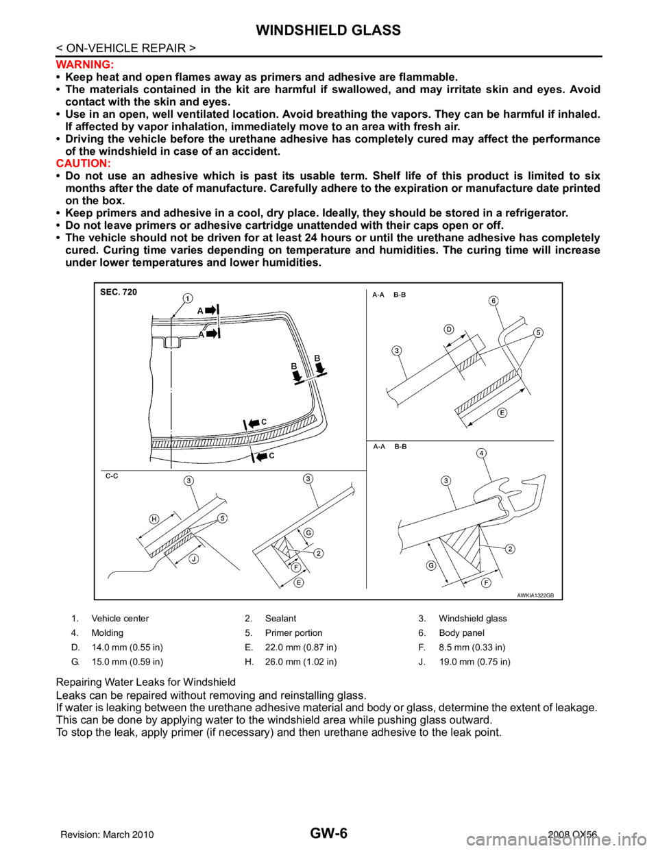
Repairing Water Leaks for Windshield
Leaks can be repaired without removing and reinstalling glass.
If water is leaking between the urethane adhesive material and body or glass, determine the extent of leakage.
This can be done by applying water to the windshield area while pushing glass outward.
To stop the leak, apply primer (if necessary) and then urethane adhesive to the leak point.
1. Vehicle center 2. Sealant3. Windshield glass
4. Molding 5. Primer portion 6. Body panel
D. 14.0 mm (0.55 in) E. 22.0 mm (0.87 in) F. 8.5 mm (0.33 in)
G. 15.0 mm (0.59 in) H. 26.0 mm (1.02 in)J. 19.0 mm (0.75 in)
AWKIA1322GB
Revision: March 2010 2008 QX56
Page 2229 of 4083

HA-24
< ON-VEHICLE MAINTENANCE >
FLUORESCENT LEAK DETECTOR
FLUORESCENT LEAK DETECTOR
Checking of Refrigerant LeaksINFOID:0000000001516646
PRELIMINARY CHECK
Perform a visual inspection of all refrigeration parts, fittings, hoses and components for signs of A/C oil leak-
age, damage, and corrosion. Any A/C oil leakage may indicate an area of refrigerant leakage. Allow extra
inspection time in these areas when using either an el ectronic refrigerant leak detector (J-41995) or fluores-
cent dye leak detector (J-42220).
If any dye is observed using a fluorescent dye leak detector (J-42220), confirm the leak using a electronic
refrigerant leak detector (J-41995). It is possible that the dye is from a prior leak that was repaired and not
properly cleaned.
When searching for leaks, do not stop when one leak is found but continue to check for additional leaks at all
system components and connections.
When searching for refrigerant leaks using an electronic refrigerant leak detector (J-41995), move the probe
along the suspected leak area at 25 - 50 mm (1 - 2 in) per second and no further than 6 mm (1/4 in) from the
component.
CAUTION:
Moving the electronic refrigerant l eak detector probe slower and closer to the suspected leak area will
improve the chances of finding a leak.
Checking System for L eaks Using the Fluorescent Dye Leak DetectorINFOID:0000000001516647
1. Check the A/C system for leaks using the fluorescent dye leak detector and safety goggles (J-42220) in a
low sunlight area (area without windows preferable). Il luminate all components, fittings and lines. The dye
will appear as a bright green/yellow area at the point of leakage. Fluorescent dye observed at the evapo-
rator drain opening indicates an evaporator core asse mbly leak (tubes, core or expansion valve).
2. If the suspected area is difficult to see, use an adjustable mirror or wipe the area with a clean shop rag or cloth, then inspect the shop rag or cloth with the fl uorescent dye leak detector (J-42220) for dye residue.
3. After the leak is repaired, remove any residual dye using refrigerant dye cleaner (J-43872) to prevent
future misdiagnosis.
4. Perform a system performance check and then verify t he leak repair using a electronic refrigerant leak
detector (J-41995).
NOTE:
• Other gases in the work area or substances on the A/C components, for example, anti-freeze, wind-
shield washer fluid, solvents and oils, may falsely tri gger the leak detector. Make sure the surfaces to be
checked are clean.
• Clean with a dry cloth or blow off with shop air.
• Do not allow the sensor tip of the electronic refri gerant leak detector (J-41995) to contact with any sub-
stance. This can also cause false readings and may damage the detector.
Dye InjectionINFOID:0000000001516648
NOTE:
This procedure is only necessary when recharging the system or when the compressor has seized and must
be replaced.
1. Check the A/C system static (at rest) pressure . Pressure must be at least 345 kPa (3.52 kg/cm
2 , 50 psi).
2. Pour one bottle 7.4 cc (1/4 ounce) of the HFC-134a (R -134a) fluorescent leak detection dye (J-41447) into
the HFC-134a (R-134a) dye injector (J-41459).
CAUTION:
If repairing the A/C system or replacing a co mponent, pour the HFC-134a (R-134a) fluorescent leak
detection dye (J-41447) directly into the open system connection and proceed with the service
procedures.
3. Connect the refrigerant dye injector (J-41459) to the low-pressure service valve.
4. Start the engine and switch the A/C system ON.
5. When the A/C system is operating (compressor running), inject one bottle 7.4 cc (1/4 ounce) of HFC-134a (R-134a) fluorescent leak detection dye (J-41447) through the low-pressure service valve using HFC-
134a (R-134a) dye injector (J-41459). Refer to the manufacturer's operating instructions.
Revision: March 2010 2008 QX56
Page 2231 of 4083

HA-26
< ON-VEHICLE MAINTENANCE >
ELECTRICAL LEAK DETECTOR
ELECTRICAL LEAK DETECTOR
Checking of Refrigerant LeaksINFOID:0000000001516649
PRELIMINARY CHECK
Perform a visual inspection of all refrigeration parts, fittings, hoses and components for signs of A/C oil leak-
age, damage, and corrosion. Any A/C oil leakage may indicate an area of refrigerant leakage. Allow extra
inspection time in these areas when using either an el ectronic refrigerant leak detector (J-41995) or fluores-
cent dye leak detector (J-42220).
If any dye is observed using a fluorescent dye leak detector (J-42220), confirm the leak using a electronic
refrigerant leak detector (J-41995). It is possible that the dye is from a prior leak that was repaired and not
properly cleaned.
When searching for leaks, do not stop when one leak is found but continue to check for additional leaks at all
system components and connections.
When searching for refrigerant leaks using an electronic refrigerant leak detector (J-41995), move the probe
along the suspected leak area at 25 - 50 mm (1 - 2 in) per second and no further than 6 mm (1/4 in) from the
component.
CAUTION:
Moving the electronic refrigerant l eak detector probe slower and closer to the suspected leak area will
improve the chances of finding a leak.
Electronic Refrigerant Leak DetectorINFOID:0000000001516650
PRECAUTIONS FOR HANDLING LEAK DETECTOR
NOTE:
When performing a refrigerant leak check, use a electr onic refrigerant leak detector (J-41995) or equivalent.
Ensure that the electronic refrigerant leak detector (J-41995) is calibrated and set properly according to the
manufacturer's operating instructions.
The electronic refrigerant leak detector (J-41995) is a delicate
device. To use the electronic refrigerant leak detector (J-41995)
properly, read the manufacturer's operating instructions and perform
any specified maintenance.
1. Position the probe approximately 5 mm (3/16 in) away from the point to be checked as shown.
AHA281A
SHA707EA
Revision: March 2010 2008 QX56
Page 2233 of 4083

HA-28
< ON-VEHICLE MAINTENANCE >
ELECTRICAL LEAK DETECTOR
Keep the probe inserted for at least 10 seconds. Use caution not to contaminate the probe tip with water
or dirt that may be in the drain hose.
5. If a leak is detected, verify at least once by blowing compressed air into the area of the suspected leak, then repeat the leak check.
6. Do not stop when one leak is found. Continue to check for additional leaks at all system components and connections.
7. If no leaks are found, perform steps 8 - 11.
8. Start the engine.
9. Set the heater A/C controls as follows: NOTE:
For the automatic system, turn OF F the automatic controls and set the heater A/C controls manually.
a. A/C switch to ON
b. Air flow to VENT mode
c. Intake position to RECIRCULATION mode
d. Temperature to MAX cold
e. Blower fan speed to HIGH
10. Run the engine at 1,500 rpm for at least 2 minutes.
11. Turn the engine OFF and perform the leak check again following steps 4 through 6 above.
Refrigerant leaks should be checked immediately after turning
the engine OFF. Begin with the leak detector at the compressor.
The pressure on the high pressure side will gradually drop after
the refrigerant circulation stops and pressure on the low pres-
sure side will gradually rise, as shown in the graph. Some leaks
are more easily detected when the pressure is high.
12. Before connecting the recovery/recycling equipment to the vehicle, check the recovery/recycling equip-
ment gauges. No refrigerant pressure should be displayed. If pressure is displayed, recover the refriger-
ant from the equipment lines and t hen check the refrigerant purity.
13. Confirm refrigerant purity in supply tank using recovery/recycling equipment and refrigerant identifier
equipment (J-41810-NI).
14. Confirm the refrigerant purity in the vehicle's A/C system using recovery/recycling equipment and refriger-
ant identifier equipment (J-41810-NI).
15. Discharge the A/C system using recovery/recycling equipment. Repair the leaking fitting or component as
necessary.
16. Evacuate and recharge the A/C system and perform the leak test to confirm th\
at there are no refrigerant leaks.
17. Conduct the Operational Check to ensure system works properly. Refer to HAC-108,
"SymptomMatrixChart" and HAC-110, "Diagnostic Work Flow".
SHA839E
Revision: March 2010 2008 QX56