clock INFINITI QX56 2008 Factory Owner's Manual
[x] Cancel search | Manufacturer: INFINITI, Model Year: 2008, Model line: QX56, Model: INFINITI QX56 2008Pages: 4083, PDF Size: 81.73 MB
Page 1567 of 4083
![INFINITI QX56 2008 Factory Owners Manual EC-268
< COMPONENT DIAGNOSIS >[VK56DE]
P0456 EVAP CONTROL SYSTEM
2. Set the pressure pump and a hose.
3. Also set a vacuum gauge via 3-way connector and a hose.
4. Turn ignition switch ON.
5. Connect INFINITI QX56 2008 Factory Owners Manual EC-268
< COMPONENT DIAGNOSIS >[VK56DE]
P0456 EVAP CONTROL SYSTEM
2. Set the pressure pump and a hose.
3. Also set a vacuum gauge via 3-way connector and a hose.
4. Turn ignition switch ON.
5. Connect](/img/42/57030/w960_57030-1566.png)
EC-268
< COMPONENT DIAGNOSIS >[VK56DE]
P0456 EVAP CONTROL SYSTEM
2. Set the pressure pump and a hose.
3. Also set a vacuum gauge via 3-way connector and a hose.
4. Turn ignition switch ON.
5. Connect GST and select Service $08.
6. Using Service $08, control the EV
AP canister vent control valve
(close).
7. Apply pressure and make sure the following conditions are sat- isfied.
Pressure to be applied: 2.7 kPa (20 mmHg, 0.79 inHg)
Time to be waited after the pressure drawn in to the EVAP
system and the pressure to be dropped: 60 seconds and
the pressure should not be dropped more than 0.4 kPa (3
mmHg, 0.12 inHg).
If NG, go to EC-268, "
Diagnosis Procedure" .
If OK, go to next step.
8. Disconnect GST.
9. Start engine and warm it up to normal operating temperature.
10. Turn ignition switch OFF and wait at least 10 seconds.
11. Restart engine and let it idle for 90 seconds.
12. Keep engine speed at 2,000 rpm for 30 seconds.
13. Turn ignition switch OFF. NOTE:
For more information, refer to GST Instruction Manual.
Diagnosis ProcedureINFOID:0000000001351636
1.CHECK FUEL FILLER CAP DESIGN
1. Turn ignition switch OFF.
2. Check for genuine NISSAN fuel filler cap design.
OK or NG
OK >> GO TO 2.
NG >> Replace with genuine NISSAN fuel filler cap.
2.CHECK FUEL FILLER CAP INSTALLATION
Check that the cap is tightened proper ly by rotating the cap clockwise.
OK or NG
OK >> GO TO 3.
NG >> 1. Open fuel filler cap, then clean cap and fuel filler neck threads using air blower.
2. Retighten until ratcheting sound is heard.
3.CHECK FUEL FILLER CAP FUNCTION
Check for air releasing sound while opening the fuel filler cap.
OK or NG
OK >> GO TO 5.
NG >> GO TO 4.
4.CHECK FUEL TANK VACUUM RELIEF VALVE
Refer to EC-272, "
Component Inspection" .
OK or NG
OK >> GO TO 5.
NG >> Replace fuel filler cap with a genuine one.
SEF462UI
SEF915U
Revision: March 2010 2008 QX56
Page 1798 of 4083
![INFINITI QX56 2008 Factory Owners Manual EVAP CANISTEREC-499
< ON-VEHICLE REPAIR > [VK56DE]
C
D
E
F
G H
I
J
K L
M A
EC
NP
O
Installation
Installation is in the reverse order of removal.
CAUTION:
Always replace O-rings with a new one.
EVAP CA INFINITI QX56 2008 Factory Owners Manual EVAP CANISTEREC-499
< ON-VEHICLE REPAIR > [VK56DE]
C
D
E
F
G H
I
J
K L
M A
EC
NP
O
Installation
Installation is in the reverse order of removal.
CAUTION:
Always replace O-rings with a new one.
EVAP CA](/img/42/57030/w960_57030-1797.png)
EVAP CANISTEREC-499
< ON-VEHICLE REPAIR > [VK56DE]
C
D
E
F
G H
I
J
K L
M A
EC
NP
O
Installation
Installation is in the reverse order of removal.
CAUTION:
Always replace O-rings with a new one.
EVAP CANISTER CONTROL PRESSURE SENSOR
REMOVAL
1. Remove the left rear wheel and tire using power tool.
2. Disconnect the fuel t
ank EVAP breather hose.
3. Disconnect the EVAP canister control pressure sensor connector.
4. Remove the EVAP canister control pressure sensor and O-ring.
Installation
Installation is in the reverse order of removal.
CAUTION:
Always replace O-ring with a new one.
EVAP CANISTER VENT CONTROL VALVE
REMOVAL
1. Remove the left rear wheel and tire using power tool.
2. Disconnect the EVAP canister vent control valve connector.
3. Disconnect the EVAP canister vent control valve hose.
4. Turn EVAP canister vent control valve counterclockwise.
5. Remove the EVAP canister vent control valve and O-ring.
Installation
Installation is in the reverse order of removal.
CAUTION:
Always replace O-ring with a new one.
BBIA0350E
Revision: March 2010 2008 QX56
Page 1817 of 4083

EM-14
< ON-VEHICLE MAINTENANCE >
DRIVE BELTS
2. Install Tool on drive belt auto tensioner pulley bolt, move in thedirection of arrow (loosening direction of tensioner) as shown.
CAUTION:
Avoid placing hand in a locatio n where pinching may occur
if the holding tool accidentally comes off.
3. Remove the drive belt.
INSTALLATION
Installation is in the reverse order of removal.
CAUTION:
Make sure belt is securely installed around all pulleys.
• Rotate the crankshaft pulley several turns clockwise to equalize belt tension between pulleys.
• Make sure belt tension is within the allowable working range, using the indicator notch on the drive belt auto tensioner. Refer to EM-13, "
Checking Drive Belts".
Drive Belt Auto Tensioner and Idler PulleyINFOID:0000000001538807
REMOVAL
1. Remove the air duct and resonator assembly. Refer to EM-25, "Removal and Installation".
2. Remove the drive belt. Refer to EM-13, "
Removal and Installation".
3. Remove the drive belt auto tensioner and idler pulley using power tool.
INSTALLATION
Installation is in the reverse order of removal. Tool number : — (J-46535)
WBIA0537E
WBIA0607E
1. Drive belt auto tensioner
2. Idler pulley
Revision: March 2010 2008 QX56
Page 1821 of 4083
EM-18
< ON-VEHICLE MAINTENANCE >
CAMSHAFT VALVE CLEARANCE
CAMSHAFT VALVE CLEARANCE
Valve ClearanceINFOID:0000000001538810
INSPECTION
NOTE:
Perform the following inspection after removal, installation or replacement of camshaft or valve-related parts,
or if there are unusual engine conditions due to changes in valve clearance over time (starting, idling, and/or
noise).
1. Warm up the engine. Then stop the engine.
2. Remove the engine room cover. Refer to EM-24, "
Removal and Installation".
3. Remove the air cleaner and air duct assembly. Refer to EM-25, "
Removal and Installation".
4. Remove the RH bank and LH bank rocker covers using power tool. Refer to EM-38, "
Removal and Instal-
lation".
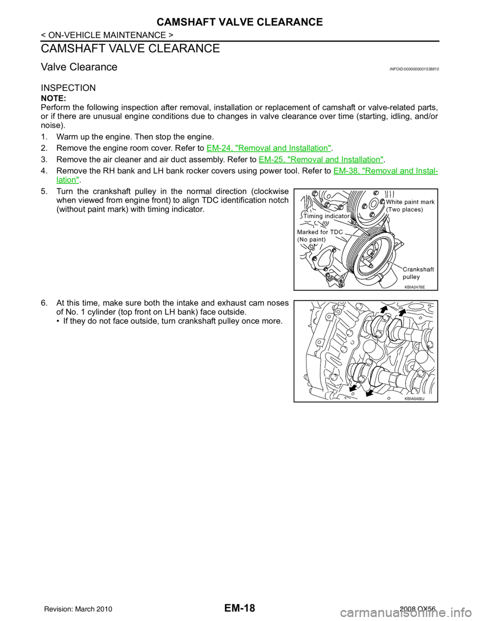
5. Turn the crankshaft pulley in the normal direction (clockwise when viewed from engine front) to align TDC identification notch
(without paint mark) with timing indicator.
6. At this time, make sure both the intake and exhaust cam noses of No. 1 cylinder (top front on LH bank) face outside.
• If they do not face outside, turn crankshaft pulley once more.
KBIA2476E
KBIA0400J
Revision: March 2010 2008 QX56
Page 1822 of 4083
CAMSHAFT VALVE CLEARANCEEM-19
< ON-VEHICLE MAINTENANCE >
C
DE
F
G H
I
J
K L
M A
EM
NP
O
7. Measure valve clearances at the locations marked “×
” as shown
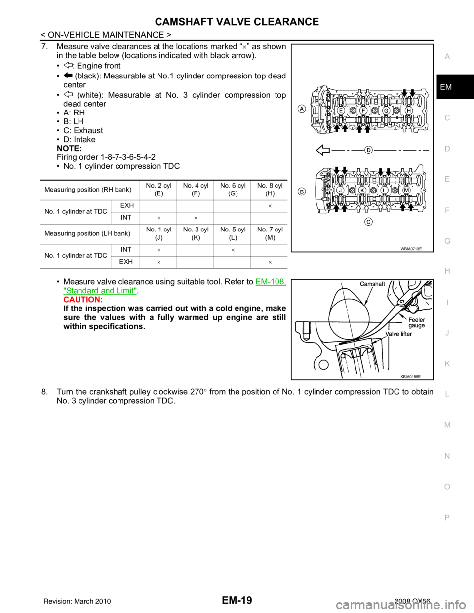
in the table below (locations indicated with black arrow).
• : Engine front
• (black): Measurable at No.1 cylinder compression top dead center
• (white): Measurable at No. 3 cylinder compression top dead center
•A: RH
•B: LH
• C: Exhaust
• D: Intake
NOTE:
Firing order 1-8-7-3-6-5-4-2
• No. 1 cylinder compression TDC
• Measure valve clearance using suitable tool. Refer to EM-108,
"Standard and Limit".
CAUTION:
If the inspection was carried out with a cold engine, make
sure the values with a fully warmed up engine are still
within specifications.
8. Turn the crankshaft pulley clockwise 270 ° from the position of No. 1 cylinder compression TDC to obtain
No. 3 cylinder compression TDC.
Measuring position (RH bank) No. 2 cyl
(E) No. 4 cyl
(F) No. 6 cyl
(G) No. 8 cyl
(H)
No. 1 cylinder at TDC EXH
×
INT ××
Measuring position (LH bank) No. 1 cyl
(J) No. 3 cyl
(K) No. 5 cyl
(L) No. 7 cyl
(M)
No. 1 cylinder at TDC INT
××
EXH ××
WBIA0713E
KBIA0185E
Revision: March 2010 2008 QX56
Page 1824 of 4083
CAMSHAFT VALVE CLEARANCEEM-21
< ON-VEHICLE MAINTENANCE >
C
DE
F
G H
I
J
K L
M A
EM
NP
O
10. Turn the crankshaft pulley clockwise 90°
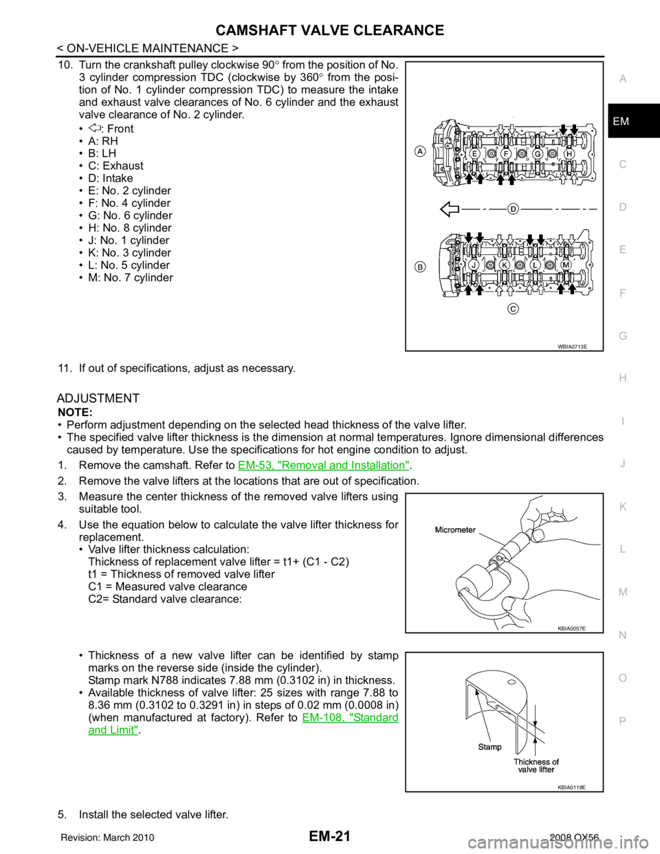
from the position of No.
3 cylinder compression TDC (clockwise by 360 ° from the posi-
tion of No. 1 cylinder compression TDC) to measure the intake
and exhaust valve clearances of No. 6 cylinder and the exhaust
valve clearance of No. 2 cylinder.
• : Front
•A: RH
•B: LH
• C: Exhaust
• D: Intake
• E: No. 2 cylinder
• F: No. 4 cylinder
• G: No. 6 cylinder
• H: No. 8 cylinder
• J: No. 1 cylinder
• K: No. 3 cylinder
• L: No. 5 cylinder
• M: No. 7 cylinder
11. If out of specifications, adjust as necessary.
ADJUSTMENT
NOTE:
• Perform adjustment depending on the selected head thickness of the valve lifter.
• The specified valve lifter thickness is the dimension at normal temperatures. Ignore dimensional differences
caused by temperature. Us e the specifications for hot engine condition to adjust.
1. Remove the camshaft. Refer to EM-53, "
Removal and Installation".
2. Remove the valve lifters at the locations that are out of specification.
3. Measure the center thickness of the removed valve lifters using suitable tool.
4. Use the equation below to calculate the valve lifter thickness for replacement.
• Valve lifter thickness calculation:Thickness of replacement valve lifter = t1+ (C1 - C2)
t1 = Thickness of removed valve lifter
C1 = Measured valve clearance
C2= Standard valve clearance:
• Thickness of a new valve lifter can be identified by stamp marks on the reverse side (inside the cylinder).
Stamp mark N788 indicates 7.88 mm (0.3102 in) in thickness.
• Available thickness of valve lifter: 25 sizes with range 7.88 to 8.36 mm (0.3102 to 0.3291 in) in steps of 0.02 mm (0.0008 in)
(when manufactured at factory). Refer to EM-108, "
Standard
and Limit".
5. Install the selected valve lifter.
WBIA0713E
KBIA0057E
KBIA0119E
Revision: March 2010 2008 QX56
Page 1849 of 4083

EM-46
< ON-VEHICLE REPAIR >
TIMING CHAIN
4. Obtain compression TDC of No. 1 cylinder as follows:
a. Turn the crankshaft pulley clockwise to align the TDC identifica-tion notch (without paint mark) with the timing indicator on the
front cover.
b. At this time, make sure both intake and exhaust cam lobes of No. 1 cylinder (top front on LH bank) point outside.
• If they do not point outside, turn crankshaft pulley once more.
5. Remove the crankshaft pulley.
a. Loosen the crankshaft pulley bolts using a hammer handle to secure the crankshaft.
b. Remove the crankshaft pulley from the crankshaft using tool. • Remove the crankshaft pulley using suitable tool. Set the boltsin the two bolt holes [M6 x 1.0 mm (0.04 in)] on the front sur-
face.
NOTE:
The dimension between the centers of the two bolt holes is 61
mm (2.40 in).
6. Remove the front cover.
a. Loosen and remove the bolts in the reverse of order shown.
b. Cut the liquid gasket and remove the covers using Tool. CAUTION:
Do not damage mating surfaces.
7. Remove the front oil seal using suitable tool. CAUTION:
Do not damage front cover.
KBIA2476E
KBIA0400J
PBIC0053E
KBIA2477E
Tool number : KV10111100 (J-37228)
KBIA2478E
Revision: March 2010 2008 QX56
Page 1855 of 4083
EM-52
< ON-VEHICLE REPAIR >
TIMING CHAIN
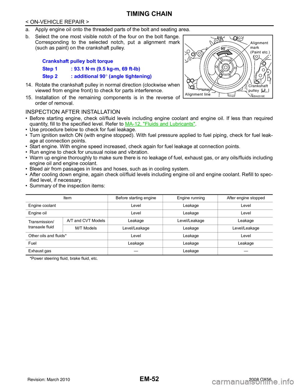
a. Apply engine oil onto the threaded parts of the bolt and seating area.
b. Select the one most visible notch of the four on the bolt flange.Corresponding to the selected notch, put a alignment mark
(such as paint) on the crankshaft pulley.
14. Rotate the crankshaft pulley in normal direction (clockwise when viewed from engine front) to check for parts interference.
15. Installation of the remaining components is in the reverse of order of removal.
INSPECTION AFTER INSTALLATION
• Before starting engine, check oil/fluid levels incl uding engine coolant and engine oil. If less than required
quantity, fill to the specified level. Refer to MA-12, "
Fluids and Lubricants".
• Use procedure below to check for fuel leakage.
• Turn ignition switch ON (with engine stopped). With fuel pressure applied to fuel piping, check for fuel leak- age at connection points.
• Start engine. With engine speed increased, che ck again for fuel leakage at connection points.
• Run engine to check for unusual noise and vibration.
• Warm up engine thoroughly to make sure there is no leakage of fuel, exhaust gas, or any oils/fluids including
engine oil and engine coolant.
• Bleed air from passages in lines and hoses, such as in cooling system.
• After cooling down engine, again check oil/fluid levels including engine oil and engine coolant. Refill to spec-
ified level, if necessary.
• Summary of the inspection items:
*Power steering fluid, brake fluid, etc.
Crankshaft pulley bolt torque
Step 1 : 93.1 N·m (9.5 kg-m, 69 ft-lb)
Step 2 : additional 90 ° (angle tightening)
KBIA2519E
Item Before starting engine Engine runningAfter engine stopped
Engine coolant LevelLeakage Level
Engine oil LevelLeakage Level
Transmission/
transaxle fluid A/T and CVT Models
LeakageLevel/Leakage Leakage
M/T Models Level/Leakage LeakageLevel/Leakage
Other oils and fluids* LevelLeakage Level
Fuel LeakageLeakage Leakage
Exhaust gas —Leakage —
Revision: March 2010 2008 QX56
Page 1857 of 4083

EM-54
< ON-VEHICLE REPAIR >
CAMSHAFT
2. Obtain compression TDC of No. 1 cylinder as follows:
a. Turn the crankshaft pulley clockwise to align the TDC identifica-tion notch (without paint mark) with the timing indicator on the
front cover.
b. At this time, make sure both intake and exhaust cam lobes of No. 1 cylinder (top front on LH bank) point outside.
• If they do not point outside, turn crankshaft pulley once more.
3. Remove the intake valve timing control solenoid cover RH bank (A) and intake valve timing control solenoid cover LH bank (B)
as follows:
a. Loosen and remove the bolts as shown.
b. Cut the liquid gasket and remove the covers using Tool.
CAUTION:
Do not damage mating surfaces.
4. Paint alignment marks on the RH bank (A) timing chain links (C) and LH bank (B) timing chain links (D) and align with the cam-
shaft sprocket alignment marks (E) and (F).
5. Remove the LH bank timing chain tensioner using the following steps. WARNING:
Plunger, spring, and spring seat pop out when squeezing return-proof clip without holding
plunger head. It may cause serious injuries. Always hold plunger head when removing.
KBIA2476E
KBIA0400J
Tool number : KV10111100 (J-37228)
WBIA0798E
AWBIA0154ZZ
Revision: March 2010 2008 QX56
Page 1872 of 4083
CYLINDER HEADEM-69
< ON-VEHICLE REPAIR >
C
DE
F
G H
I
J
K L
M A
EM
NP
O
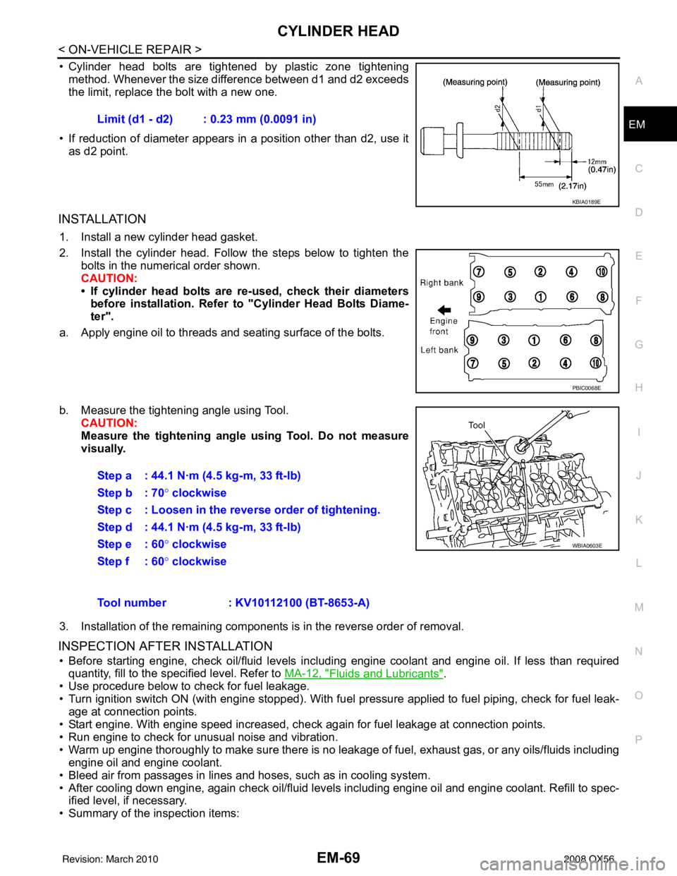
• Cylinder head bolts are tightened by plastic zone tightening
method. Whenever the size difference between d1 and d2 exceeds
the limit, replace the bolt with a new one.
• If reduction of diameter appears in a position other than d2, use it as d2 point.
INSTALLATION
1. Install a new cylinder head gasket.
2. Install the cylinder head. Follow the steps below to tighten the bolts in the numerical order shown.
CAUTION:
• If cylinder head bolts are re-used, check their diameters
before installation. Refer to "Cylinder Head Bolts Diame-
ter".
a. Apply engine oil to threads and seating surface of the bolts.
b. Measure the tightening angle using Tool. CAUTION:
Measure the tightening angl e using Tool. Do not measure
visually.
3. Installation of the remaining components is in the reverse order of removal.
INSPECTION AFTER INSTALLATION
• Before starting engine, check oil/fluid levels incl uding engine coolant and engine oil. If less than required
quantity, fill to the specified level. Refer to MA-12, "
Fluids and Lubricants".
• Use procedure below to check for fuel leakage.
• Turn ignition switch ON (with engine stopped). With fuel pressure applied to fuel piping, check for fuel leak-
age at connection points.
• Start engine. With engine speed increased, check again for fuel leakage at connection points.
• Run engine to check for unusual noise and vibration.
• Warm up engine thoroughly to make sure there is no leak age of fuel, exhaust gas, or any oils/fluids including
engine oil and engine coolant.
• Bleed air from passages in lines and hoses, such as in cooling system.
• After cooling down engine, again check oil/fluid levels including engine oil and engine coolant. Refill to spec- ified level, if necessary.
• Summary of the inspection items: Limit (d1 - d2) : 0.23 mm (0.0091 in)
KBIA0189E
PBIC0068E
Step a : 44.1 N·m (4.5 kg-m, 33 ft-lb)
Step b : 70°
clockwise
Step c : Loosen in the reverse order of tightening.
Step d : 44.1 N·m (4.5 kg-m, 33 ft-lb)
Step e : 60 ° clockwise
Step f : 60° clockwise
WBIA0603E
Tool number : KV10112100 (BT-8653-A)
Revision: March 2010 2008 QX56