INFINITI QX56 2008 Factory Service Manual
QX56 2008
INFINITI
INFINITI
https://www.carmanualsonline.info/img/42/57030/w960_57030-0.png
INFINITI QX56 2008 Factory Service Manual
Trending: fuel cap, wipers, wiring, wheel bolts, steering, service indicator, driver seat adjustment
Page 3811 of 4083
TM-264
< DISASSEMBLY AND ASSEMBLY >
REPAIR FOR COMPONENT PARTS
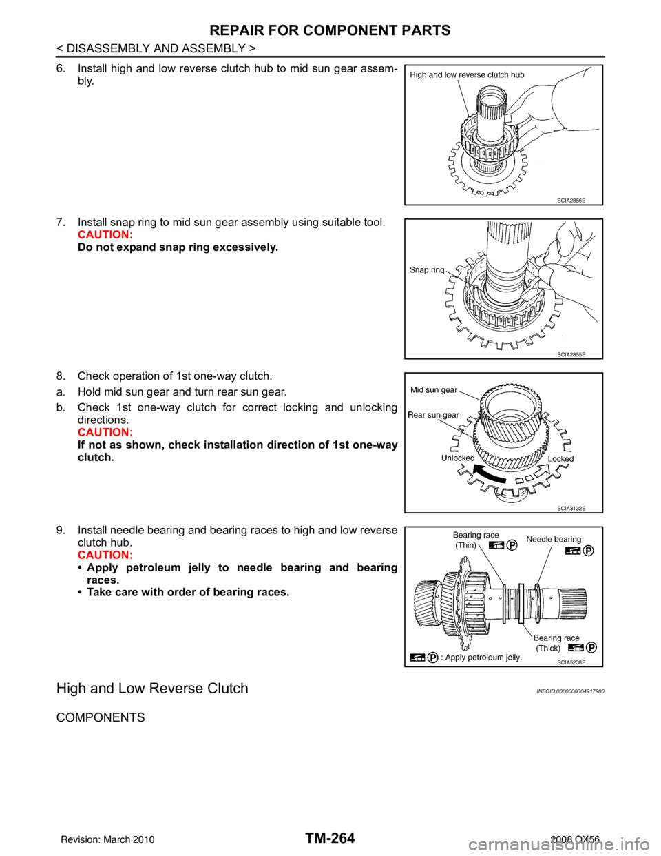
6. Install high and low reverse clutch hub to mid sun gear assem-bly.
7. Install snap ring to mid sun gear assembly using suitable tool. CAUTION:
Do not expand snap ring excessively.
8. Check operation of 1st one-way clutch.
a. Hold mid sun gear and turn rear sun gear.
b. Check 1st one-way clutch for correct locking and unlocking directions.
CAUTION:
If not as shown, check installa tion direction of 1st one-way
clutch.
9. Install needle bearing and bearing races to high and low reverse clutch hub.
CAUTION:
• Apply petroleum jelly to n eedle bearing and bearing
races.
• Take care with order of bearing races.
High and Low Reverse ClutchINFOID:0000000004917900
COMPONENTS
SCIA2856E
SCIA2855E
SCIA3132E
SCIA5238E
Revision: March 2010 2008 QX56
Page 3812 of 4083
REPAIR FOR COMPONENT PARTSTM-265
< DISASSEMBLY AND ASSEMBLY >
CEF
G H
I
J
K L
M A
B
TM
N
O P
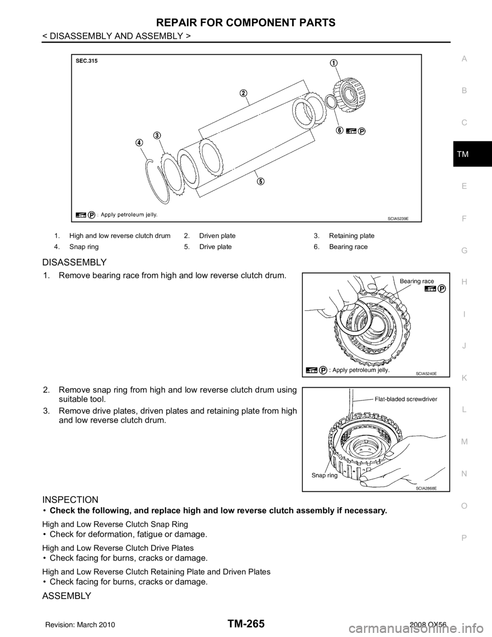
DISASSEMBLY
1. Remove bearing race from high and low reverse clutch drum.
2. Remove snap ring from high and low reverse clutch drum using suitable tool.
3. Remove drive plates, driven plates and retaining plate from high and low reverse clutch drum.
INSPECTION
•Check the following, and replace high an d low reverse clutch assembly if necessary.
High and Low Reverse Clutch Snap Ring
• Check for deformation, fatigue or damage.
High and Low Reverse Clutch Drive Plates
• Check facing for burns, cracks or damage.
High and Low Reverse Clutch Retaining Plate and Driven Plates
• Check facing for burns, cracks or damage.
ASSEMBLY
1. High and low reverse clutch drum 2. Driven plate 3. Retaining plate
4. Snap ring 5. Drive plate6. Bearing race
SCIA5239E
SCIA5240E
SCIA2868E
Revision: March 2010 2008 QX56
Page 3813 of 4083
TM-266
< DISASSEMBLY AND ASSEMBLY >
REPAIR FOR COMPONENT PARTS
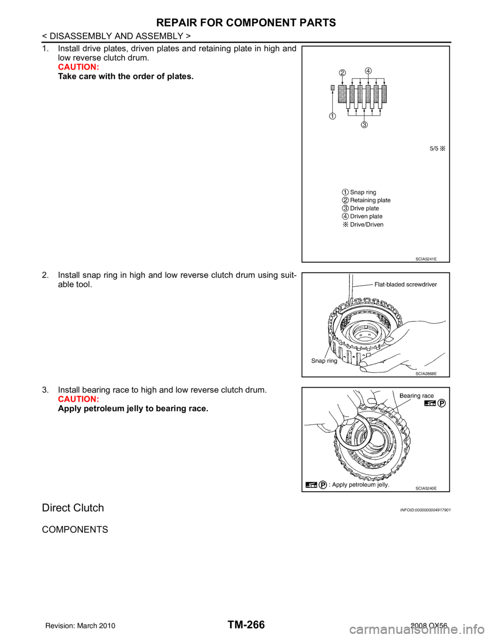
1. Install drive plates, driven plates and retaining plate in high andlow reverse clutch drum.
CAUTION:
Take care with the order of plates.
2. Install snap ring in high and low reverse clutch drum using suit- able tool.
3. Install bearing race to high and low reverse clutch drum. CAUTION:
Apply petroleum jelly to bearing race.
Direct ClutchINFOID:0000000004917901
COMPONENTS
SCIA5241E
SCIA2868E
SCIA5240E
Revision: March 2010 2008 QX56
Page 3814 of 4083
REPAIR FOR COMPONENT PARTSTM-267
< DISASSEMBLY AND ASSEMBLY >
CEF
G H
I
J
K L
M A
B
TM
N
O P
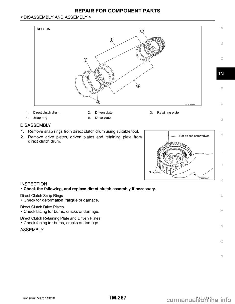
DISASSEMBLY
1. Remove snap rings from direct clutch drum using suitable tool.
2. Remove drive plates, driven plates and retaining plate from direct clutch drum.
INSPECTION
•Check the following, and replace di rect clutch assembly if necessary.
Direct Clutch Snap Rings
• Check for deformation, fatigue or damage.
Direct Clutch Drive Plates
• Check facing for burns, cracks or damage.
Direct Clutch Retaining Plate and Driven Plates
• Check facing for burns, cracks or damage.
ASSEMBLY
1. Direct clutch drum 2. Driven plate3. Retaining plate
4. Snap ring 5. Drive plate
SCIA5242E
SCIA2868E
Revision: March 2010 2008 QX56
Page 3815 of 4083
TM-268
< DISASSEMBLY AND ASSEMBLY >
REPAIR FOR COMPONENT PARTS
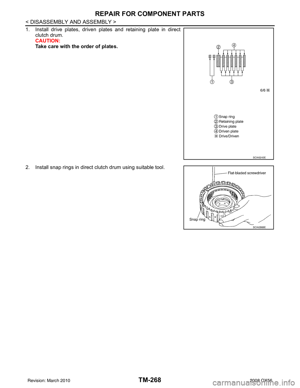
1. Install drive plates, driven plates and retaining plate in directclutch drum.
CAUTION:
Take care with the order of plates.
2. Install snap rings in direct clutch drum using suitable tool.
SCIA5243E
SCIA2868E
Revision: March 2010 2008 QX56
Page 3816 of 4083
ASSEMBLYTM-269
< DISASSEMBLY AND ASSEMBLY >
CEF
G H
I
J
K L
M A
B
TM
N
O P
ASSEMBLY
Assembly (1)INFOID:0000000004917902
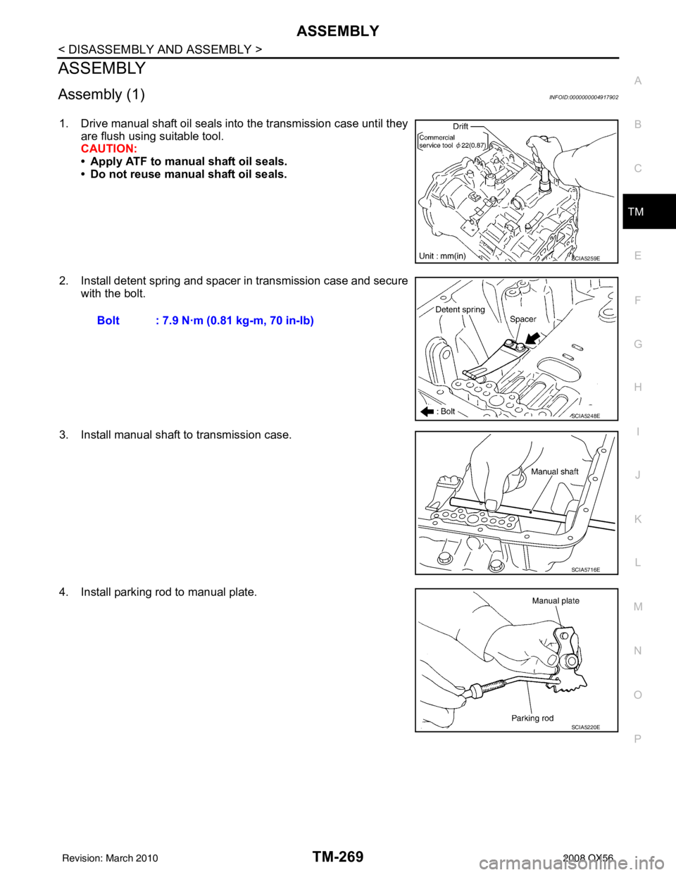
1. Drive manual shaft oil seals into the transmission case until they are flush using suitable tool.
CAUTION:
• Apply ATF to manual shaft oil seals.
• Do not reuse manual shaft oil seals.
2. Install detent spring and spacer in transmission case and secure with the bolt.
3. Install manual shaft to transmission case.
4. Install parking rod to manual plate.
SCIA5259E
Bolt : 7.9 N·m (0.81 kg-m, 70 in-lb)
SCIA5248E
SCIA5716E
SCIA5220E
Revision: March 2010 2008 QX56
Page 3817 of 4083
TM-270
< DISASSEMBLY AND ASSEMBLY >
ASSEMBLY
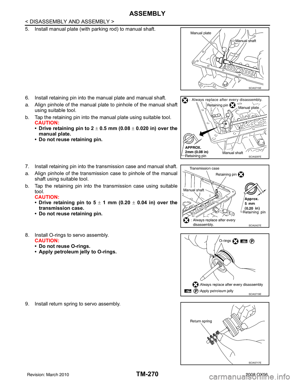
5. Install manual plate (with parking rod) to manual shaft.
6. Install retaining pin into the manual plate and manual shaft.
a. Align pinhole of the manual plate to pinhole of the manual shaftusing suitable tool.
b. Tap the retaining pin into the manual plate using suitable tool. CAUTION:
• Drive retaining pin to 2 ± 0.5 mm (0.08 ± 0.020 in) over the
manual plate.
• Do not reuse retaining pin.
7. Install retaining pin into the transmission case and manual shaft.
a. Align pinhole of the transmission case to pinhole of the manual shaft using suitable tool.
b. Tap the retaining pin into the transmission case using suitable tool.
CAUTION:
• Drive retaining pin to 5 ± 1 mm (0.20 ± 0.04 in) over the
transmission case.
• Do not reuse retaining pin.
8. Install O-rings to servo assembly. CAUTION:
• Do not reuse O-rings.
• Apply petroleum jelly to O-rings.
9. Install return spring to servo assembly.
SCIA5715E
SCIA5297E
SCIA2427E
SCIA5719E
SCIA5717E
Revision: March 2010 2008 QX56
Page 3818 of 4083
ASSEMBLYTM-271
< DISASSEMBLY AND ASSEMBLY >
CEF
G H
I
J
K L
M A
B
TM
N
O P
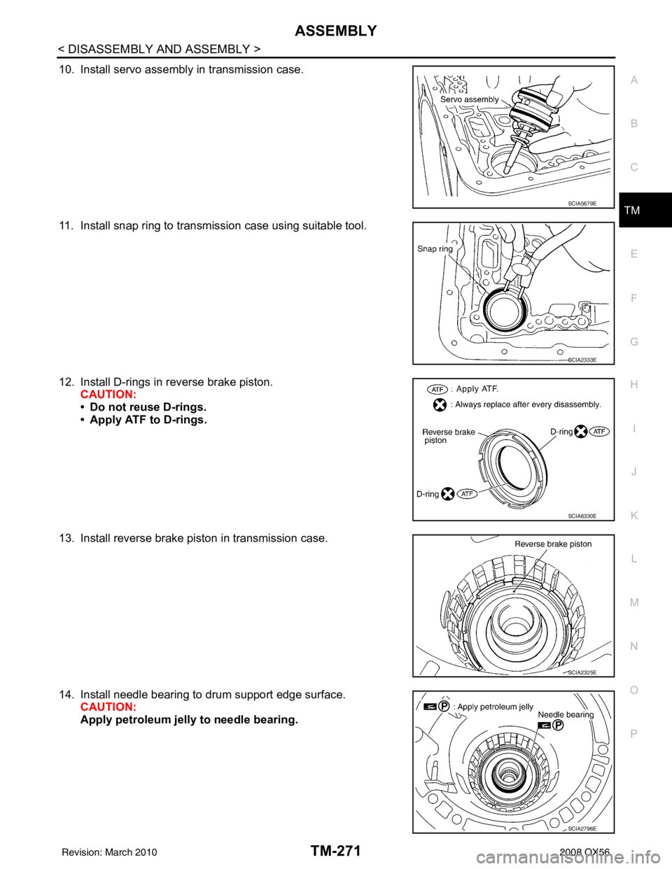
10. Install servo assembly in transmission case.
11. Install snap ring to transmission case using suitable tool.
12. Install D-rings in reverse brake piston. CAUTION:
• Do not reuse D-rings.
• Apply ATF to D-rings.
13. Install reverse brake piston in transmission case.
14. Install needle bearing to drum support edge surface. CAUTION:
Apply petroleum jelly to needle bearing.
SCIA5679E
SCIA2333E
SCIA6330E
SCIA2325E
SCIA2796E
Revision: March 2010 2008 QX56
Page 3819 of 4083
TM-272
< DISASSEMBLY AND ASSEMBLY >
ASSEMBLY
15. Install seal rings to drum support.CAUTION:
• Do not reuse seal rings.
• Apply petroleum jelly to seal rings.
16. Install spring retainer and return spring in transmission case.
17. Install snap ring in transmission case while compressing return spring using Tool.
CAUTION:
Securely assemble them using a flat-bladed screwdriver so
that snap ring tension is slightly weak.
18. Install reversr brake drive plates driven plates and dish plates in transmission case. CAUTION:
SCIA3333E
SCIA2324E
Tool number : KV31102400 (J-34285 and J-34285-87)
SCIA5877E
Revision: March 2010 2008 QX56
Page 3820 of 4083
ASSEMBLYTM-273
< DISASSEMBLY AND ASSEMBLY >
CEF
G H
I
J
K L
M A
B
TM
N
O P
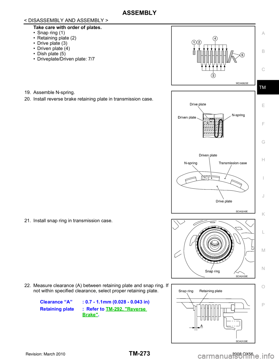
Take care with order of plates.
• Snap ring (1)
• Retaining plate (2)
• Drive plate (3)
• Driven plate (4)
• Dish plate (5)
• Driveplate/Driven plate: 7/7
19. Assemble N-spring.
20. Install reverse brake retaining plate in transmission case.
21. Install snap ring in transmission case.
22. Measure clearance (A) between retaining plate and snap ring. If not within specified clearance, select proper retaining plate.
WCIA0625E
SCIA5249E
SCIA2439E
Clearance “A” : 0.7 - 1.1mm (0.028 - 0.043 in)
Retaining plate : Refer to TM-292, "
Reverse
Brake".
SCIA3129E
Revision: March 2010 2008 QX56
Trending: air bleeding, rear entertainment, cabin filter, electronic brake force distribution, fold seats, fuse chart, wipers
