glass INFINITI QX56 2008 Factory Service Manual
[x] Cancel search | Manufacturer: INFINITI, Model Year: 2008, Model line: QX56, Model: INFINITI QX56 2008Pages: 4083, PDF Size: 81.73 MB
Page 1 of 4083
A
B
C
D
E
F
G
H
I
J
K
L
M
N
P
O
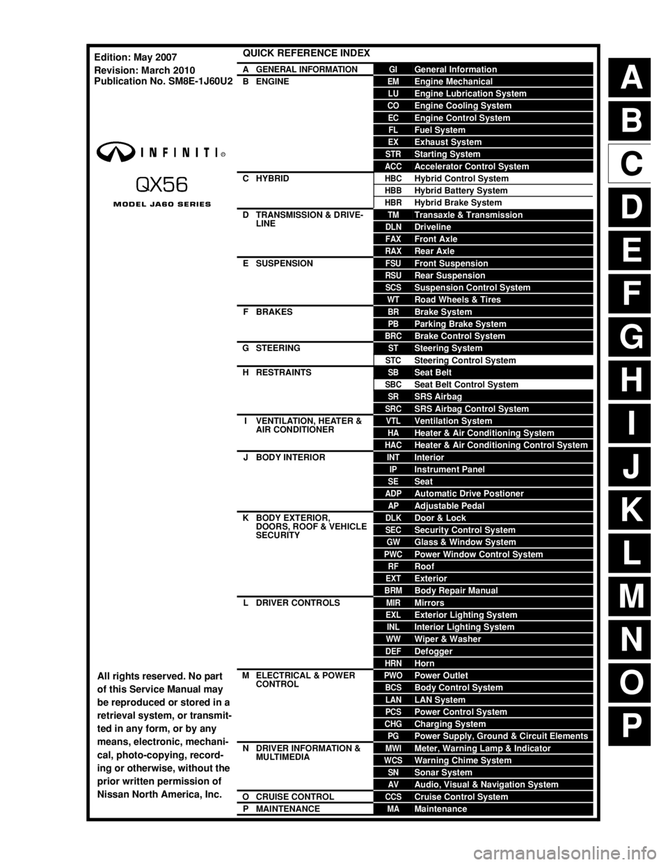
QUICK REFERENCE INDEX
AGENERAL INFORMATIONGIGeneral Information
BENGINEEMEngine Mechanical
LUEngine Lubrication System
COEngine Cooling System
ECEngine Control System
FLFuel System
EXExhaust System
STRStarting System
ACCAccelerator Control System
CHYBRIDHBCHybrid Control System
HBBHybrid Battery System
HBRHybrid Brake System
DTRANSMISSION & DRIVE-
LINETMTransaxle & Transmission
DLNDriveline
FAXFront Axle
RAXRear Axle
ESUSPENSIONFSUFront Suspension
RSURear Suspension
SCSSuspension Control System
WTRoad Wheels & Tires
FBRAKESBRBrake System
PBParking Brake System
BRCBrake Control System
GSTEERINGSTSteering System
STCSteering Control System
HRESTRAINTSSBSeat Belt
SBCSeat Belt Control System
SRSRS Airbag
SRCSRS Airbag Control System
IVENTILATION, HEATER &
AIR CONDITIONERVTLVentilation System
HAHeater & Air Conditioning System
HACHeater & Air Conditioning Control System
JBODY INTERIORINTInterior
IPInstrument Panel
SESeat
ADPAutomatic Drive Postioner
APAdjustable Pedal
KBODY EXTERIOR,
DOORS, ROOF & VEHICLE
SECURITYDLKDoor & Lock
SECSecurity Control System
GWGlass & Window System
PWCPower Window Control System
RFRoof
EXTExterior
BRMBody Repair Manual
LDRIVER CONTROLSMIRMirrors
EXLExterior Lighting System
INLInterior Lighting System
WWWiper & Washer
DEFDefogger
HRNHorn
MELECTRICAL & POWER
CONTROLPWOPower Outlet
BCSBody Control System
LANLAN System
PCSPower Control System
CHGCharging System
PGPower Supply, Ground & Circuit Elements
NDRIVER INFORMATION &
MULTIMEDIAMWIMeter, Warning Lamp & Indicator
WCSWarning Chime System
SNSonar System
AVAudio, Visual & Navigation System
OCRUISE CONTROLCCSCruise Control System
PMAINTENANCEMAMaintenance
All rights reserved. No part
of this Service Manual may
be reproduced or stored in a
retrieval system, or transmit-
ted in any form, or by any
means, electronic, mechani-
cal, photo-copying, record-
ing or otherwise, without the
prior written permission of
Nissan North America, Inc.
Edition: May 2007
Revision: March 2010
Publication No. SM8E-1J60U2
Page 160 of 4083
ADP-146
< ECU DIAGNOSIS >
BCM (BODY CONTROL MODULE)
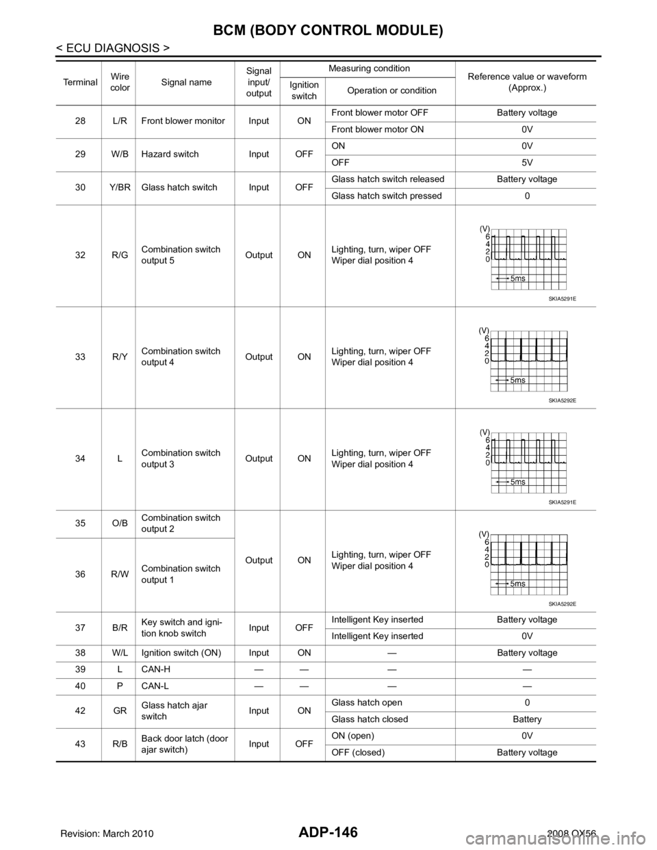
28 L/R Front blower monitor Input ONFront blower motor OFF
Battery voltage
Front blower motor ON 0V
29 W/B Hazard switch Input OFFON
0V
OFF 5V
30 Y/BR Glass hatch switch Input OFF Glass hatch switch released
Battery voltage
Glass hatch switch pressed 0
32 R/G Combination switch
output 5
Output ONLighting, turn, wiper OFF
Wiper dial position 4
33 R/Y Combination switch
output 4 Output ONLighting, turn, wiper OFF
Wiper dial position 4
34 L Combination switch
output 3 Output ON
Lighting, turn, wiper OFF
Wiper dial position 4
35 O/B Combination switch
output 2
Output ONLighting, turn, wiper OFF
Wiper dial position 4
36 R/W Combination switch
output 1
37 B/R Key switch and igni-
tion knob switch Input OFFIntelligent Key inserted
Battery voltage
Intelligent Key inserted 0V
38 W/L Ignition switch (ON) Input ON —Battery voltage
39 L CAN-H — —— —
40 P CAN-L — —— —
42 GR Glass hatch ajar
switch Input ONGlass hatch open
0
Glass hatch closed Battery
43 R/B Back door latch (door
ajar switch) Input OFFON (open)
0V
OFF (closed) Battery voltage
Te r m i n a l
Wire
color Signal name Signal
input/
output Measuring condition
Reference value or waveform
(Approx.)
Ignition
switch Operation or condition
SKIA5291E
SKIA5292E
SKIA5291E
SKIA5292E
Revision: March 2010
2008 QX56
Page 161 of 4083
BCM (BODY CONTROL MODULE)ADP-147
< ECU DIAGNOSIS >
C
DE
F
G H
I
K L
M A
B
ADP
N
O P
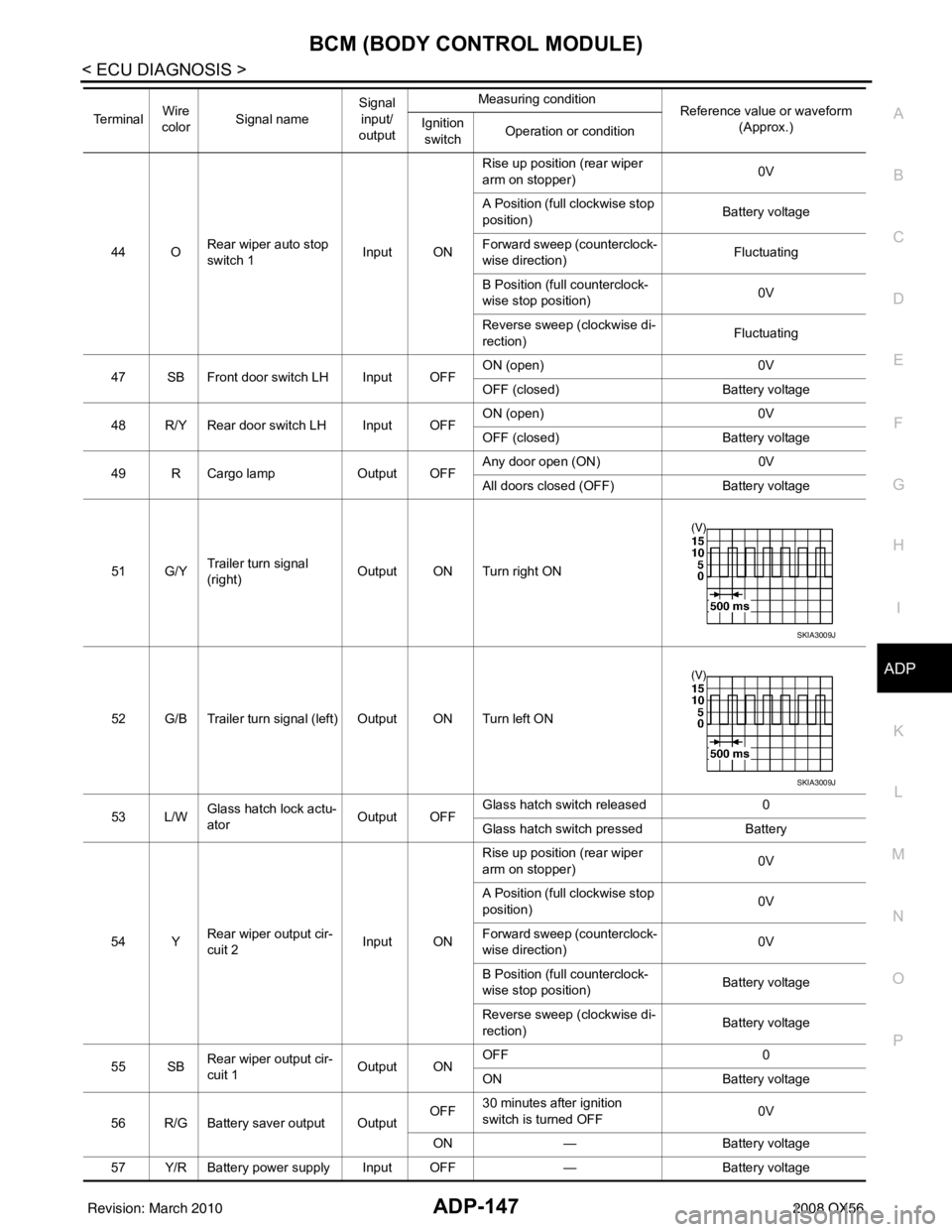
44 O Rear wiper auto stop
switch 1 Input ONRise up position (rear wiper
arm on stopper)
0V
A Position (full clockwise stop
position) Battery voltage
Forward sweep (counterclock-
wise direction) Fluctuating
B Position (full counterclock-
wise stop position) 0V
Reverse sweep (clockwise di-
rection) Fluctuating
47 SB Front door switch LH Input OFF ON (open)
0V
OFF (closed) Battery voltage
48 R/Y Rear door switch LH Input OFF ON (open)
0V
OFF (closed) Battery voltage
49 R Cargo lamp Output OFFAny door open (ON)
0V
All doors closed (OFF) Battery voltage
51 G/Y Trailer turn signal
(right) Output ON Turn right ON
52 G/B Trailer turn signal (left) Output ON Turn left ON
53 L/W Glass hatch lock actu-
ator
Output OFFGlass hatch switch released
0
Glass hatch switch pressed Battery
54 Y Rear wiper output cir-
cuit 2 Input ONRise up position (rear wiper
arm on stopper)
0V
A Position (full clockwise stop
position) 0V
Forward sweep (counterclock-
wise direction) 0V
B Position (full counterclock-
wise stop position) Battery voltage
Reverse sweep (clockwise di-
rection) Battery voltage
55 SB Rear wiper output cir-
cuit 1 Output ONOFF
0
ON Battery voltage
56 R/G Battery saver output Output OFF
30 minutes after ignition
switch is turned OFF 0V
ON — Battery voltage
57 Y/R Battery power supply Input OFF —Battery voltage
Te r m i n a l
Wire
color Signal name Signal
input/
output Measuring condition
Reference value or waveform
(Approx.)
Ignition
switch Operation or condition
SKIA3009J
SKIA3009J
Revision: March 2010
2008 QX56
Page 408 of 4083
![INFINITI QX56 2008 Factory Service Manual BCS
BCM (BODY CONTROL MODULE)BCS-43
< ECU DIAGNOSIS > [BCM]
C
D
E
F
G H
I
J
K L
B A
O P
N
28 L/R Front blower monitor Input ON
Front blower motor OFF Battery voltage
Front blower motor ON
0V
29 W/B Ha](/img/42/57030/w960_57030-407.png "INFINITI QX56 2008 Factory Service Manual BCS
BCM (BODY CONTROL MODULE)BCS-43
< ECU DIAGNOSIS > [BCM]
C
D
E
F
G H
I
J
K L
B A
O P
N
28 L/R Front blower monitor Input ON
Front blower motor OFF Battery voltage
Front blower motor ON
0V
29 W/B Ha")
BCS
BCM (BODY CONTROL MODULE)BCS-43
< ECU DIAGNOSIS > [BCM]
C
D
E
F
G H
I
J
K L
B A
O P
N
28 L/R Front blower monitor Input ON
Front blower motor OFF Battery voltage
Front blower motor ON
0V
29 W/B Hazard switch Input OFFON
0V
OFF 5V
30 Y/BR Glass hatch switch Input OFF Glass hatch switch released
Battery voltage
Glass hatch switch pressed 0
32 R/G Combination switch
output 5
Output ONLighting, turn, wiper OFF
Wiper dial position 4
33 R/Y Combination switch
output 4 Output ONLighting, turn, wiper OFF
Wiper dial position 4
34 L Combination switch
output 3 Output ON
Lighting, turn, wiper OFF
Wiper dial position 4
35 O/B Combination switch
output 2
Output ONLighting, turn, wiper OFF
Wiper dial position 4
36 R/W Combination switch
output 1
37 B/R Key switch and igni-
tion knob switch Input OFFIntelligent Key inserted
Battery voltage
Intelligent Key inserted 0V
38 W/L Ignition switch (ON) Input ON —Battery voltage
39 L CAN-H — —— —
40 P CAN-L — —— —
42 GR Glass hatch ajar
switch Input ONGlass hatch open
0
Glass hatch closed Battery
43 R/B Back door latch (door
ajar switch) Input OFFON (open)
0V
OFF (closed) Battery voltage
Te r m i n a l
Wire
color Signal name Signal
input/
output Measuring condition
Reference value or waveform
(Approx.)
Ignition
switch Operation or condition
SKIA5291E
SKIA5292E
SKIA5291E
SKIA5292E
Revision: March 2010
2008 QX56
Page 409 of 4083
![INFINITI QX56 2008 Factory Service Manual BCS-44
< ECU DIAGNOSIS >[BCM]
BCM (BODY CONTROL MODULE)
44 ORear wiper auto stop
switch 1 Input ONRise up position (rear wiper
arm on stopper)
0V
A Position (full clockwise stop
position) Battery v](/img/42/57030/w960_57030-408.png "INFINITI QX56 2008 Factory Service Manual BCS-44
< ECU DIAGNOSIS >[BCM]
BCM (BODY CONTROL MODULE)
44 ORear wiper auto stop
switch 1 Input ONRise up position (rear wiper
arm on stopper)
0V
A Position (full clockwise stop
position) Battery v")
BCS-44
< ECU DIAGNOSIS >[BCM]
BCM (BODY CONTROL MODULE)
44 ORear wiper auto stop
switch 1 Input ONRise up position (rear wiper
arm on stopper)
0V
A Position (full clockwise stop
position) Battery voltage
Forward sweep (counterclock-
wise direction) Fluctuating
B Position (full counterclock-
wise stop position) 0V
Reverse sweep (clockwise di-
rection) Fluctuating
47 SB Front door switch LH Input OFF ON (open)
0V
OFF (closed) Battery voltage
48 R/Y Rear door switch LH Input OFF ON (open)
0V
OFF (closed) Battery voltage
49 R Cargo lamp Output OFFAny door open (ON)
0V
All doors closed (OFF) Battery voltage
51 G/Y Trailer turn signal
(right) Output ON Turn right ON
52 G/B Trailer turn signal (l eft) Output ON Turn left ON
53 L/W Glass hatch lock actu-
ator
Output OFFGlass hatch switch released
0
Glass hatch switch pressed Battery
54 Y Rear wiper output cir-
cuit 2 Input ONRise up position (rear wiper
arm on stopper)
0V
A Position (full clockwise stop
position) 0V
Forward sweep (counterclock-
wise direction) 0V
B Position (full counterclock-
wise stop position) Battery voltage
Reverse sweep (clockwise di-
rection) Battery voltage
55 SB Rear wiper output cir-
cuit 1 Output ONOFF
0
ON Battery voltage
56 R/G Battery saver output Output OFF
30 minutes after ignition
switch is turned OFF 0V
ON — Battery voltage
57 Y/R Battery power supply Input OFF —Battery voltage
Te r m i n a l
Wire
color Signal name Signal
input/
output Measuring condition
Reference value or waveform
(Approx.)
Ignition
switch Operation or condition
SKIA3009J
SKIA3009J
Revision: March 2010
2008 QX56
Page 681 of 4083

CCS
DTC 102 LASER STAINCCS-41
< COMPONENT DIAGNOSIS >
C
DE
F
G H
I
J
K L
M B
N P A
DTC 102 LASER STAIN
DTC 102 LASER STAININFOID:0000000001744716
1.VISUAL INSPECTION (1)
Check that there is no cont amination and foreign material on ICC sensor body window.
Is the ICC sensor clean?
YES >> GO TO 2
NO >> • Clean ICC sensor. • Erase DTC and perform ICC system running test. Refer to CCS-8, "
ACTION TEST : ICC Sys-
tem Running Test".
2.VISUAL INSPECTION (2)
Check ICC sensor body window for cracks.
Is the ICC sensor window undamaged?
YES >> GO TO 3
NO >> • Replace ICC sensor and adjust laser beam. Refer to CCS-71, "
ICC Sensor".
• Erase DTC and perform ICC system running test. Refer to CCS-8, "
ACTION TEST : ICC Sys-
tem Running Test".
3.ASK CUSTOMER FOR DRIVING CONDITIONS
1. Is there any trace of contamination or foreign material on ICC sensor?
2. Is there any possibility that vehicle was driven in snow or ICC sensor was frosted?
3. Is there any possibility that ICC sensor was fogged temporarily? (Front window glass may have also been fogged.)
Was the ICC sensor obstructed by normal conditions?
YES >> Explain system operation and parameters to customer. System may be operating normally.
NO >> • Replace ICC sensor and adjust laser beam aiming. Refer to CCS-71, "
ICC Sensor".
• Erase DTC and perform ICC system running test. Refer to CCS-8, "
ACTION TEST : ICC Sys-
tem Running Test".
Revision: March 2010 2008 QX56
Page 793 of 4083

DEF-34
< ON-VEHICLE REPAIR >
REAR WINDOW DEFOGGER
• Drawing pen
• Heat gun
• Alcohol
• Cloth
REPAIRING PROCEDURE
1. Wipe broken heat wire and its surrounding area clean with acloth dampened in alcohol.
2. Apply a small amount of conductive silver composition to tip of drawing pen.
Shake silver composition container before use.
3. Place ruler on glass along broken line. Deposit conductive silver composition on break with drawing pen. Slightly overlap existing
heat wire on both sides [preferably 5 mm (0.20 in)] of the break.
4. After repair has been completed, check repaired wire for conti- nuity. This check should be conducted 10 minutes after silver
composition is deposited.
Do not touch repaired area while test is being conducted.
5. Apply a constant stream of hot air directly to the repaired area for approximately 20 minutes with a heat gun. A minimum dis-
tance of 3 cm (1.2 in) should be kept between repaired area and
hot air outlet.
If a heat gun is not available, let the repaired area dry for 24
hours.
PIIA0215E
SEL012D
SEL013D
Revision: March 2010 2008 QX56
Page 796 of 4083

DLK-3
C
DE
F
G H
I
J
L
M A
B
DLK
N
O P
REAR LH : Diagnosis Procedure ........................
....
84
REAR RH ............................................................... ....85
REAR RH : Description ...........................................85
REAR RH : Component Function Check ...............86
REAR RH : Diagnosis Procedure ............................86
BACK DOOR ......................................................... ....87
BACK DOOR : Description ......................................87
GLASS HATCH LOCK ACTUATOR ..................88
Diagnosis Procedure ...............................................88
PASSENGER SELECT UNLOCK RELAY .........89
Description .......................................................... ....89
Component Function Check ....................................89
Diagnosis Procedure ...............................................89
INTELLIGENT KEY WARNING BUZZER ..........91
Description .......................................................... ....91
Component Function Check ..................................91
Diagnosis Procedure ...............................................91
Component Inspection ............................................92
OUTSIDE KEY ANTENNA .................................93
Description .......................................................... ....93
Component Function Check ..................................93
Diagnosis Procedure ...............................................93
STEERING LOCK UNIT .....................................95
Diagnosis Procedure ........................................... ....95
A/T SHIFT SELECTOR (PARK POSITION
SWITCH) .............................................................
97
Diagnosis Procedure ........................................... ....97
REMOTE KEYLESS ENTRY RECEIVER ..........99
Description .......................................................... ....99
Component Function Check ..................................99
Diagnosis Procedure ...............................................99
INTELLIGENT KEY BATTERY AND FUNC-
TION .................................................................
102
Description .......................................................... ..102
Component Function Check ................................102
Diagnosis Procedure .............................................102
Component Inspection ..........................................102
Special Repair Requirement .................................103
HORN FUNCTION .......................................... ..104
Description .......................................................... ..104
Component Function Check ................................104
Diagnosis Procedure ............................................104
COMBINATION METER DISPLAY FUNC-
TION .................................................................
106
Description .......................................................... ..106
Component Function Check ................................106
Diagnosis Procedure .............................................106
WARNING CHIME FUNCTION ........................107
Description .......................................................... ..107
Component Function Check .............................. ..107
Diagnosis Procedure .............................................107
HAZARD FUNCTION ......................................108
Description .............................................................108
Component Function Check ................................108
Diagnosis Procedure .............................................108
KEY SWITCH (INTELLIGENT KEY UNIT IN-
PUT) ................................................................
109
Diagnosis Procedure .............................................109
KEY SWITCH (BCM INPUT) ...........................111
Diagnosis Procedure .............................................111
IGNITION KNOB SWITCH ..............................112
Ignition Knob Switch Check ...................................112
HEADLAMP FUNCTION .................................114
Diagnosis Procedure .............................................114
MAP LAMP AND IGNITION KEYHOLE ILLU-
MINATION FUNCTION ...................................
115
Diagnosis Procedure .............................................115
KEYFOB ID SET UP WITH CONSULT-III ......116
ID Code Entry Procedure ......................................116
KEYFOB ID SET UP WITHOUT CONSULT-III .117
ID Code Entry Procedure .................................... ..117
AUTOMATIC BACK DOOR SELF-DIAGNO-
SIS PROCEDURE ...........................................
119
Self-Diagnosis Procedure ......................................119
POWER LIFTGATE SWITCH FUNCTION ......121
Diagnosis Procedure ........................................... ..121
GLASS HATCH SWITCH ................................123
Diagnosis Procedure .............................................123
GLASS HATCH AJAR SWITCH .....................125
Diagnosis Procedure .............................................125
BACK DOOR CLOSE (CLOSE) SWITCH
SYSTEM ..........................................................
127
Diagnosis Procedure ........................................... ..127
BACK DOOR CLOSE (CANCEL) SWITCH
SYSTEM ..........................................................
128
Diagnosis Procedure ........................................... ..128
PINCH STRIP SYSTEM ..................................129
Diagnosis Procedure .............................................129
BACK DOOR WARNING CHIME SYSTEM ....130
Diagnosis Procedure .............................................130
HALF-LATCH SWITCH SYSTEM ...................131
Diagnosis Procedure .............................................131
BACK DOOR OPEN SWITCH SYSTEM ........132
Diagnosis Procedure .............................................132
Revision: March 2010 2008 QX56
Page 804 of 4083
![INFINITI QX56 2008 Factory Service Manual DOOR LOCK FUNCTIONDLK-11
< FUNCTION DIAGNOSIS > [WITH INTELLIGENT KEY SYSTEM]
C
D
E
F
G H
I
J
L
M A
B
DLK
N
O P
DOOR LOCK AND UNLOCK SWITCH : Component Parts LocationINFOID:0000000001538908
DOOR LOCK](/img/42/57030/w960_57030-803.png "INFINITI QX56 2008 Factory Service Manual DOOR LOCK FUNCTIONDLK-11
< FUNCTION DIAGNOSIS > [WITH INTELLIGENT KEY SYSTEM]
C
D
E
F
G H
I
J
L
M A
B
DLK
N
O P
DOOR LOCK AND UNLOCK SWITCH : Component Parts LocationINFOID:0000000001538908
DOOR LOCK")
DOOR LOCK FUNCTIONDLK-11
< FUNCTION DIAGNOSIS > [WITH INTELLIGENT KEY SYSTEM]
C
D
E
F
G H
I
J
L
M A
B
DLK
N
O P
DOOR LOCK AND UNLOCK SWITCH : Component Parts LocationINFOID:0000000001538908
DOOR LOCK AND UNLOCK SWITCH : Component DescriptionINFOID:0000000001538909
1. Key switch and ignition knob switch M12 2. BCM M18, M19, M20 (view with instrument panel removed)3. Front door lock assembly LH (key
cylinder switch) D14
Front door lock actuator RH D114
4. Main power window and door lock/un- lock switch D7, D8 5. Front door switch
LH B8
RH B108 6. Rear door switch
LH B18
RH B116
7. Power window and door lock/unlock switch RH D105 8. Back door latch (door ajar switch)
D503 9. Rear door lock actuator
LH D205
RH D305
10. Passenger select unlock relay M7 (view with instrument panel LH removed) 11. Glass hatch lock actuator D711 12. Glass hatch switch D706
ALKIA0964ZZ
Item
Function
BCM Controls the door lock function and room lamp function.
Door lock and unlock switch Transmits lock or unlock signal to BCM.
Door lock actuator Receives lock/unlock signal from BCM and locks/unlocks each door.
Revision: March 2010 2008 QX56
Page 817 of 4083
![INFINITI QX56 2008 Factory Service Manual DLK-24
< FUNCTION DIAGNOSIS >[WITH INTELLIGENT KEY SYSTEM]
BACK DOOR OPENER FUNCTION
Power Liftgate Switch O
peration (Fully Closed → Fully Open Operation)
• When the power liftgate switch is pres](/img/42/57030/w960_57030-816.png "INFINITI QX56 2008 Factory Service Manual DLK-24
< FUNCTION DIAGNOSIS >[WITH INTELLIGENT KEY SYSTEM]
BACK DOOR OPENER FUNCTION
Power Liftgate Switch O
peration (Fully Closed → Fully Open Operation)
• When the power liftgate switch is pres")
DLK-24
< FUNCTION DIAGNOSIS >[WITH INTELLIGENT KEY SYSTEM]
BACK DOOR OPENER FUNCTION
Power Liftgate Switch O
peration (Fully Closed → Fully Open Operation)
• When the power liftgate switch is pressed, back door control unit terminal 23 receives the signal.
• The back door control unit checks the A/T shift selector lever (P) position through terminal 18, vehicle speed
through terminal 21, ignition status through terminal 7, glass hatch is closed through terminal 17 and battery
voltage is present through terminal 3.
• When the back door control unit receives the signal, if the auto back door operating enable conditions are
met, it sends a 5 volt signal through terminal 6 and grounds terminal 9 to sound the warning chime, sends a
signal to the BCM through terminal 4 to flash the hazard lamps and unlocks the back door latch through ter-
minal 12.
• The back door control unit supplies power to the magnetic clutch and the back door motor and moves the back door in the open direction. (At this time, it also executes speed control, input reverse, and anti-pinch
detection control.)
• When the back door is opened to the full-open position, the full-open position is detected by the encoder, and the back door control unit switches the back door motor OFF and the magnetic clutch is pulsed and then
turned OFF.
• The back door is held in the fully open position by the gas stays.
Remote Keyless Entry Operation (Fully Closed → Fully Open Operation)
• When the keyfob button is pressed for at least 0.5 seconds, back door control unit terminal 21 receives the
signal.
• The back door control unit checks the A/T shift selector lever (P) position through terminal 18, vehicle speed through terminal 21, ignition status through terminal 7, glass hatch is closed through terminal 17 and battery
voltage is present through terminal 3.
• When the back door control unit receives the signal, if the auto back door operating enable conditions are
met, it sends a 5 volt signal through terminal 6 and grounds terminal 9 to sound the warning chime, sends a
signal to the BCM through terminal 4 to flash the hazard lamps and unlocks the back door latch through ter-
minal 12.
• The back door control unit supplies power to the magnetic clutch and the back door motor and moves the
back door in the open direction. (At this time, it also executes speed control, input reverse, and anti-pinch
detection control.)
• When the back door is opened to the full-open position, the full-open position is detected by the encoder,
and the back door control unit switches the back door motor OFF and the magnetic clutch is pulsed and then
turned OFF.
• The back door is held in the fully open position by the gas stays.
Back Door Handle Switch Operation (Fully Closed → Fully Open Operation)
• When the back door handle is pulled, back door control unit terminal 26 receives the signal.
• The back door control unit checks that the back door is unlocked and checks the A/T shift selector lever (P)
position through terminal 18, vehicle speed through terminal 21, ignition status through terminal 7, glass
hatch is closed, battery voltage and back door close switch position through terminal 13.
• When the back door control unit receives the signal, if all auto back door operating enable conditions are
met, it sends a 5 volt signal through terminal 6 and grounds terminal 9 to sound the warning chime, sends a
signal to the BCM through terminal 4 to flash the hazard lamps and unlocks the back door latch through ter-
minal 12.
• The back door control unit supplies power to the magnetic clutch and the back door motor and moves the
back door in the open direction. (At this time, it also executes speed control, input reverse, and anti-pinch
detection control.)
• When the back door is opened to the full-open position, the full-open position is detected by the encoder,
and the back door control unit switches the back door motor OFF and the magnetic clutch is pulsed and then
turned OFF.
• The back door is held in the fully open position by the gas stays.
Power Liftgate Switch Operation (Fully Open → Fully Closed Operation)
• When the power liftgate switch is pressed, the ba ck door control unit terminal 23 receives the signal.
• The back door control units checks door position through the rotary encoder.
• When the back door control unit receives the signal, if the auto back door operating enable conditions are
met, it sends a signal through terminal 6 and grounds terminal 9 to sound the warning chime and sends a
signal to the BCM through terminal 4 to flash the hazard lamps.
• The back door control unit supplies power to the magnetic clutch and the back door motor and move the back door in the close direction. (At this time, it al so executes speed control, input reverse, and anti-pinch
detection control.)
Revision: March 2010 2008 QX56