Abs INFINITI QX56 2009 Factory Service Manual
[x] Cancel search | Manufacturer: INFINITI, Model Year: 2009, Model line: QX56, Model: INFINITI QX56 2009Pages: 4171, PDF Size: 84.65 MB
Page 596 of 4171
![INFINITI QX56 2009 Factory Service Manual G SENSORBRC-119
< REMOVAL AND INSTALLATION > [VDC/TCS/ABS]
C
D
E
G H
I
J
K L
M A
B
BRC
N
O P
G SENSOR
Removal and InstallationINFOID:0000000003772641
REMOVAL
1. Remove center console. Refer to IP-20, INFINITI QX56 2009 Factory Service Manual G SENSORBRC-119
< REMOVAL AND INSTALLATION > [VDC/TCS/ABS]
C
D
E
G H
I
J
K L
M A
B
BRC
N
O P
G SENSOR
Removal and InstallationINFOID:0000000003772641
REMOVAL
1. Remove center console. Refer to IP-20,](/img/42/57031/w960_57031-595.png)
G SENSORBRC-119
< REMOVAL AND INSTALLATION > [VDC/TCS/ABS]
C
D
E
G H
I
J
K L
M A
B
BRC
N
O P
G SENSOR
Removal and InstallationINFOID:0000000003772641
REMOVAL
1. Remove center console. Refer to IP-20, "Removal and Installa-
tion".
2. Remove yaw rate/side/decel G sensor attaching nuts. CAUTION:
• Do not use power tools to re move or install yaw rate/side/
decel G sensor.
• Do not drop or strike the yaw rate/side/decel G sensor.
3. Disconnect harness connector and remove the yaw rate/side/ decel G sensor.
INSTALLATION
Installation is in the reverse order of removal.
CAUTION:
• Do not drop or strike the yaw rate/side/decel G sensor.
• After installation, calibrate the yaw rate/side/decel G sensor. Refer to BRC-9, "
CALIBRATION OF
DECEL G SENSOR : Special Repair Requirement".
WFIA0202E
Revision: December 20092009 QX56
Page 599 of 4171

PRECAUTIONSBRM-3
< PRECAUTION >
C
DE
F
G H
I
J
L
M A
B
BRM
N
O P
5. When the repair work is completed, return the ignition switch to the ″LOCK ″ position before connecting
the battery cables. (At this time, the steering lock mechanism will engage.)
6. Perform a self-diagnosis check of al l control units using CONSULT-III.
Handling Precaution For PlasticsINFOID:0000000005875005
PRECAUTIONS FOR PLASTICS
1. When repairing and painting a portion of the body adjacent to plastic parts, consider their characteristics (influence of hea t and sol-
vent) and remove them if necessary or take suitable measures to protect them.
2. Plastic parts should be repaired and painted using methods suiting the materials
, characteristics.
Abbre-
viation Material name Heat resisting
temperature
°C ( °F) Resistance to gasoline and
solvents Other cautions
PE Polyethylene 60 (140)Gasoline and most solvents are
harmless if applied for a very
short time (wipe up quickly).
Flammable
ABS Acrylonitrile Butadiene Styrene 80 (176) Avoid gasoline and solvents. —
EPM/
EPDM Ethylene Propylene (Diene) co-
polymer
80 (176)Gasoline and most solvents are
harmless if applied for a very
short time (wipe up quickly). Flammable
PS Polystyrene 80 (176) Avoid solvents. Flammable
PVC Poly Vinyl Chloride 80 (176)Gasoline and most solvents are
harmless if applied for a very
short time (wipe up quickly). Poison gas is emitted
when burned.
TPO Thermoplastic Olefine 80 (176) Same as above. Flammable
AAS Acrylonitrile Acrylic Styrene 85 (185) Avoid gasoline and solvents. —
PMMA Poly Methyl Methacrylate 85 (185) Same as above. —
EVAC Ethylene Vinyl Acetate 90 (194) Avoid gasoline and solvents. —
PP Polypropylene 90 (194)Gasoline and most solvents are
harmless if applied for a very
short time (wipe up quickly). Flammable, avoid bat-
tery acid.
PUR Polyurethane 90 (194) Avoid gasoline and solvents. —
UP Unsaturated Polyester 90 (194) Same as above. Flammable
ASA Acrylonitrile Styrene Acrylate 100 (212) Same as above. Flammable
PPE Poly Phenylene Ether 110 (230) Same as above. —
TPU Thermoplastic Urethane 110 (230) Same as above. —
PBT+
PC Poly Butylene Terephthalate +
Polycarbonate
120 (248) Same as above.
Flammable
PC Polycarbonate 120 (248) Same as above. —
POM Poly Oxymethylene 120 (248) Same as above. Avoid battery acid.
PA Polyamide 140 (284) Same as above. Avoid immersing in wa-
ter.
PBT Poly Butylene Terephthalate 140 (284) Same as above. —
PAR Polyarylate 180 (356) Same as above. —
PET Polyester 180 (356) Same as above. —
PEI Polyetherimide 200 (392) Same as above. —
Revision: December 20092009 QX56
Page 608 of 4171
BRM-12
< SERVICE INFORMATION >
BODY REPAIR
FRAME COMPONENT PARTS
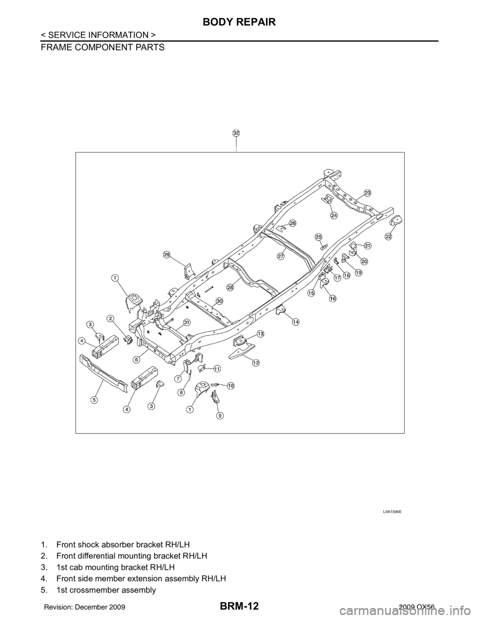
1. Front shock absorber bracket RH/LH
2. Front differential mounting bracket RH/LH
3. 1st cab mounting bracket RH/LH
4. Front side member extension assembly RH/LH
5. 1st crossmember assembly
LIIA1594E
Revision: December 20092009 QX56
Page 609 of 4171
BODY REPAIRBRM-13
< SERVICE INFORMATION >
C
DE
F
G H
I
J
L
M A
B
BRM
N
O P
6. 2nd crossmember assembly
7. Front upper link mounting bracket RH/LH
8. Panhard rod bracket reinforcement
9. Bound bumper bracket RH/LH
10. Front brake hose bracket RH/LH
11. Panhard rod reinforcement
12. 4th crossmember gusset RH/LH
13. 2nd cab mounting bracket RH/LH
14. 3rd cab mounting bracket RH/LH
15. 4th cab mounting reinforcement RH/LH
16. 4th cab mounting bracket RH/LH
17. Rear suspension mounting bracket RH/LH
18. Rear brake hose bracket
19. Rear shock absorber bracket assembly RH/LH
20. Rear bound bumper bracket RH/LH
21. Rear bracket bumper reinforcement RH/LH
22. Cab mounting bracket assembly RH/LH
23. 9th crossmember assembly
24. Exhaust bracket assembly
25. Canister bracket, LH
26. 7th crossmember reinforcement
27. 7th crossmember assembly
28. 6th crossmember assembly
29. 4th crossmember gusset RH/LH
30. 4th crossmember assembly
31. 3rd crossmember assembly
32. Frame assembly
Corrosion ProtectionINFOID:0000000003776120
DESCRIPTION
To provide improved corrosion prevention, the follo wing anti-corrosive measures have been implemented in
NISSAN production plants. When repairing or replacing body panels, it is necessary to use the same anti-cor-
rosive measures.
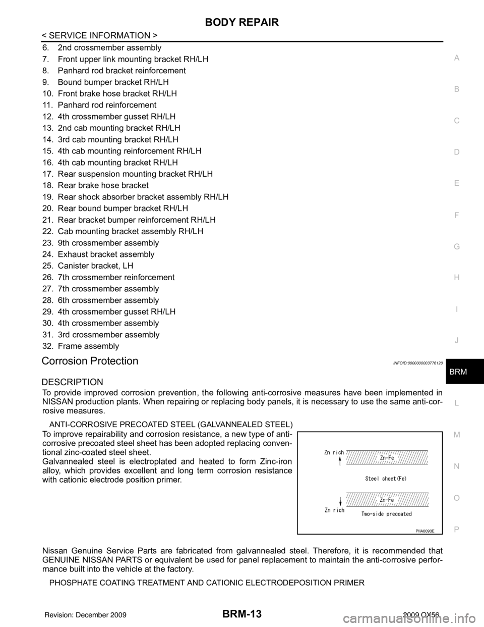
ANTI-CORROSIVE PRECOATED ST EEL (GALVANNEALED STEEL)
To improve repairability and corrosion resistance, a new type of anti-
corrosive precoated steel sheet has been adopted replacing conven-
tional zinc-coated steel sheet.
Galvannealed steel is electroplated and heated to form Zinc-iron
alloy, which provides excellent and long term corrosion resistance
with cationic electrode position primer.
Nissan Genuine Service Parts are fabricated from galvannealed steel. Therefore, it is recommended that
GENUINE NISSAN PARTS or equivalent be used for panel replacement to maintain the anti-corrosive perfor-
mance built into the vehicle at the factory.
PHOSPHATE COATING TREATMENT AND CA TIONIC ELECTRODEPOSITION PRIMER
PIIA0093E
Revision: December 20092009 QX56
Page 610 of 4171
BRM-14
< SERVICE INFORMATION >
BODY REPAIR
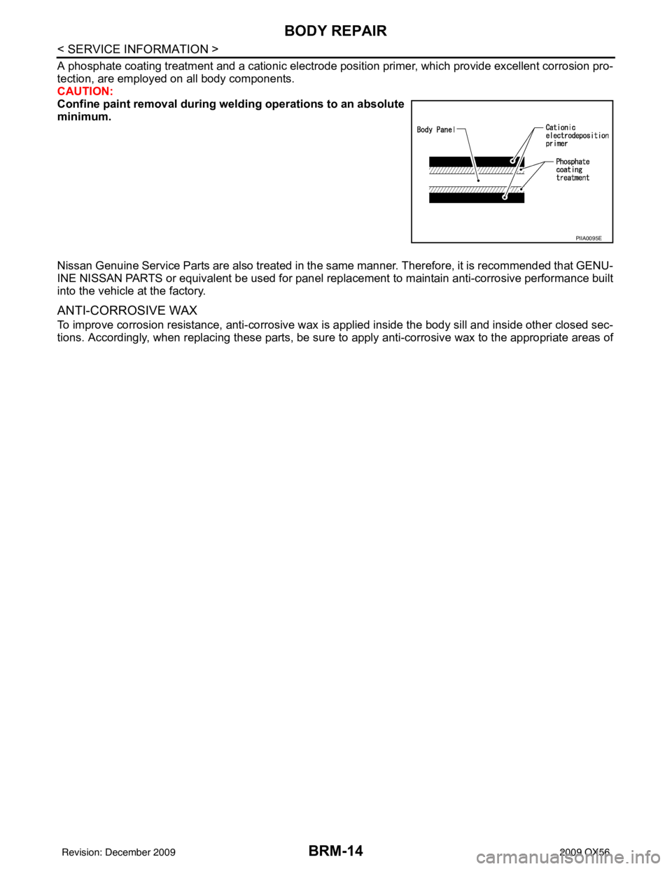
A phosphate coating treatment and a cationic electrode position primer, which provide excellent corrosion pro-
tection, are employed on all body components.
CAUTION:
Confine paint removal during welding operations to an absolute
minimum.
Nissan Genuine Service Parts are also treated in the same manner. Therefore, it is recommended that GENU-
INE NISSAN PARTS or equivalent be used for panel replacement to maintain anti-corrosive performance built
into the vehicle at the factory.
ANTI-CORROSIVE WAX
To improve corrosion resistance, anti-corrosive wax is applied inside the body sill and inside other closed sec-
tions. Accordingly, when replacing these parts, be sure to apply anti-corrosive wax to the appropriate areas of
PIIA0095E
Revision: December 20092009 QX56
Page 652 of 4171

CCS-1
CRUISE CONTROL
C
DE
F
G H
I
J
K L
M B
CCS
SECTION CCS
N
P A
CONTENTS
CRUISE CONTROL SYSTEM
BASIC INSPECTION ....... .............................3
DIAGNOSIS AND REPAIR WORKFLOW ..... .....3
Work Flow ........................................................... ......3
INSPECTION AND ADJUSTMENT .....................5
ADDITIONAL SERVICE WHEN REPLACING
CONTROL UNIT .................................................... ......
5
ADDITIONAL SERVICE WHEN REPLACING
CONTROL UNIT : Description ..................................
5
ADDITIONAL SERVICE WHEN REPLACING
CONTROL UNIT : Special Repair Requirement .......
5
LASER BEAM AIMING ADJUSTMENT ................ ......5
LASER BEAM AIMING ADJUSTMENT : Outline
of Laser Beam Aiming Adjustment Procedure ..........
5
LASER BEAM AIMING ADJUSTMENT : Prepara-
tion ...................................................................... ......
5
LASER BEAM AIMING ADJUSTMENT : Setting
up the ICC Target Board ...........................................
6
LASER BEAM AIMING ADJUSTMENT : Sensor
Adjustment ................................................................
7
ACTION TEST ....................................................... ......8
ACTION TEST : ICC System Running Test ..............8
FUNCTION DIAGNOSIS ..............................12
AUTOMATIC SPEED CONTROL DEVICE
(ASCD) ........................................................... ....
12
System Description ............................................. ....12
INTELLIGENT CRUISE CONTROL SYSTEM ....13
System Diagram .................................................. ....13
System Description .................................................13
Component Parts Location ......................................15
Component Description ...........................................16
DIAGNOSIS SYSTEM (ICC SENSOR INTE-
GRATED UNIT) ..................................................
17
Diagnosis Description ......................................... ....17
CONSULT-III Function (ICC) ............................... ....18
COMPONENT DIAGNOSIS .........................22
DTC 11 CONTROL UNIT ..................................22
DTC 11 CONTROL UNIT .................................... ....22
DTC 12 VDC CONTROL UNIT ..........................23
DTC 12 VDC CONTROL UNIT ................................23
DTC 20 CAN COMM CIRCUIT ..........................24
DTC 20 CAN COMM CIRCUIT ................................24
DTC 31 POWER SUPPLY CIR1, DTC 34
POWER SUPPLY CIR2 .....................................
25
DTC 31 POWER SUPPLY CIR1, DTC 34 POWER
SUPPLY CIR2 .........................................................
25
DTC 41 VHCL SPEED SE CIRC .......................26
DTC 41 VHCL SPEED SE CIRC .............................26
DTC 43 VDC/TCS/ABS CIRC ...........................27
DTC 43 VDC/TCS/ABS CIRC .................................27
DTC 45 BRAKE SW/STOP L SW .....................28
DTC 45 BRAKE SW/STOP L SW ............................28
DTC 46 OPERATION SW CIRC .......................30
DTC 46 OPERATION SW CIRC ......................... ....30
DTC 74 LASER BEAM OFF CNTR ..................31
DTC 74 LASER BEAM OFF CNTR .........................31
DTC 90 STOP LAMP RLY FIX ..........................32
DTC 90 STOP LAMP RLY FIX ................................32
DTC 92 ECM CIRCUIT ......................................37
DTC 92 ECM CIRCUIT ............................................37
DTC 96 NP RANGE ..........................................38
DTC 96 NP RANGE ............................................ ....38
DTC 97 AT CIRCUIT .........................................39
DTC 97 AT CIRCUIT ...............................................39
Revision: December 20092009 QX56
Page 667 of 4171
CCS-16
< FUNCTION DIAGNOSIS >
INTELLIGENT CRUISE CONTROL SYSTEM
Component Description
INFOID:0000000003776934
× : Applicable
Component Veh ic le-t o-
vehicle
distance
control mode Conventional
(Fixed speed)
cruise
control mode Brake assist
(With preview function) Description
ICC unit ××× Controls vehicle speed through ECM via CAN commu-
nication.
ICC sensor ××× Measures distance to objects in front of the vehicle and
transmits that information to the ICC unit.
ECM ××× Refer to EC-21, "
System Diagram".
ABS actuator and electric
unit (control unit) ×××
Refer to BRC-18, "
System Description".
Brake pressure sensor ×× Detects brake fluid pressure.
Brake booster ×× Adjusts brake fluid pressure based on command from
ABS actuator and electric unit (control unit).
BCM × Transmits front wiper request signal to ICC sensor inte-
grated unit through CAN communication.
TCM ×× Refer to TM-20, "
TCM Function".
Revision: December 20092009 QX56
Page 669 of 4171
CCS-18
< FUNCTION DIAGNOSIS >
DIAGNOSIS SYSTEM (ICC SENSOR INTEGRATED UNIT)
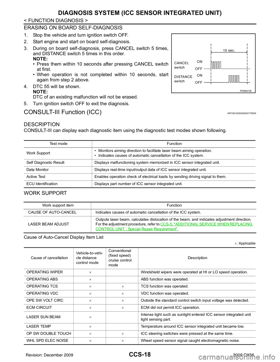
ERASING ON BOARD SELF-DIAGNOSIS
1. Stop the vehicle and turn ignition switch OFF.
2. Start engine and start on board self-diagnosis.
3. During on board self-diagnosis, press CANCEL switch 5 times,
and DISTANCE switch 5 times in this order.
NOTE:
• Press them within 10 seconds after pressing CANCEL switch
at first.
• When operation is not completed within 10 seconds, start again from step 2 above.
4. DTC 55 will be shown. NOTE:
DTC of an existing malfunction will not be erased.
5. Turn ignition switch OFF to exit the diagnosis.
CONSULT-III Function (ICC)INFOID:0000000003776936
DESCRIPTION
CONSULT-III can display each diagnostic item us ing the diagnostic test modes shown following.
WORK SUPPORT
Cause of Auto-Cancel Display Item List
×: Applicable
PKIB8373E
Test mode Function
Work Support • Monitors aiming direction to facilitate laser beam aiming operation.
• Indicates causes of automatic cancellation of the ICC system.
Self Diagnostic Result Displays malfunctioning system memorized in ICC sensor integrated unit.
Data Monitor Displays real-time input/output data of ICC sensor integrated unit.
Active Test Enables operation check of electrical loads by sending driving signal to them.
ECU Identification Displays part number of ICC sensor integrated unit.
Work support item Function
CAUSE OF AUTO-CANCEL Indicates causes of automatic cancellation of the ICC system.
LASER BEAM ADJUST Outputs laser beam, calculates dislocation of the beam, and indicates adjustment direction.
For the adjustment procedure, refer to
CCS-5, "
ADDITIONAL SERVICE WHEN REPLACING
CONTROL UNIT : Special Repair Requirement".
Cause of cancellationVehicle-to-vehi-
cle distance
control modeConventional
(fixed speed)
cruise control
mode
Description
OPERATING WIPER ×Windshield wipers were operated at HI or LO speed operation.
OPERATING ABS ×ABS function was operated.
OPERATING TCS ××TCS function was operated.
OPERATING VDC ××VDC function was operated.
OPE SW VOLT CIRC ××Outside the standard control switch input voltage was detected.
ECM CIRCUIT ××ECM did not permit ICC operation.
LASER SUN BEAM ×Intense light such as sunlight entered ICC sensor integrated unit
light sensing part.
LASER TEMP ×Temperature around ICC sensor integrated unit became low.
OP SW DOUBLE TOUCH ××ICC steering switches were pressed at the same time.
WHL SPD ELEC NOISE ××Wheel speed sensor signal caught electromagnetic noise.
Revision: December 20092009 QX56
Page 670 of 4171
CCS
DIAGNOSIS SYSTEM (ICC SENSOR INTEGRATED UNIT)
CCS-19
< FUNCTION DIAGNOSIS >
C
D E
F
G H
I
J
K L
M B
N P A
• Last five cancel (system cancel) causes are displayed.
• “CAUSE OF AUTO-CANCEL” displays times of ignition switch ON/OFF up to 254 maximum. 254 is kept though the number exceeds 254. The num ber returns to 0 when detecting the same cancellation causes.
SELF DIAGNOSTIC RESULT
For details, refer to CCS-55, "Diagnostic Trouble Code (DTC) Chart".
NOTE:
“DTC RESULTS” and “TIME” are indicated on “Self Diagnostic Result”. “TIME” is used as a reference data of
diagnosis. It shows when malfunction is detected.
“TIME” shows the following.
• 0: malfunction is detected at present (from malfunction detection to ignition switch OFF).
CAN communication ([U1000], [U1010])
• 1 ~ 39: Displays when it is normal at present and finds malfunction in the past. It increases like
0→ 1→ 2...38→ 39 after returning to the normal condition whenever IGN OFF→ ON. If it is over 39, it is fixed to
39 until the self-diagnostic results are erased. It retu rns to 0 when malfunction is detected again in the pro-
cess.
Other than CAN communication (other than [U1000], [U1010])
• 1 ~ 49: Displays when it is normal at present and finds malfunction in the past. It increases like 0→ 1→ 2...48→ 49 after returning to the normal condition whenever IGN OFF→ ON. If it is over 49, it is fixed to
49 until the self-diagnostic results are erased. It retu rns to 0 when malfunction is detected again in the pro-
cess.
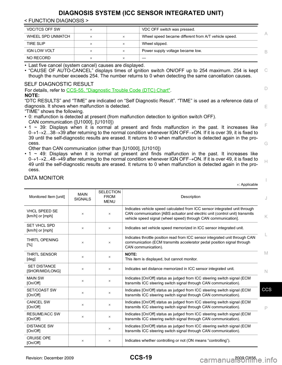
DATA MONITOR
× : Applicable
VDC/TCS OFF SW ×VDC OFF switch was pressed.
WHEEL SPD UNMATCH ××Wheel speed became different from A/T vehicle speed.
TIRE SLIP ××Wheel slipped.
IGN LOW VOLT ××Power supply voltage became low.
NO RECORD ××—
Monitored Item [unit]MAIN
SIGNALS SELECTION
FROM
MENU Description
VHCL SPEED SE
[km/h] or [mph] ××Indicates vehicle speed calculated from ICC sensor integrated unit through
CAN communication [ABS actuator and electric unit (control unit) transmits
vehicle speed signal (wheel speed) through CAN communication].
SET VHCL SPD
[km/h] or [mph] ××
Indicates set vehicle speed memorized in ICC sensor integrated unit.
THRTL OPENING
[%] ××Indicates throttle position read from ICC sensor integrated unit through CAN
communication (ECM transmits accelerator pedal position signal through
CAN communication).
THRTL SENSOR
[deg] ××NOTE:
This item is displayed, but cannot monitor.
SET DISTANCE
[SHOR/MID/LONG] ××
Indicates set distance memorized in ICC sensor integrated unit.
MAIN SW
[On/Off] ××
Indicates [On/Off] status as judged from ICC steering switch signal (ECM
transmits ICC steering switch signal through CAN communication).
SET/COAST SW
[On/Off] ××Indicates [On/Off] status as judged from ICC steering switch signal (ECM
transmits ICC steering switch signal through CAN communication).
CANCEL SW
[On/Off] ××Indicates [On/Off] status as judged from ICC steering switch signal (ECM
transmits ICC steering switch signal through CAN communication).
RESUME/ACC SW
[On/Off] ××
Indicates [On/Off] status as judged from ICC steering switch signal (ECM
transmits ICC steering switch signal through CAN communication).
DISTANCE SW
[On/Off] ×Indicates [On/Off] status as judged from ICC steering switch signal (ECM
transmits ICC steering switch signal through CAN communication).
CRUISE OPE
[On/Off] ××
Indicates whether controlling or not (ON means “controlling”).
Revision: December 20092009 QX56
Page 674 of 4171
CCS
DTC 12 VDC CONTROL UNITCCS-23
< COMPONENT DIAGNOSIS >
C
DE
F
G H
I
J
K L
M B
N P A
DTC 12 VDC CONTROL UNIT
DTC 12 VDC CONTROL UNITINFOID:0000000003776938
1.DIAGNOSIS CHECK
Perform self-diagnosis of ABS actuator and electric unit (control unit).
Is malfunction indicated?
YES >> Repair or replace as necessary. Erase DTC and perform ICC system running test. Refer to CCS-
8, "ACTION TEST : ICC System Running Test".
NO >> GO TO 2
2.CHECK CONNECTOR ICC UNIT AND ABS ACTUATOR AND ELECTRIC UNIT (CONTROL UNIT)
1. Turn ignition switch OFF.
2. Disconnect ICC unit, and ABS act uator and electric unit (control unit) connectors, and connect them
securely again. Erase DTC, then perform self-diagnosis of ICC system again.
Does the DTC return?
YES >> Poor connector connection. Check connector hous ing for disconnected, loose, bent and collapsed
terminals. If any malfunction is detected, repa ir as necessary. Erase DTC and perform ICC sys-
tem running test. Refer to CCS-8, "
ACTION TEST : ICC System Running Test".
NO >> GO TO 3
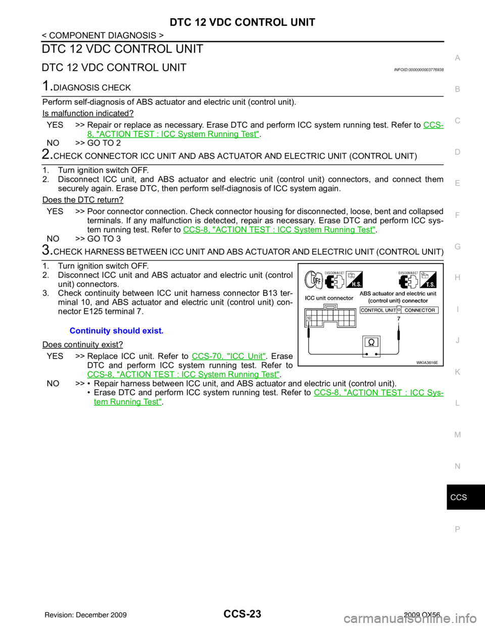
3.CHECK HARNESS BETWEEN ICC UNIT AND ABS AC TUATOR AND ELECTRIC UNIT (CONTROL UNIT)
1. Turn ignition switch OFF.
2. Disconnect ICC unit and ABS actuat or and electric unit (control
unit) connectors.
3. Check continuity between ICC unit harness connector B13 ter-
minal 10, and ABS actuator and electric unit (control unit) con-
nector E125 terminal 7.
Does continuity exist?
YES >> Replace ICC unit. Refer to CCS-70, "ICC Unit". Erase
DTC and perform ICC system running test. Refer to
CCS-8, "
ACTION TEST : ICC System Running Test".
NO >> • Repair harness between ICC unit, and ABS actuator and electric unit (control unit).
• Erase DTC and perform ICC system running test. Refer to CCS-8, "
ACTION TEST : ICC Sys-
tem Running Test".
Continuity should exist.
WKIA3616E
Revision: December 20092009 QX56