INFINITI QX56 2009 Factory Service Manual
Manufacturer: INFINITI, Model Year: 2009, Model line: QX56, Model: INFINITI QX56 2009Pages: 4171, PDF Size: 84.65 MB
Page 2221 of 4171

PRECAUTIONSGI-27
< PRECAUTION >
C
DE
F
G H
I
J
K L
M B
GI
N
O P
system. The connectors should be disconnected only when working according to the WORK FLOW of
TROUBLE DIAGNOSES in EC and TM sections.
Three Way CatalystINFOID:0000000003771200
If a large amount of unburned fuel flows into the catalyst, the catalyst temperature will be excessively high. To
prevent this, follow the instructions.
• Use unleaded gasoline only. Leaded gasoline will seriously damage the three way catalyst.
• When checking for ignition spark or measuring engine compression, make tests quickly and only when nec-
essary.
• Do not run engine when the fuel tank level is low, otherwise the engine may misfire, causing damage to the
catalyst.
Do not place the vehicle on flammable material. Keep flammable material off the exhaust pipe and the three
way catalyst.
Precaution for Fuel (Unlead ed Premium Gasoline Recommended)INFOID:0000000005892332
NISSAN/INFINITI recommends the us e of unleaded premium gasoline with an octane rating of at least 91 AKI
(Anti-Knock Index) number (Research octane number 96). If unleaded premium gasoline is not available,
unleaded regular gasoline with an octane rating of at least 87 AKI number (Research octane number 91), but
you may notice a decrease in performance.
CAUTION:
Do not use leaded gasoline. Usin g leaded gasoline will damage the three way catalyst. Using a fuel
other than that specified could adversely affect the emission cont rol devices and systems, and could
also affect the warranty coverage validity.
CAUTION:
Do not use E-85 fuel in your vehicle. Your vehicle is not designed to run on E-85 fuel. Using E-85 fuel
can cause damage to the fuel system components an d is not covered by the INFINTI vehicle limited
warranty.
Multiport Fuel Inje ction System or Engine Control SystemINFOID:0000000003771202
• Before connecting or disconnecting any harness connector for the
multiport fuel injection system or ECM:
Turn ignition switch to “OFF” position.
Disconnect negative battery terminal.
Otherwise, there may be damage to ECM.
• Before disconnecting pressurized fuel line from fuel pump to injec- tors, be sure to release fuel pressure.
• Be careful not to jar components such as ECM and mass air flow sensor.
HosesINFOID:0000000003771203
HOSE REMOVAL AND INSTALLATION
• To prevent damage to rubber hose, do not pry off rubber hose withtapered tool or screwdriver.
SGI787
SMA019D
Revision: December 20092009 QX56
Page 2222 of 4171

GI-28
< PRECAUTION >
PRECAUTIONS
• To reinstall the rubber hose securely, make sure that hose insertionlength and orientation is correct. (If tube is equipped with hose
stopper, insert rubber hose into tube until it butts up against hose
stopper.)
HOSE CLAMPING
• If old rubber hose is re-used, install hose clamp in its original posi-tion (at the indentation where the old clamp was). If there is a trace
of tube bulging left on the old rubber hose, align rubber hose at
that position.
• Discard old clamps; replace with new ones.
• After installing plate clamps, apply force to them in the direction of the arrow, tightening rubber hose equally all around.
Engine OilsINFOID:0000000003771204
Prolonged and repeated contact with used engine oil may cause skin cancer. Try to avoid direct skin contact
with used oil.
If skin contact is made, wash thoroughly with soap or hand cleaner as soon as possible.
HEALTH PROTECTION PRECAUTIONS
• Avoid prolonged and repeated contact with oils, particularly used engine oils.
• Wear protective clothing, including impervious gloves where practicable.
• Do not put oily rags in pockets.
• Avoid contaminating clothes, pa rticularly underpants, with oil.
• Heavily soiled clothing and oil-impregnated footwear should not be worn. Overalls must be cleaned regu- larly.
• First aid treatment should be obtained immediately for open cuts and wounds.
• Use barrier creams, applying them before each work period, to help the removal of oil from the skin.
• Wash with soap and water to ensure all oil is removed (skin cleansers and nail brushes will help). Prepara-
tions containing lanolin replace the natural skin oils which have been removed.
• Do not use gasoline, kerosene, diesel fuel, gas oil, thinners or solvents for cleaning skin.
• If skin disorders develop, obtain medical advice without delay.
• Where practical, degrease components prior to handling.
• Where there is a risk of eye contact, eye protection should be worn, for example, chemical goggles or face
shields; in addition an eye wash facility should be provided.
ENVIRONMENTAL PROTECTION PRECAUTIONS
SMA020D
SMA021D
SMA022D
Revision: December 20092009 QX56
Page 2223 of 4171
PRECAUTIONSGI-29
< PRECAUTION >
C
DE
F
G H
I
J
K L
M B
GI
N
O P
Dispose of used oil and used oil filters through authorized waste disposal contractors to licensed waste dis-
posal sites, or to the waste oil reclamation trade. If in doubt, contact the local authority for advice on disposal
facilities.
It is illegal to pour used oil on to the ground, down sewers or drains, or into water sources.
The regulations concerning po llution vary between regions.
Air ConditioningINFOID:0000000003771205
Use an approved refrigerant recovery unit any time t he air conditioning system must be discharged. Refer to
HA-20, "
HFC-134a (R-134a) Service Procedure".
Revision: December 20092009 QX56
Page 2224 of 4171
GI-30
< PRECAUTION >
LIFTING POINT
LIFTING POINT
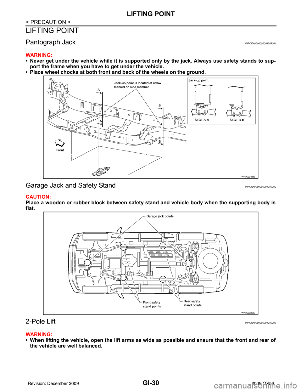
Pantograph JackINFOID:0000000004209201
WARNING:
• Never get under the vehicle while it is supported only by the jack. Always use safety stands to sup-
port the frame when you have to get under the vehicle.
• Place wheel chocks at both front an d back of the wheels on the ground.
Garage Jack and Safety StandINFOID:0000000004209202
CAUTION:
Place a wooden or rubber block between safety stand and vehicle body when the supporting body is
flat.
2-Pole LiftINFOID:0000000004209203
WARNING:
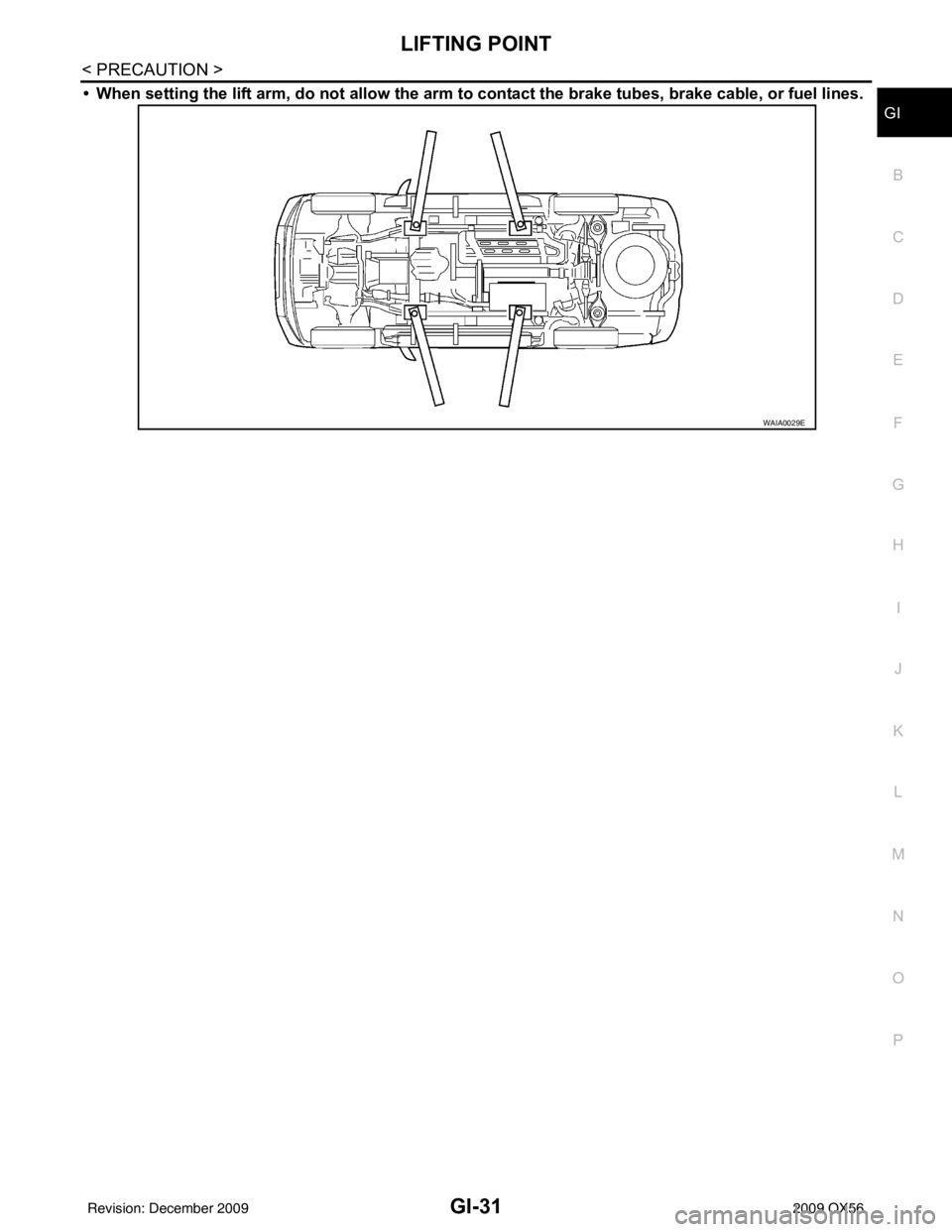
• When lifting the vehicle, open the lift arms as wid e as possible and ensure that the front and rear of
the vehicle are well balanced.
WAIA0041E
WAIA0028E
Revision: December 20092009 QX56
Page 2225 of 4171
LIFTING POINTGI-31
< PRECAUTION >
C
DE
F
G H
I
J
K L
M B
GI
N
O P
• When setting the lift arm, do not allow the arm to contact the brake tubes, brake cable, or fuel lines.
WAIA0029E
Revision: December 20092009 QX56
Page 2226 of 4171
GI-32
< PRECAUTION >
TOW TRUCK TOWING
TOW TRUCK TOWING
Tow Truck TowingINFOID:0000000005867507
WARNING:
• Never get under the vehicle while it is supported only by the jack. Always use safety stands to sup-
port the frame when you have to get under the vehicle.
• Place wheel chocks at both front an d back of the wheels on the ground.
CAUTION:
• All applicable State or Provincial (in Canada) laws and local laws regarding the towing operation
must be obeyed.
• It is necessary to use proper towing equipment to avoid possible damage during towing operation.
Towing is in accordance with Towing Procedure Manual at dealer.
• Always attach safety chains before towing.
• When towing, make sure that the transmission, steering system and powertrain are in good order. If any unit is damaged, dollies must be used.
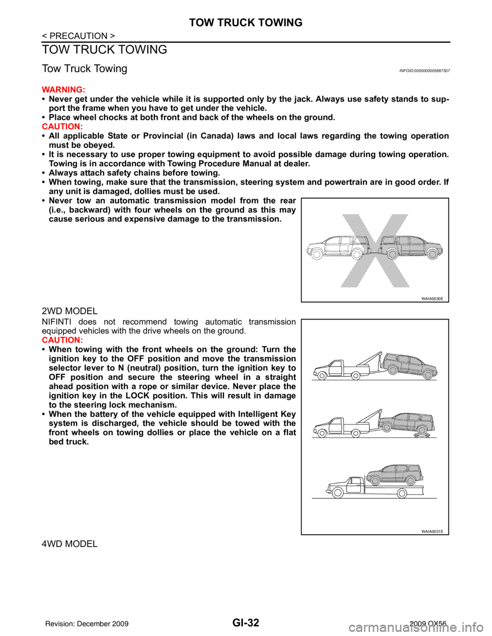
• Never tow an automatic transmission model from the rear (i.e., backward) with four wh eels on the ground as this may
cause serious and expensive dama ge to the transmission.
2WD MODEL
NIFINTI does not recommend towing automatic transmission
equipped vehicles with the drive wheels on the ground.
CAUTION:
• When towing with the front wheels on the ground: Turn the
ignition key to the OFF posit ion and move the transmission
selector lever to N (neutral) pos ition, turn the ignition key to
OFF position and secure the steering wheel in a straight
ahead position with a rope or similar device. Never place the
ignition key in the LOCK position. This will result in damage
to the steering lock mechanism.
• When the battery of the vehicle equipped with Intelligent Key system is discharged, the vehicle should be towed with the
front wheels on towing dollies or place the vehicle on a flat
bed truck.
4WD MODEL
WAIA0030E
WAIA0031E
Revision: December 20092009 QX56
Page 2227 of 4171

TOW TRUCK TOWINGGI-33
< PRECAUTION >
C
DE
F
G H
I
J
K L
M B
GI
N
O P
INIFINTI recommends that towing dollies be used when towing 4WD
equipped vehicles or place the vehicle on a flat bed truck.
CAUTION:
• Never tow 4WD models with any of the wheels on the ground as this may cause serious and expensive damage to the
transfer case and transmission.
Towing Point
CAUTION:
Never tow the vehicle using only the towing points. To avoid
damaging the vehicle body, use proper towing equipment when
towing.
Vehicle Recovery (Freeing a stuck vehicle)INFOID:0000000005867508
•Tow chains or cables must be attached only to the main structural members of the vehicle.
• Pulling devices should be routed so they do not touch any part of the suspension, steering, brake or
cooling systems
• Always pull the cable straight out from the front or rear of the vehicle. Never pull the vehicle at a
sideways angle.
• Pulling devices such as ropes or canvas straps are not recommended for use for vehicle towing or
recovery.
WAIA0032E
AWAIA0027GB
Revision: December 20092009 QX56
Page 2228 of 4171
GI-34
< BASIC INSPECTION >
SERVICE INFORMATION FOR ELECTRICAL INCIDENT
BASIC INSPECTION
SERVICE INFORMATION FOR ELECTRICAL INCIDENT
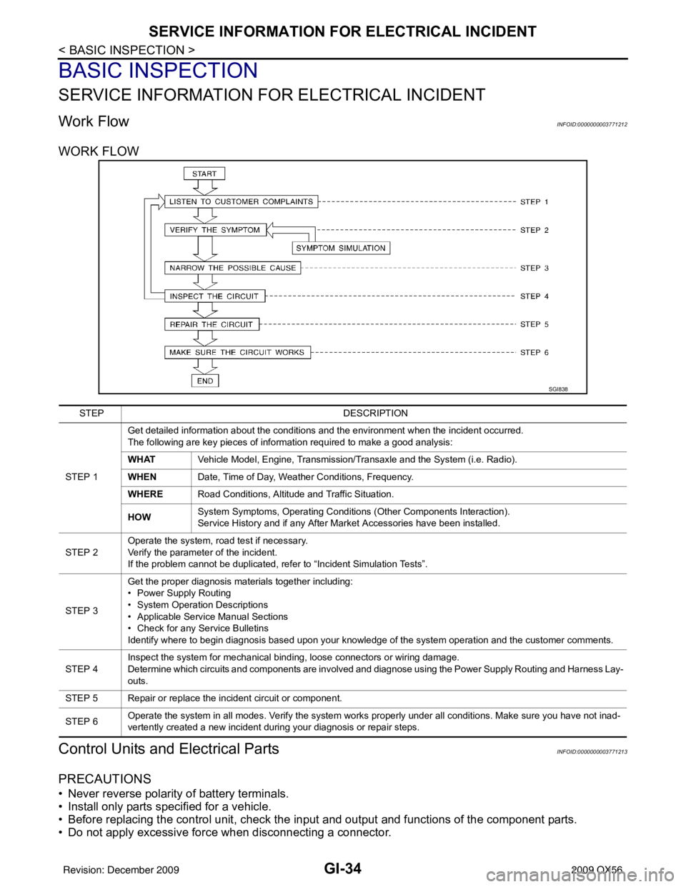
Work FlowINFOID:0000000003771212
WORK FLOW
Control Units and Electrical PartsINFOID:0000000003771213
PRECAUTIONS
• Never reverse polarity of battery terminals.
• Install only parts specified for a vehicle.
• Before replacing the control unit, check the i nput and output and functions of the component parts.
• Do not apply excessive force when disconnecting a connector.
SGI838
STEP DESCRIPTION
STEP 1 Get detailed information about the conditions and the environment when the incident occurred.
The following are key pieces of information required to make a good analysis:
WHAT
Vehicle Model, Engine, Transmission/Transaxle and the System (i.e. Radio).
WHEN Date, Time of Day, Weather Conditions, Frequency.
WHERE Road Conditions, Altitude and Traffic Situation.
HOW System Symptoms, Operating Conditions
(Other Components Interaction).
Service History and if any After Market Accessories have been installed.
STEP 2 Operate the system, road test if necessary.
Verify the parameter of the incident.
If the problem cannot be duplicated, refer to “Incident Simulation Tests”.
STEP 3 Get the proper diagnosis materials together including:
• Power Supply Routing
• System Operation Descriptions
• Applicable Service Manual Sections
• Check for any Service Bulletins
Identify where to begin diagnosis based upon your knowledge of the system operation and the customer comments.
STEP 4 Inspect the system for mechanical binding, loose connectors or wiring damage.
Determine which circuits and components are involved and diagnose using the Power Supply Routing and Harness Lay-
outs.
STEP 5 Repair or replace the incident circuit or component.
STEP 6 Operate the system in all modes. Verify the system works properly under all conditions. Make sure you have not inad-
vertently created a new incident during your diagnosis or repair steps.
Revision: December 20092009 QX56
Page 2229 of 4171
SERVICE INFORMATION FOR ELECTRICAL INCIDENTGI-35
< BASIC INSPECTION >
C
DE
F
G H
I
J
K L
M B
GI
N
O P
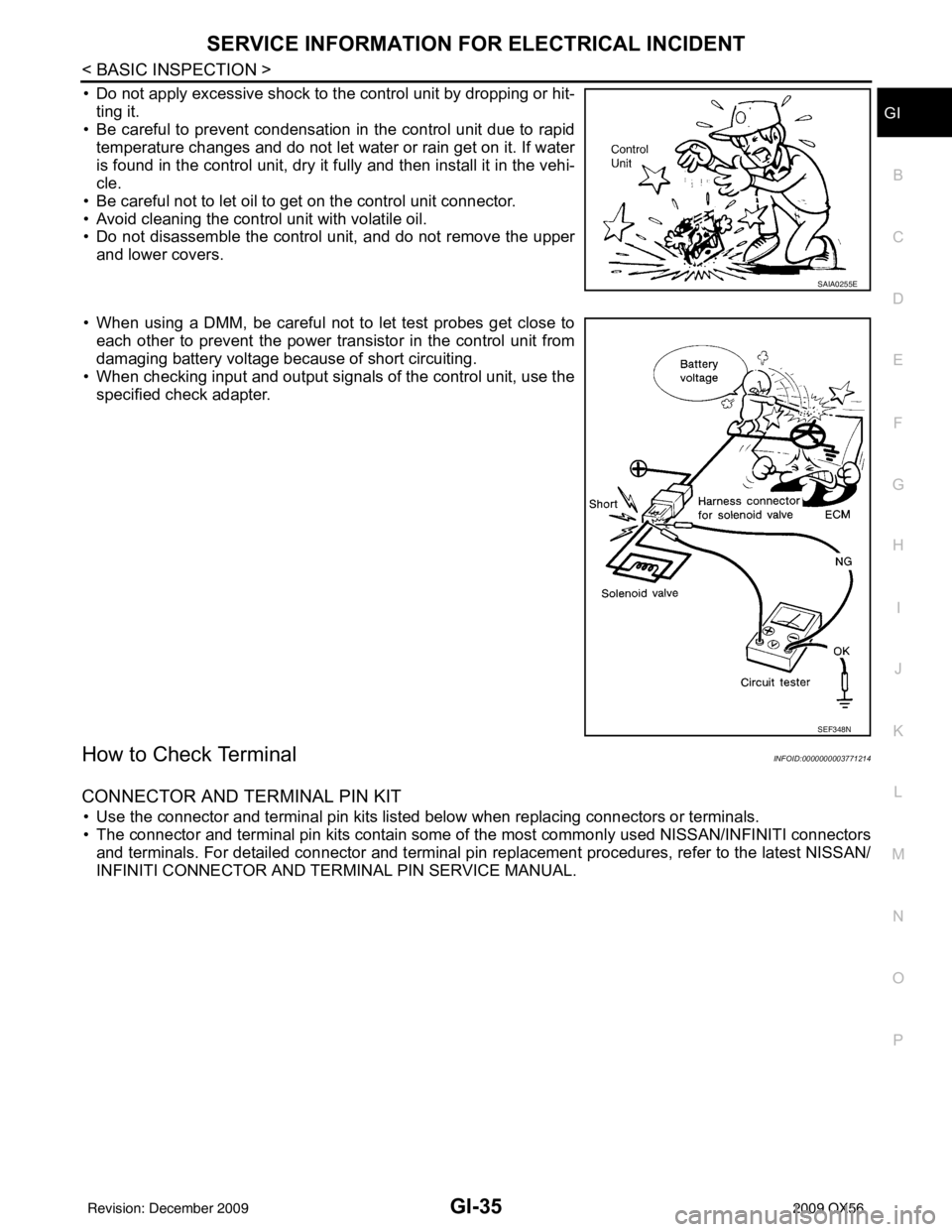
• Do not apply excessive shock to the control unit by dropping or hit- ting it.
• Be careful to prevent condensation in the control unit due to rapid
temperature changes and do not let water or rain get on it. If water
is found in the control unit, dry it fully and then install it in the vehi-
cle.
• Be careful not to let oil to get on the control unit connector.
• Avoid cleaning the control unit with volatile oil.
• Do not disassemble the control unit, and do not remove the upper and lower covers.
• When using a DMM, be careful not to let test probes get close to each other to prevent the power transistor in the control unit from
damaging battery voltage because of short circuiting.
• When checking input and output signals of the control unit, use the specified check adapter.
How to Check TerminalINFOID:0000000003771214
CONNECTOR AND TERMINAL PIN KIT
• Use the connector and terminal pin kits listed below when replacing connectors or terminals.
• The connector and terminal pin kits contain some of the most commonly used NISSAN/INFINITI connectors
and terminals. For detailed connector and terminal pin r eplacement procedures, refer to the latest NISSAN/
INFINITI CONNECTOR AND TERMINAL PIN SERVICE MANUAL.
SAIA0255E
SEF348N
Revision: December 20092009 QX56
Page 2230 of 4171
GI-36
< BASIC INSPECTION >
SERVICE INFORMATION FOR ELECTRICAL INCIDENT
HOW TO PROBE CONNECTORS
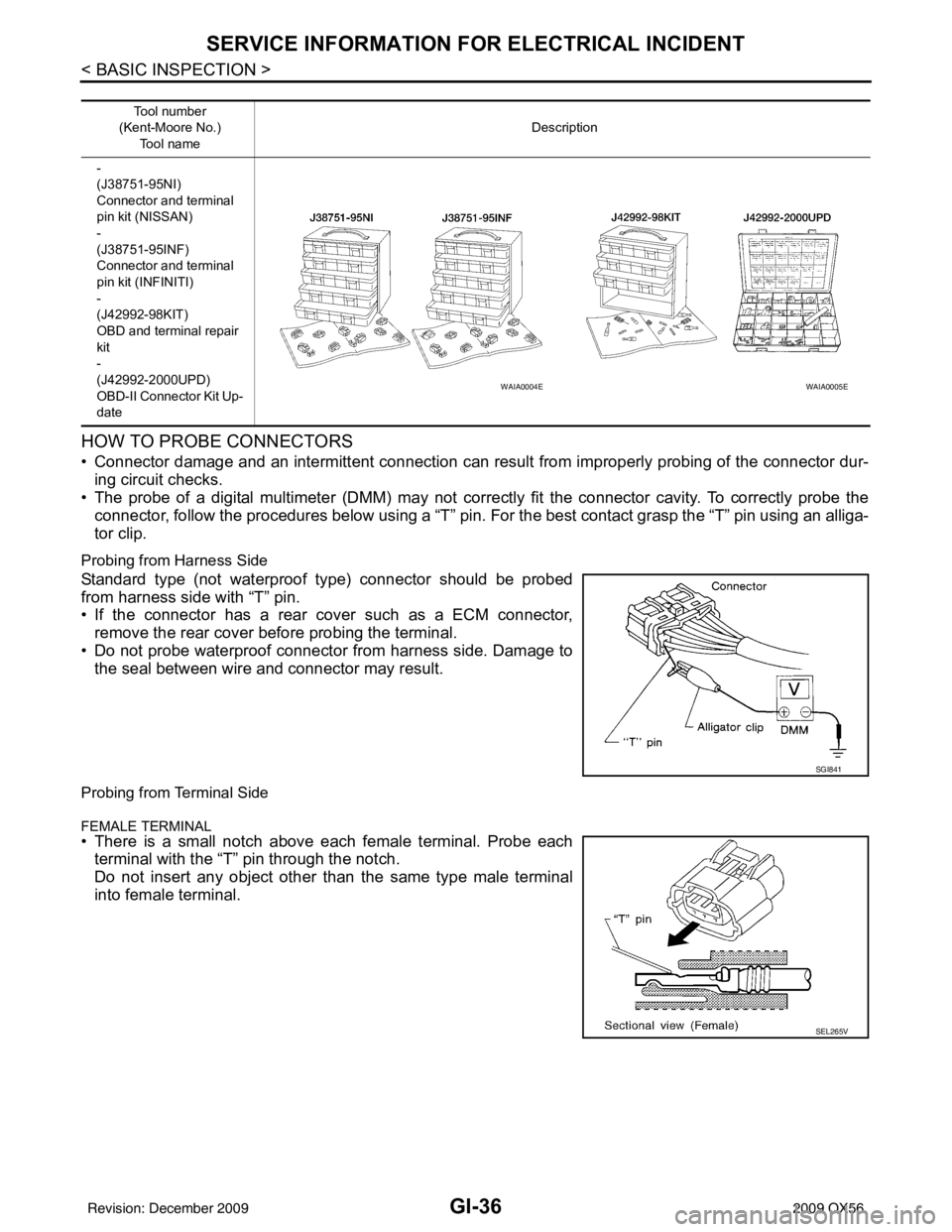
• Connector damage and an intermittent connection can result from improperly probing of the connector dur-ing circuit checks.
• The probe of a digital multimeter (DMM) may not correctly fit the connector cavity. To correctly probe the connector, follow the procedures below using a “T” pin. For the best contact grasp the “T” pin using an alliga-
tor clip.
Probing from Harness Side
Standard type (not waterproof type) connector should be probed
from harness side with “T” pin.
• If the connector has a rear cover such as a ECM connector,remove the rear cover before probing the terminal.
• Do not probe waterproof connector from harness side. Damage to the seal between wire and connector may result.
Probing from Terminal Side
FEMALE TERMINAL
• There is a small notch above each female terminal. Probe each
terminal with the “T” pin through the notch.
Do not insert any object other than the same type male terminal
into female terminal.
Tool number
(Kent-Moore No.) Tool name Description
-
(J38751-95NI)
Connector and terminal
pin kit (NISSAN)
-
(J38751-95INF)
Connector and terminal
pin kit (INFINITI)
-
(J42992-98KIT)
OBD and terminal repair
kit
-
(J42992-2000UPD)
OBD-II Connector Kit Up-
date
WAIA0004EWAIA0005E
SGI841
SEL265V
Revision: December 20092009 QX56