INFINITI QX56 2009 Factory Service Manual
Manufacturer: INFINITI, Model Year: 2009, Model line: QX56, Model: INFINITI QX56 2009Pages: 4171, PDF Size: 84.65 MB
Page 2251 of 4171

PRECAUTIONSGW-9
< PRECAUTION >
C
DE
F
G H
I
J
L
M A
B
GW
N
O P
5. When the repair work is completed, return the ignition switch to the ″LOCK ″ position before connecting
the battery cables. (At this time, the steering lock mechanism will engage.)
6. Perform a self-diagnosis check of al l control units using CONSULT-III.
Handling for Adhesive and PrimerINFOID:0000000005867454
• Do not use an adhesive which is past its usable date. Shelf life of this product is limited to six months after
the date of manufacture. Carefully adhere to the ex piration or manufacture date printed on the box.
• Keep primers and adhesive in a cool, dry place. I deally, they should be stored in a refrigerator.
• Open the seal of the primer and adhesive just before application. Discard the remainder.
• Before application, be sure to shake the primer container to stir the contents. If any floating material is found,
do not use it.
• If any primer or adhesive contacts the skin, wipe it off with gasoline or equivalent and wash the skin with
soap.
• When using primer and adhesive, always observe the precautions in the instruction manual.
Revision: December 20092009 QX56
Page 2252 of 4171

GW-10
< PREPARATION >
PREPARATION
PREPARATION
PREPARATION
Special Service ToolINFOID:0000000005864611
The actual shapes of Kent-Moore tools may differ from those of special service tools illustrated here.
Commercial Service ToolINFOID:0000000005864612
Tool number
(Kent-Moore No.)
Tool name Description
—
(J-39570)
Chassis ear Locating the noise
—
(J-43980)
NISSAN Squeak and Rattle
Kit Repairing the cause of noise
SIIA0993E
SIIA0994E
(Kent-Moore No.)
Tool name
Description
(J-39565)
Engine ear Locating the noise
(—)
Suction Lifter Holding door glass
SIIA0995E
LIIA1991E
Revision: December 20092009 QX56
Page 2253 of 4171

WINDSHIELD GLASSGW-11
< ON-VEHICLE REPAIR >
C
DE
F
G H
I
J
L
M A
B
GW
N
O P
ON-VEHICLE REPAIR
WINDSHIELD GLASS
Removal and InstallationINFOID:0000000003775954
REMOVAL
1. Remove inside mirror. Refer to MIR-11, "Removal and Installation".
2. Partially remove the headlining (front edge). Refer to INT-17, "
Removal and Installation".
3. Remove cowl top cover. Refer to EXT-18, "
Removal and Installation".
4. Apply a protective tape around the windshield gl ass to protect the painted surface from damage.
• Remove glass using piano wire or power cutting tool and an inflatable pump bag.
• If the windshield glass is to be reused, mark the body and the glass with mating marks.
WARNING:
When cutting the glass from the vehicle, always wear safety glasses and heavy gloves to help prevent
glass splinters from entering your eyes or cutting your hands.
CAUTION:
• When the windshield glass is to be reused, do not use a cutting knife or power cutting tool.
• Be careful not to scratch the glass when removing.
• Do not set or stand glass on its ed ge. Small chips may develop into cracks.
INSTALLATION
Installation is in the reverse order of removal.
• Use a genuine NISSAN Urethane Adhesive Kit (if availabl e) or equivalent and follow the instructions fur-
nished with it.
• While the urethane adhesive is curing, open a door window . This will prevent the glass from being forced out
by passenger compartment air pressure when a door is closed.
• The molding must be installed securely so that it is in position and leaves no gap.
• Inform the customer that the vehicle should rema in stationary until the urethane adhesive has completely
cured (preferably 24 hours). Curing time varies with temperature and humidity.
LIIA0652E
PIIA0186E
Revision: December 20092009 QX56
Page 2254 of 4171

GW-12
< ON-VEHICLE REPAIR >
WINDSHIELD GLASS
WARNING:
• Keep heat and open flames away as primers and adhesive are flammable.
• The materials contained in the kit are harmful if swallowed, and may irritate skin and eyes. Avoid
contact with the skin and eyes.
• Use in an open, well ventilated location. Avoid breathing the vapors. They can be harmful if inhaled. If affected by vapor inhalation, imme diately move to an area with fresh air.
• Driving the vehicle before the urethane adhesive has completely cured may affect the performance of the windshield in case of an accident.
CAUTION:
• Do not use an adhesive which is past its usable te rm. Shelf life of this product is limited to six
months after the date of manufacture. Carefully a dhere to the expiration or manufacture date printed
on the box.
• Keep primers and adhesive in a c ool, dry place. Ideally, they should be stored in a refrigerator.
• Do not leave primers or adhesive cartridge unattended with their caps open or off.
• The vehicle should not be driven for at least 24 hours or until the urethane adhesive has completely cured. Curing time varies depending on temperature and humidities. The cu ring time will increase
under lower temperatures and lower humidities.
Repairing Water Leaks for Windshield
Leaks can be repaired without removing and reinstalling glass.
If water is leaking between the urethane adhesive material and body or glass, determine the extent of leakage.
This can be done by applying water to the windshield area while pushing glass outward.
To stop the leak, apply primer (if necessary) and then urethane adhesive to the leak point.
1. Vehicle center 2. Sealant3. Windshield glass
4. Molding 5. Primer portion 6. Body panel
D. 14.0 mm (0.55 in) E. 22.0 mm (0.87 in) F. 8.5 mm (0.33 in)
G. 15.0 mm (0.59 in) H. 26.0 mm (1.02 in)J. 19.0 mm (0.75 in)
AWKIA1322GB
Revision: December 20092009 QX56
Page 2255 of 4171

REAR WINDOW GLASS AND MOLDINGGW-13
< ON-VEHICLE REPAIR >
C
DE
F
G H
I
J
L
M A
B
GW
N
O P
REAR WINDOW GLASS AND MOLDING
Removal and InstallationINFOID:0000000003775955
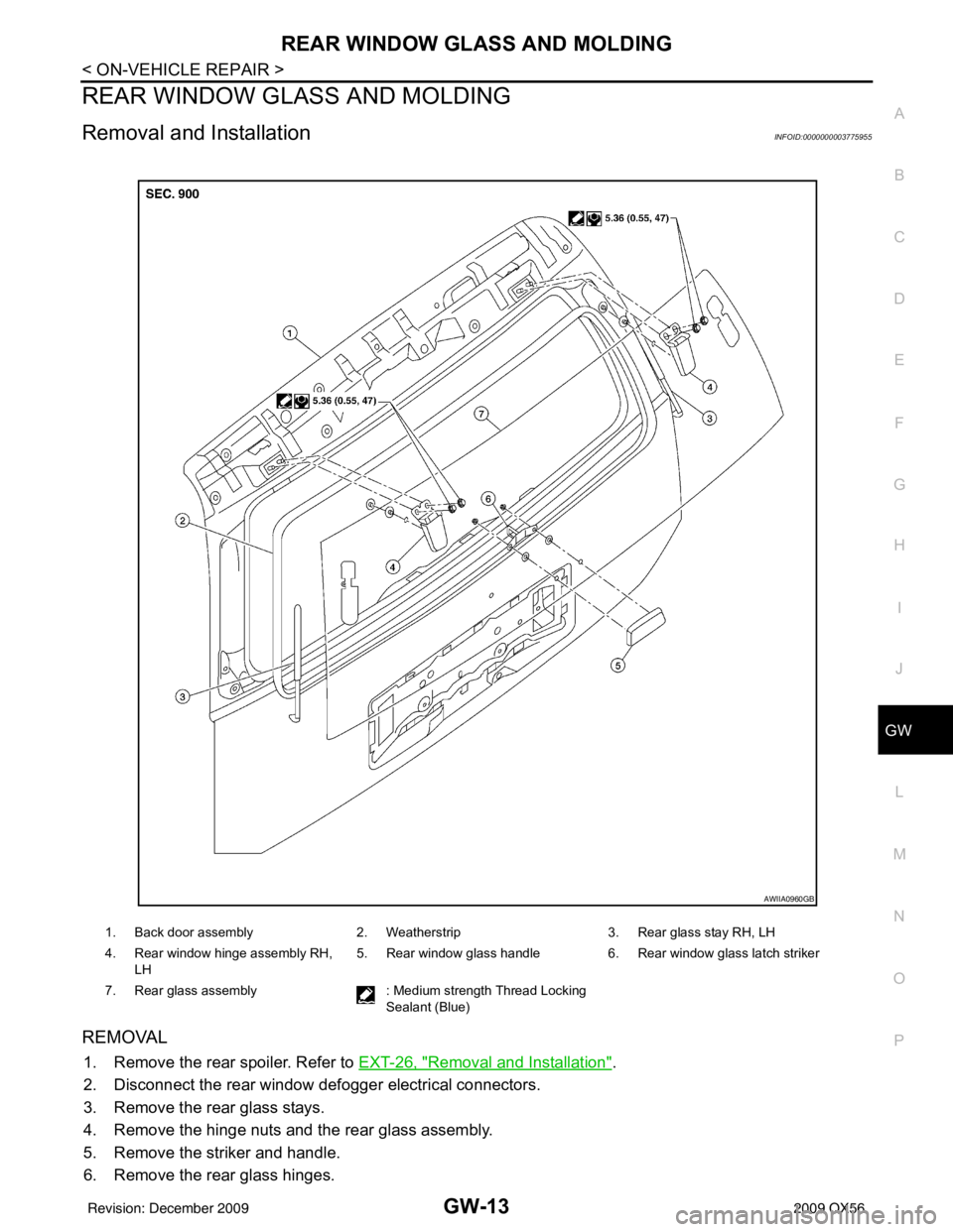
REMOVAL
1. Remove the rear spoiler. Refer to EXT-26, "Removal and Installation".
2. Disconnect the rear window def ogger electrical connectors.
3. Remove the rear glass stays.
4. Remove the hinge nuts and the rear glass assembly.
5. Remove the striker and handle.
6. Remove the rear glass hinges.
1. Back door assembly 2. Weatherstrip3. Rear glass stay RH, LH
4. Rear window hinge assembly RH, LH 5. Rear window glass handle
6. Rear window glass latch striker
7. Rear glass assembly : Medium strength Thread Locking
Sealant (Blue)
AWIIA0960GB
Revision: December 20092009 QX56
Page 2256 of 4171

GW-14
< ON-VEHICLE REPAIR >
REAR WINDOW GLASS AND MOLDING
INSTALLATION
Installation is in the reverse order of removal.
Rear Window Stay DisposalINFOID:0000000005864741
1. Fix window stay (1) using a vise (C).
2. Using hacksaw (A) slowly make two holes in the window stay, innumerical order as shown in the figure.
CAUTION:
• When cutting a hole on win dow stay, always cover a hack-
saw using a shop cloth (B) to avoid scattering metal frag-
ments or oil.
• Wear eye protection (safety glasses).
• Wear gloves.
JMKIA3336ZZ
A: 20 mm (0.787 in)
B: Cut in numerical order as
shown at the groove.
JMKIA3609ZZ
Revision: December 20092009 QX56
Page 2257 of 4171

FRONT DOOR GLASS AND REGULATORGW-15
< ON-VEHICLE REPAIR >
C
DE
F
G H
I
J
L
M A
B
GW
N
O P
FRONT DOOR GLASS AND REGULATOR
Removal and InstallationINFOID:0000000003775956
FRONT DOOR GLASS
Removal
1. Remove the front door finisher. Refer to INT-11, "Removal and Installation".
2. Position aside the vapor barrier.
3. Remove the hole cover over rear glass bolt.
4. Temporarily reconnect the power window switch.
5. Operate the power window main switch to raise/lo wer the door window until the glass bolts can be seen.
6. Remove the glass bolts.
7. While holding the front door glass, raise it at the rear end and pull the glass out of the sash toward the outside of the door.
Installation
Installation is in the reverse order of removal.
1. Door glass run 2. Door glass3. Front door glass regulator assembly
WIIA0941E
LIIA1687E
Glass bolts: 6.1 N·m (0.62 kg-m, 54 in-lb)
Revision: December 20092009 QX56
Page 2258 of 4171

GW-16
< ON-VEHICLE REPAIR >
FRONT DOOR GLASS AND REGULATOR
NOTE:
If any of the following work has been done, reset the power window motor limit switch.
• Removal and installation of the regulator assembly.
• Removal and installation of the power window motor from the regulator.
• Installation of a new glass window.
• Installation of a new glass run.
Check the label on the power window motor for the part number. If the power window motor part number
matches one of the following, the motor must be removed from the regulator and the limit switch reset using
the “INSTALLATION WITHOUT RESET SWITCH” procedure in “FRONT DOOR GLASS REGULATOR
ASSEMBLY”.
• 80730-ZT01A
• 80731-ZT01A
• 80730-ZM70B
• 80731-ZM70B
If the power window motor part number does not match one of the part numbers above, the limit switch can be
reset in the vehicle using the “INSTA LLATION WITH RESET SWITCH” procedure.
NOTE:
• The label can be checked with the power window motor in the vehicle by using a mirror.
• Some of the power window motors with the part num bers above may appear to have a reset switch, but it will
not reset the limit switch.
Fitting Inspection
• Check that the glass is securely fit into the glass run groove.
• Lower the glass slightly [approximately 10 to 20 mm (0 .39 to 0.79 in)] and check that the clearance to the
sash is parallel. If the clearance between the glass and sash is not parallel, loosen the regulator bolts, guide
rail bolts, and glass and guide rail bolts to correct the glass position.
FRONT DOOR GLASS REGULATOR
Removal
1. Remove the front door finisher. Refer to INT-11, "Removal and Installation".
2. Position the aside the vapor barrier.
3. Remove the hole cover over rear glass bolt.
4. Temporarily reconnect the power window switch.
5. Operate the power window main switch to raise/ lower the door window until the glass bolts can be seen.
6. Remove the glass bolts.
7. Raise the front door glass and hold it in place with suitable tool.
8. Disconnect the harness connector fr om the regulator assembly.
9. Remove the bolts and the regulator assembly.
Disassembly And Assembly
Remove the regulator motor from the regulator assembly.
Inspection After Removal
Check the regulator assembly for the following items. If a malfunc-
tion is detected, replace or grease it.
• Wire wear
• Regulator deformation
• Grease condition for each sliding part
The arrows in the figure show the application points of the body
grease.
SETTING AFTER INSTALLATION
Installation
If any of the following work has been done, reset the power window motor limit switch.
• Removal and installation of the regulator assembly.
LIIA0670E
Revision: December 20092009 QX56
Page 2259 of 4171

FRONT DOOR GLASS AND REGULATORGW-17
< ON-VEHICLE REPAIR >
C
DE
F
G H
I
J
L
M A
B
GW
N
O P
• Removal and installation of the power window motor from the regulator.
• Installation of a new glass window.
• Installation of a new glass run.
Check the label on the power window motor for the part number. If the power window motor part number
matches one of the following, the limit switch must be reset using the “INSTALLATION WITHOUT RESET
SWITCH” procedure.
• 80730-ZT01A
• 80731-ZT01A
• 80730-ZM70B
• 80731-ZM70B
If the power window motor part number does not match one of the part numbers above, the limit switch must
be reset using the “INSTALLATION WITH RESET SWITCH” procedure.
NOTE:
Some of the power window motors with the part num bers above may appear to have a reset switch, but it will
not reset the limit switch.
INSTALLATION WITHOUT RESET SWITCH - (Motors listed above)
Check the label on the power window motor for the pa rt number. If the power window motor part number does
not match one of the above, use the “INSTALLATION WITH RESET SWITCH” procedure.
NOTE:
Some of the power window motors may appear to have a re set switch, but it will not reset the limit switch.
1. Connect the door harness connector to the power window motor, and rotate the motor more than 5 turns
in the glass raising (up) direction.
2. Install the power window motor onto the regulator.
3. Install the regulator assembly into the door and secure regulator assembly with the nuts and bolt.
4. Install the glass into the door and align with the regulator, then install the glass bolts.
5. Raise the glass to the top position. CAUTION:
Do not operate the glass automatical ly to raise the glass to the top.
6. Reposition the vapor barrier.
7. Install the front door finisher panel. Refer to INT-11, "
Removal and Installation".
INSTALLATION WITH RESET SWITCH - (Motors not listed above)
1. Install the power window motor onto the regulator.
2. Install the regulator assembly into the door and secure regulator assembly with the nuts and bolt.
3. Connect the door harness connector to the power window motor.
4. Install the glass into the door and align with the regulator, then install the glass bolts.
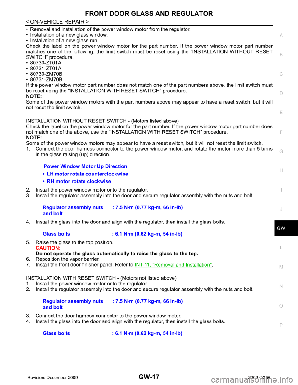
Power Window Motor Up Direction
• LH motor rotate counterclockwise
• RH motor rotate clockwise
Regulator assembly nuts
and bolt : 7.5 N·m (0.77 kg-m, 66 in-lb)
Glass bolts : 6.1 N·m (0.62 kg-m, 54 in-lb)
Regulator assembly nuts
and bolt : 7.5 N·m (0.77 kg-m, 66 in-lb)
Glass bolts : 6.1 N·m (0.62 kg-m, 54 in-lb)
Revision: December 20092009 QX56
Page 2260 of 4171

GW-18
< ON-VEHICLE REPAIR >
FRONT DOOR GLASS AND REGULATOR
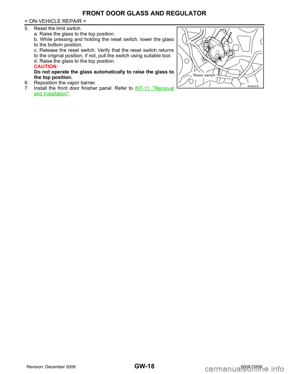
5. Reset the limit switch.a. Raise the glass to the top position.
b. While pressing and holding the reset switch, lower the glass
to the bottom position.
c. Release the reset switch. Verify that the reset switch returns
to the original position, if not, pull the switch using suitable tool.
d. Raise the glass to the top position.
CAUTION:
Do not operate the glass automatically to raise the glass to
the top position.
6. Reposition the vapor barrier.
7. Install the front door finisher panel. Refer to INT-11, "
Removal
and Installation".
SIIA0347E
Revision: December 20092009 QX56