lock INFINITI QX56 2009 Factory Service Manual
[x] Cancel search | Manufacturer: INFINITI, Model Year: 2009, Model line: QX56, Model: INFINITI QX56 2009Pages: 4171, PDF Size: 84.65 MB
Page 1920 of 4171
ENGINE UNITEM-97
< DISASSEMBLY AND ASSEMBLY >
C
DE
F
G H
I
J
K L
M A
EM
NP
O
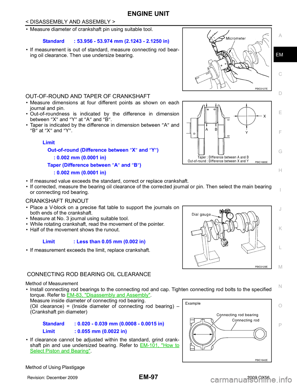
• Measure diameter of crankshaft pin using suitable tool.
• If measurement is out of standard, measure connecting rod bear-
ing oil clearance. Then use undersize bearing.
OUT-OF-ROUND AND TAPER OF CRANKSHAFT
• Measure dimensions at four di fferent points as shown on each
journal and pin.
• Out-of-roundness is indicated by the difference in dimension
between ″X″ and ″Y″ at ″A″ and ″B″ .
• Taper is indicated by the difference in dimension between ″A ″ and
″ B″ at ″X ″ and ″Y″ .
• If measured value exceeds the standard, correct or replace crankshaft.
• If corrected, measure the bearing oil clearance of the corrected journal or pin. Then select the main bearing or connecting rod bearing.
CRANKSHAFT RUNOUT
• Place a V-block on a precise flat table to support the journals onboth ends of the crankshaft.
• Measure at No. 3 journal using suitable tool.
• While rotating crankshaft, read the movement of the pointer.
• Half of the movement shows the runout.
• If measurement exceeds the limit, replace crankshaft.
CONNECTING ROD BEARING OIL CLEARANCE
Method of Measurement
• Install connecting rod bearings to the connecting rod and cap. Tighten connecting rod bolts to the specified
torque. Refer to EM-83, "
Disassembly and Assembly".
Measure inside diameter of connecting rod bearing.
(Oil clearance) = (Inside diameter of connecting rod bearing) –
(Crankshaft pin diameter)
• If clearance cannot be adjusted wit hin the standard, grind crank-
shaft pin and use undersized bearing. Refer to EM-101, "
How to
Select Piston and Bearing".
Method of Using Plastigage
Standard : 53.956 - 53.974 mm (2.1243 - 2.1250 in)
PBIC0127E
Limit
Out-of-round (Difference between ″X ″ and ″ Y″)
: 0.002 mm (0.0001 in)
Taper (Difference between ″ A″ and ″B ″)
: 0.002 mm (0.0001 in)
PBIC1685E
Limit : Less than 0.05 mm (0.002 in)
PBIC0129E
Standard : 0.020 - 0.039 mm (0.0008 - 0.0015 in)
Limit : 0.055 mm (0.0022 in)
PBIC1642E
Revision: December 20092009 QX56
Page 1921 of 4171
EM-98
< DISASSEMBLY AND ASSEMBLY >
ENGINE UNIT
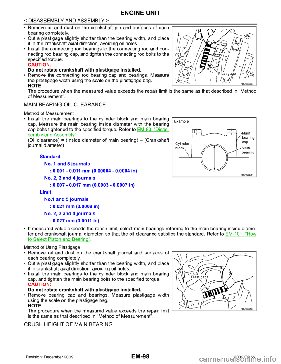
• Remove oil and dust on the crankshaft pin and surfaces of eachbearing completely.
• Cut a plastigage slightly shorter than the bearing width, and place
it in the crankshaft axial direction, avoiding oil holes.
• Install the connecting rod beari ngs to the connecting rod and con-
necting rod bearing cap, and tighten the connecting rod bolts to the
specified torque.
CAUTION:
Do not rotate crankshaft with plastigage installed.
• Remove the connecting rod bear ing cap and bearings. Measure
the plastigage width using the scale on the plastigage bag.
NOTE:
The procedure when the measured value exceeds the repair limit is the same as that described in “Method
of Measurement”.
MAIN BEARING OIL CLEARANCE
Method of Measurement
• Install the main bearings to the cylinder block and main bearing cap. Measure the main bearing inside diameter with the bearing
cap bolts tightened to the specified torque. Refer to EM-83, "
Disas-
sembly and Assembly".
(Oil clearance) = (Inside diameter of main bearing) – (Crankshaft
journal diameter)
• If measured value exceeds the repair limit, select main bearings referring to the main bearing inside diame-
ter and crankshaft journal diameter, so that the oil clearance satisfies the standard. Refer to EM-101, "
How
to Select Piston and Bearing".
Method of Using Plastigage
• Remove oil and dust on the crankshaft journal and surfaces of
each bearing completely.
• Cut a plastigage slightly shorter than the bearing width, and place it in crankshaft axial direction, avoiding oil holes.
• Install the main bearings to the cylinder block and main bearing cap, and tighten the main bearing bolts to the specified torque.
CAUTION:
Do not rotate crankshaft with plastigage installed.
• Remove bearing cap and bearings. Measure plastigage width using the scale on the plastigage bag.
NOTE:
The procedure when the measured value exceeds the repair limit
is the same as that descri bed in “Method of Measurement”.
CRUSH HEIGHT OF MAIN BEARING
KBIA2550E
Standard:
No. 1 and 5 journals : 0.001 - 0.011 mm (0.00004 - 0.0004 in)
No. 2, 3 and 4 journals : 0.007 - 0.017 mm (0.0003 - 0.0007 in)
Limit: No.1 and 5 journals : 0.021 mm (0.0008 in)
No. 2, 3 and 4 journals : 0.027 mm (0.0011 in)
PBIC1644E
KBIA2551E
Revision: December 20092009 QX56
Page 1924 of 4171
HOW TO SELECT PISTON AND BEARINGEM-101
< DISASSEMBLY AND ASSEMBLY >
C
DE
F
G H
I
J
K L
M A
EM
NP
O
HOW TO SELECT PISTON AND BEARING
How to Select Piston and BearingINFOID:0000000005885904
DESCRIPTION
*For the service parts, the grade for fitting cannot be selected between a piston pin and a connecting rod.
(Only 0 grade is available.) The information at the sh
ipment from the plant is described as a reference.
• The identification grade stamped on each part is the grade for the dimension measured in new condition.
This grade cannot apply to reused parts.
• For reused or repaired parts, measure the dimens ion accurately. Determine the grade by comparing the
measurement with the values of each selection table.
• For details of the measurement method of each part , the reuse standards, and the selection method of the
selective fitting parts, follow the applicable procedures.
HOW TO SELECT PISTON
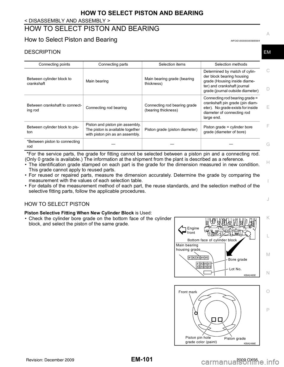
Piston Selective Fitting When New Cylinder Block is Used:
• Check the cylinder bore grade on the bottom face of the cylinder
block, and select the piston of the same grade.
Connecting points Connecting parts Selection itemsSelection methods
Between cylinder block to
crankshaft Main bearing Main bearing grade (bearing
thickness)Determined by match of cylin-
der block bearing housing
grade (Housing inside diame-
ter) and crankshaft journal
grade (journal outside diameter)
Between crankshaft to connect-
ing rod Connecting rod bearing Connecting rod bearing grade
(bearing thickness)Connecting rod bearing grade =
crankshaft pin grade (pin diam-
eter). No grade exists for inside
diameter of connecting rod
large end.
Between cylinder block to pis-
ton Piston and piston pin assembly.
The piston is available together
with piston pin as an assembly.
Piston grade (piston diameter)
Piston grade = cylinder bore
grade (diameter of bore)
*Between piston to connecting
rod ———
KBIA2495E
KBIA2496E
Revision: December 20092009 QX56
Page 1925 of 4171
EM-102
< DISASSEMBLY AND ASSEMBLY >
HOW TO SELECT PISTON AND BEARING
When Cylinder Block is Reused
1. Measure cylinder block bore diameter.
2. Determine the bore grade by comparing the measurement with the values under the “Cylinder bore diam-
eter” of the piston selection table.
Piston Selection Table
Unit: mm (in)
NOTE:
• The piston is available together with piston pin as an assembly.
• The piston pin (piston pin bore) grade is provided only for the parts installed at the plant. For service parts, no grades can be selected (only 0 grade is available).
HOW TO SELECT CONNECTING ROD BEARING
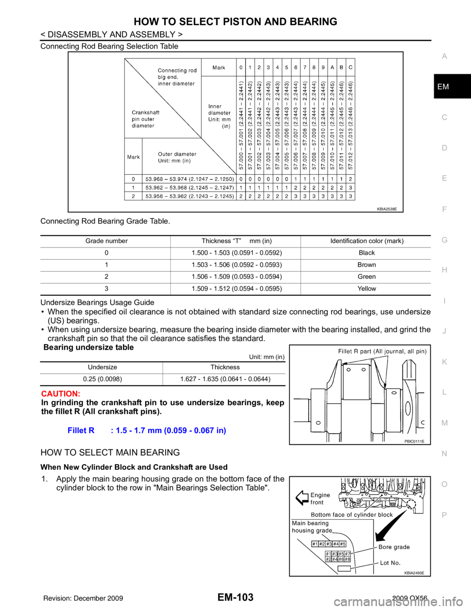
When New Connecting Rod and Crankshaft are Used
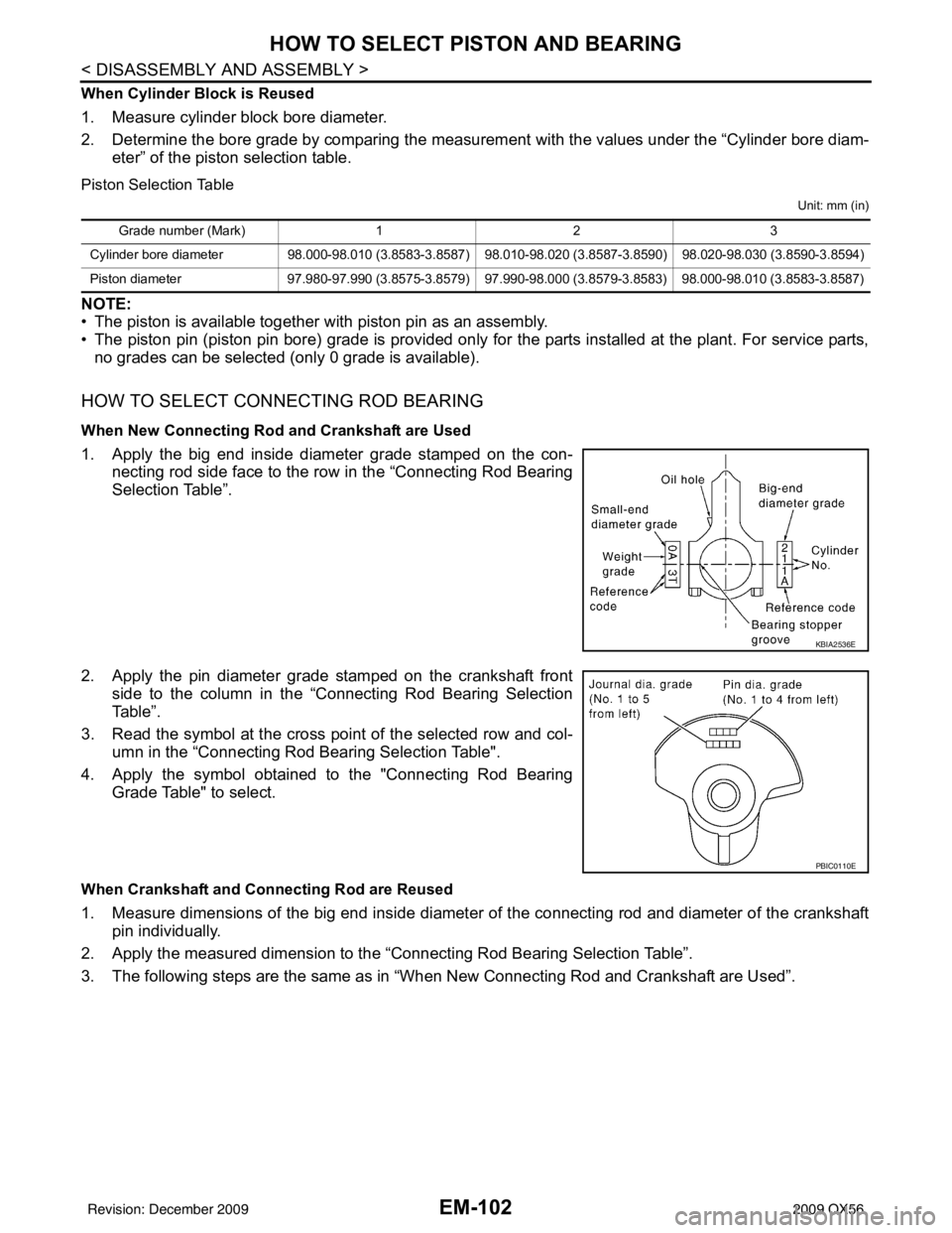
1. Apply the big end inside diameter grade stamped on the con-
necting rod side face to the row in the “Connecting Rod Bearing
Selection Table”.
2. Apply the pin diameter grade stamped on the crankshaft front side to the column in the “Connecting Rod Bearing Selection
Table”.
3. Read the symbol at the cross point of the selected row and col-
umn in the “Connecting Rod Bearing Selection Table".
4. Apply the symbol obtained to the "Connecting Rod Bearing Grade Table" to select.
When Crankshaft and Connecting Rod are Reused
1. Measure dimensions of the big end inside diameter of the connecting rod and diameter of the crankshaftpin individually.
2. Apply the measured dimension to the “Connecting Rod Bearing Selection Table”.
3. The following steps are the same as in “When New Connecting Rod and Crankshaft are Used”.
Grade number (Mark) 12 3
Cylinder bore diameter 98.000-98.010 (3.8583-3.8587) 98.010-98.020 (3.8587-3.8590) 98.020-98.030 (3.8590-3.8594)
Piston diameter 97.980-97.990 (3.8575-3.8579) 97.990-98.000 (3.8579-3.8583) 98.000-98.010 (3.8583-3.8587)
KBIA2536E
PBIC0110E
Revision: December 20092009 QX56
Page 1926 of 4171
HOW TO SELECT PISTON AND BEARINGEM-103
< DISASSEMBLY AND ASSEMBLY >
C
DE
F
G H
I
J
K L
M A
EM
NP
O
Connecting Rod Bearing Selection Table
Connecting Rod Bearing Grade Table.
Undersize Bearings Usage Guide
• When the specified oil clearance is not obtained with standard size connecting rod bearings, use undersize
(US) bearings.
• When using undersize bearing, measure the bearing inside diameter with the bearing installed, and grind the
crankshaft pin so that the oil clearance satisfies the standard.
Bearing undersize table
Unit: mm (in)
CAUTION:
In grinding the crankshaft pin to use undersize bearings, keep
the fillet R (All crankshaft pins).
HOW TO SELECT MAIN BEARING
When New Cylinder Block and Crankshaft are Used
1. Apply the main bearing housing grade on the bottom face of the cylinder block to the row in "Main Bearings Selection Table".
KBIA2538E
Grade number Thickness “T” mm (in) Identification color (mark)
0 1.500 - 1.503 (0.0591 - 0.0592) Black
1 1.503 - 1.506 (0.0592 - 0.0593) Brown
2 1.506 - 1.509 (0.0593 - 0.0594) Green
3 1.509 - 1.512 (0.0594 - 0.0595) Yellow
UndersizeThickness
0.25 (0.0098) 1.627 - 1.635 (0.0641 - 0.0644)
Fillet R : 1.5 - 1.7 mm (0.059 - 0.067 in)
PBIC0111E
KBIA2495E
Revision: December 20092009 QX56
Page 1927 of 4171
EM-104
< DISASSEMBLY AND ASSEMBLY >
HOW TO SELECT PISTON AND BEARING
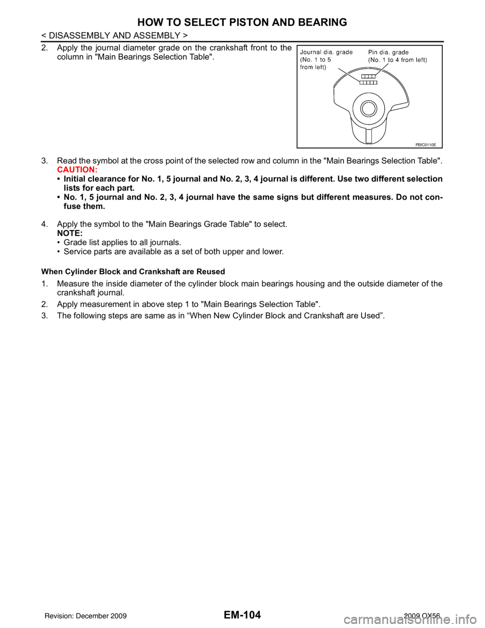
2. Apply the journal diameter grade on the crankshaft front to thecolumn in "Main Bearings Selection Table".
3. Read the symbol at the cross point of the selected row and column in the "Main Bearings Selection Table".
CAUTION:
• Initial clearance for No. 1, 5 journal and No. 2, 3, 4 journal is different. Use two different selection
lists for each part.
• No. 1, 5 journal and No. 2, 3, 4 journal have the same signs but different measures. Do not con-
fuse them.
4. Apply the symbol to the "Main Bearings Grade Table" to select. NOTE:
• Grade list applies to all journals.
• Service parts are available as a set of both upper and lower.
When Cylinder Block and Crankshaft are Reused
1. Measure the inside diameter of the cylinder block main bearings housing and the outside diameter of the
crankshaft journal.
2. Apply measurement in above step 1 to "Main Bearings Selection Table".
3. The following steps are same as in “When New Cylinder Block and Crankshaft are Used”.
PBIC0110E
Revision: December 20092009 QX56
Page 1936 of 4171
SERVICE DATA AND SPECIFICATIONS (SDS)EM-113
< SERVICE DATA AND SPECIFICATIONS (SDS)
C
DE
F
G H
I
J
K L
M A
EM
NP
O
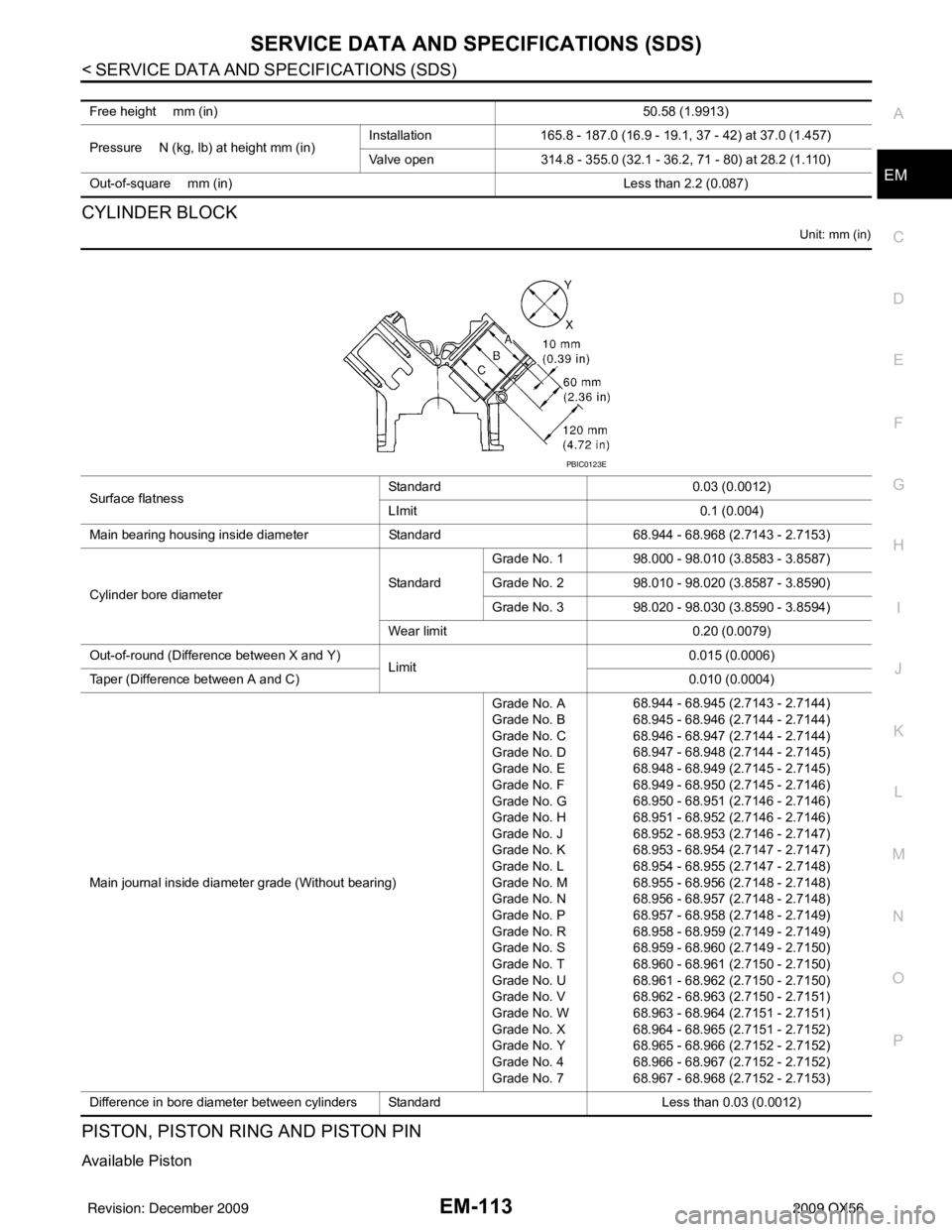
CYLINDER BLOCK
Unit: mm (in)
PISTON, PISTON RING AND PISTON PIN
Available Piston
Free height mm (in)
50.58 (1.9913)
Pressure N (kg, lb) at height mm (in) Installation
165.8 - 187.0 (16.9 - 19.1, 37 - 42) at 37.0 (1.457)
Valve open 314.8 - 355.0 (32.1 - 36.2, 71 - 80) at 28.2 (1.110)
Out-of-square mm (in) Less than 2.2 (0.087)
Surface flatnessStandard
0.03 (0.0012)
LImit 0.1 (0.004)
Main bearing housing inside diameter Standard68.944 - 68.968 (2.7143 - 2.7153)
Cylinder bore diameter StandardGrade No. 1
98.000 - 98.010 (3.8583 - 3.8587)
Grade No. 2 98.010 - 98.020 (3.8587 - 3.8590)
Grade No. 3 98.020 - 98.030 (3.8590 - 3.8594)
Wear limit 0.20 (0.0079)
Out-of-round (Difference between X and Y) Limit 0.015 (0.0006)
Taper (Difference between A and C) 0.010 (0.0004)
Main journal inside diameter grade (Without bearing) Grade No. A
Grade No. B
Grade No. C
Grade No. D
Grade No. E
Grade No. F
Grade No. G
Grade No. H
Grade No. J
Grade No. K
Grade No. L
Grade No. M
Grade No. N
Grade No. P
Grade No. R
Grade No. S
Grade No. T
Grade No. U
Grade No. V
Grade No. W
Grade No. X
Grade No. Y
Grade No. 4
Grade No. 768.944 - 68.945 (2.7143 - 2.7144)
68.945 - 68.946 (2.7144 - 2.7144)
68.946 - 68.947 (2.7144 - 2.7144)
68.947 - 68.948 (2.7144 - 2.7145)
68.948 - 68.949 (2.7145 - 2.7145)
68.949 - 68.950 (2.7145 - 2.7146)
68.950 - 68.951 (2.7146 - 2.7146)
68.951 - 68.952 (2.7146 - 2.7146)
68.952 - 68.953 (2.7146 - 2.7147)
68.953 - 68.954 (2.7147 - 2.7147)
68.954 - 68.955 (2.7147 - 2.7148)
68.955 - 68.956 (2.7148 - 2.7148)
68.956 - 68.957 (2.7148 - 2.7148)
68.957 - 68.958 (2.7148 - 2.7149)
68.958 - 68.959 (2.7149 - 2.7149)
68.959 - 68.960 (2.7149 - 2.7150)
68.960 - 68.961 (2.7150 - 2.7150)
68.961 - 68.962 (2.7150 - 2.7150)
68.962 - 68.963 (2.7150 - 2.7151)
68.963 - 68.964 (2.7151 - 2.7151)
68.964 - 68.965 (2.7151 - 2.7152)
68.965 - 68.966 (2.7152 - 2.7152)
68.966 - 68.967 (2.7152 - 2.7152)
68.967 - 68.968 (2.7152 - 2.7153)
Difference in bore diameter between cylinders Standard Less than 0.03 (0.0012)
PBIC0123E
Revision: December 20092009 QX56
Page 1943 of 4171
EX-2
< PRECAUTION >
PRECAUTIONS
PRECAUTION
PRECAUTIONS
Precaution for Supplemental Restraint System (SRS) "AIR BAG" and "SEAT BELT
PRE-TENSIONER"
INFOID:0000000005851832
The Supplemental Restraint System such as “A IR BAG” and “SEAT BELT PRE-TENSIONER”, used along
with a front seat belt, helps to reduce the risk or severity of injury to the driver and front passenger for certain
types of collision. This system includes seat belt switch inputs and dual stage front air bag modules. The SRS
system uses the seat belt switches to determine the front air bag deployment, and may only deploy one front
air bag, depending on the severity of a collision and w hether the front occupants are belted or unbelted.
Information necessary to service the system safely is included in the SR and SB section of this Service Man-
ual.
WARNING:
• To avoid rendering the SRS inopera tive, which could increase the risk of personal injury or death in
the event of a collision which would result in air bag inflation, all maintenance must be performed by
an authorized NISSAN/INFINITI dealer.
• Improper maintenance, including in correct removal and installation of the SRS, can lead to personal
injury caused by unintent ional activation of the system. For re moval of Spiral Cable and Air Bag
Module, see the SR section.
• Do not use electrical test equipmen t on any circuit related to the SRS unless instructed to in this
Service Manual. SRS wiring harn esses can be identified by yellow and/or orange harnesses or har-
ness connectors.
PRECAUTIONS WHEN USING POWER TOOLS (AIR OR ELECTRIC) AND HAMMERS
WARNING:
• When working near the Airbag Diagnosis Sensor Unit or other Airbag System sensors with the Igni-
tion ON or engine running, DO NOT use air or electri c power tools or strike near the sensor(s) with a
hammer. Heavy vibration could activate the sensor( s) and deploy the air bag(s), possibly causing
serious injury.
• When using air or electric power tools or hammers , always switch the Ignition OFF, disconnect the
battery, and wait at least 3 minu tes before performing any service.
Precaution Necessary for Steering W heel Rotation After Battery Disconnect
INFOID:0000000005851833
NOTE:
• This Procedure is applied only to models with Intelligent Key system and NATS (NISSAN ANTI-THEFT SYS-
TEM).
• Remove and install all control units after disconnecting both battery cables with the ignition knob in the
″LOCK ″ position.
• Always use CONSULT-III to perform self-diagnosis as a part of each function inspection after finishing work.
If DTC is detected, perform trouble diagnosis according to self-diagnostic results.
For models equipped with the Intelligent Key system and NATS, an electrically controlled steering lock mech-
anism is adopted on the key cylinder.
For this reason, if the battery is disconnected or if the battery is discharged, the steering wheel will lock and
steering wheel rotation will become impossible.
If steering wheel rotation is required when battery pow er is interrupted, follow the procedure below before
starting the repair operation.
OPERATION PROCEDURE
1. Connect both battery cables. NOTE:
Supply power using jumper cables if battery is discharged.
2. Use the Intelligent Key or mechanical key to turn the ignition switch to the ″ACC ″ position. At this time, the
steering lock will be released.
3. Disconnect both battery cables. The steering lock will remain released and the steering wheel can be rotated.
4. Perform the necessary repair operation.
Revision: December 20092009 QX56
Page 1944 of 4171
PRECAUTIONSEX-3
< PRECAUTION >
C
DE
F
G H
I
J
K L
M A
EX
NP
O
5. When the repair work is completed, return the ignition switch to the
″LOCK ″ position before connecting
the battery cables. (At this time, the steering lock mechanism will engage.)
6. Perform a self-diagnosis check of al l control units using CONSULT-III.
Revision: December 20092009 QX56
Page 1976 of 4171
![INFINITI QX56 2009 Factory Service Manual EXL-28
< FUNCTION DIAGNOSIS >
DIAGNOSIS SYSTEM (IPDM E/R)
ACTIVE TEST
Te s t i t e m
Monitor Item[Unit] MAIN SIG-
NALS Description
MOTOR FAN REQ
[1/2/3/4] ×Displays the status of the cooling fan spe INFINITI QX56 2009 Factory Service Manual EXL-28
< FUNCTION DIAGNOSIS >
DIAGNOSIS SYSTEM (IPDM E/R)
ACTIVE TEST
Te s t i t e m
Monitor Item[Unit] MAIN SIG-
NALS Description
MOTOR FAN REQ
[1/2/3/4] ×Displays the status of the cooling fan spe](/img/42/57031/w960_57031-1975.png)
EXL-28
< FUNCTION DIAGNOSIS >
DIAGNOSIS SYSTEM (IPDM E/R)
ACTIVE TEST
Te s t i t e m
Monitor Item[Unit] MAIN SIG-
NALS Description
MOTOR FAN REQ
[1/2/3/4] ×Displays the status of the cooling fan speed request signal received from ECM via
CAN communication.
A/C COMP REQ
[OFF/ON] ×Displays the status of the A/C request signal received from AV control unit via
CAN communication.
TA I L & C L R R E Q
[OFF/ON] ×
Displays the status of the position light request signal received from BCM via CAN
communication.
HL LO REQ
[OFF/ON] ×Displays the status of the low beam request signal received from BCM via CAN
communication.
HL HI REQ
[OFF/ON] ×Displays the status of the high beam request signal received from BCM via CAN
communication.
FR FOG REQ
[OFF/ON] ×
Displays the status of the front fog lamp request signal received from BCM via
CAN communication.
HL WASHER REQ
[OFF/ON] NOTE:
This item is displayed, but cannot be monitored.
FR WIP REQ
[STOP/1LOW/LOW/HI] ×Displays the status of the front wiper request signal received from BCM via CAN
communication.
WIP AUTO STOP
[STOP P/ACT P] ×
Displays the status of the front wiper auto stop signal judged by IPDM E/R.
WIP PROT
[OFF/Block] ×
Displays the status of the front wiper fail-safe operation judged by IPDM E/R.
ST RLY REQ
[OFF/ON] Displays the status of the starter request signal received from ECM via CAN com-
munication.
IGN RLY
[OFF/ON] ×
Displays the status of the ignition relay judged by IPDM E/R.
RR DEF REQ
[OFF/ON] ×Displays the status of the rear defogger request signal received from AV control
unit via CAN communication.
OIL P SW
[OPEN/CLOSE] Displays the status of the oil pressure switch judged by IPDM E/R.
DTRL REQ
[OFF] Displays the status of the daytime light request signal received from BCM via CAN
communication.
HOOD SW
[OPEN/CLOSE] Displays the status of the hood switch judged by IPDM E/R.
THFT HRN REQ
[OFF/ON] Displays the status of the theft warning horn request signal received from BCM
via CAN communication.
HORN CHIRP
[OFF/ON] Displays the status of the horn reminder signal received from BCM via CAN com-
munication.
Test item
Operation Description
REAR DEFOGGER OFF
OFF
ON Operates rear window defogger relay.
FRONT WIPER OFF
OFF
LO Operates the front wiper relay.
HI Operates the front wiper relay and front wiper high relay.
MOTOR FAN 1O
FF
2O FF
3 Operates the cooling fan relay.
4 Operates the cooling fan relay.
Revision: December 20092009 QX56