200 INFINITI QX56 2009 Factory Service Manual
[x] Cancel search | Manufacturer: INFINITI, Model Year: 2009, Model line: QX56, Model: INFINITI QX56 2009Pages: 4171, PDF Size: 84.65 MB
Page 3854 of 4171
TM-206
< ON-VEHICLE REPAIR >
CONTROL VALVE WITH TCM
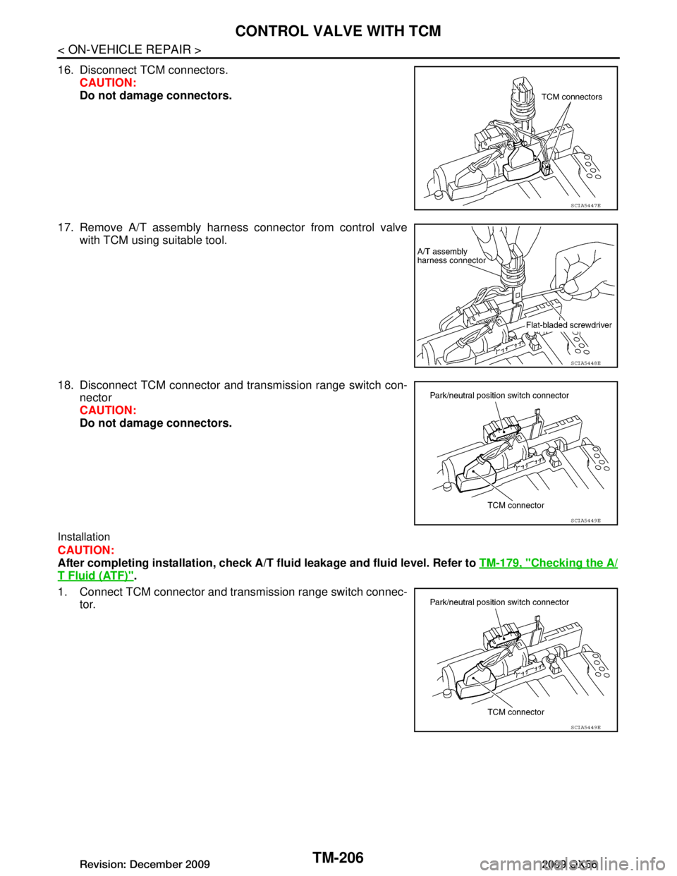
16. Disconnect TCM connectors.CAUTION:
Do not damage connectors.
17. Remove A/T assembly harness connector from control valve with TCM using suitable tool.
18. Disconnect TCM connector and transmission range switch con- nector
CAUTION:
Do not damage connectors.
Installation
CAUTION:
After completing installation, check A/T fluid leakage and fluid level. Refer to TM-179, "Checking the A/
T Fluid (ATF)".
1. Connect TCM connector and trans mission range switch connec-
tor.
SCIA5447E
SCIA5448E
SCIA5449E
SCIA5449E
Revision: December 20092009 QX56
Page 3855 of 4171
CONTROL VALVE WITH TCMTM-207
< ON-VEHICLE REPAIR >
CEF
G H
I
J
K L
M A
B
TM
N
O P
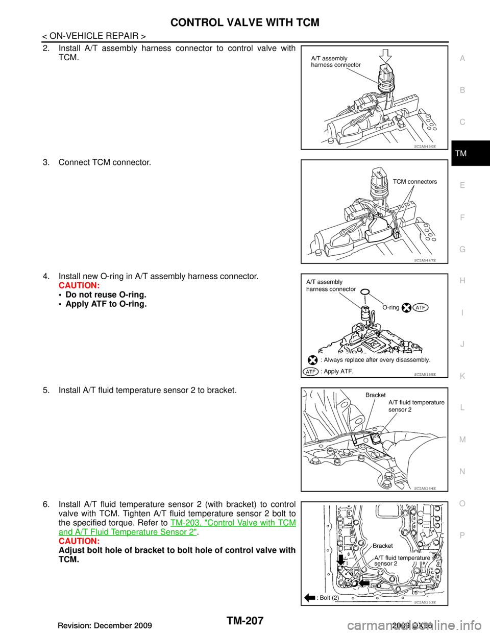
2. Install A/T assembly harness connector to control valve with TCM.
3. Connect TCM connector.
4. Install new O-ring in A/T assembly harness connector. CAUTION:
Do not reuse O-ring.
Apply ATF to O-ring.
5. Install A/T fluid temperature sensor 2 to bracket.
6. Install A/T fluid temperature sensor 2 (with bracket) to control valve with TCM. Tighten A/T flui d temperature sensor 2 bolt to
the specified torque. Refer to TM-203, "Control Valve with TCM
and A/T Fluid Temperature Sensor 2".
CAUTION:
Adjust bolt hole of bracket to bolt hole of control valve with
TCM.
SCIA5450E
SCIA5447E
SCIA5155E
SCIA5264E
SCIA5253E
Revision: December 20092009 QX56
Page 3856 of 4171
TM-208
< ON-VEHICLE REPAIR >
CONTROL VALVE WITH TCM
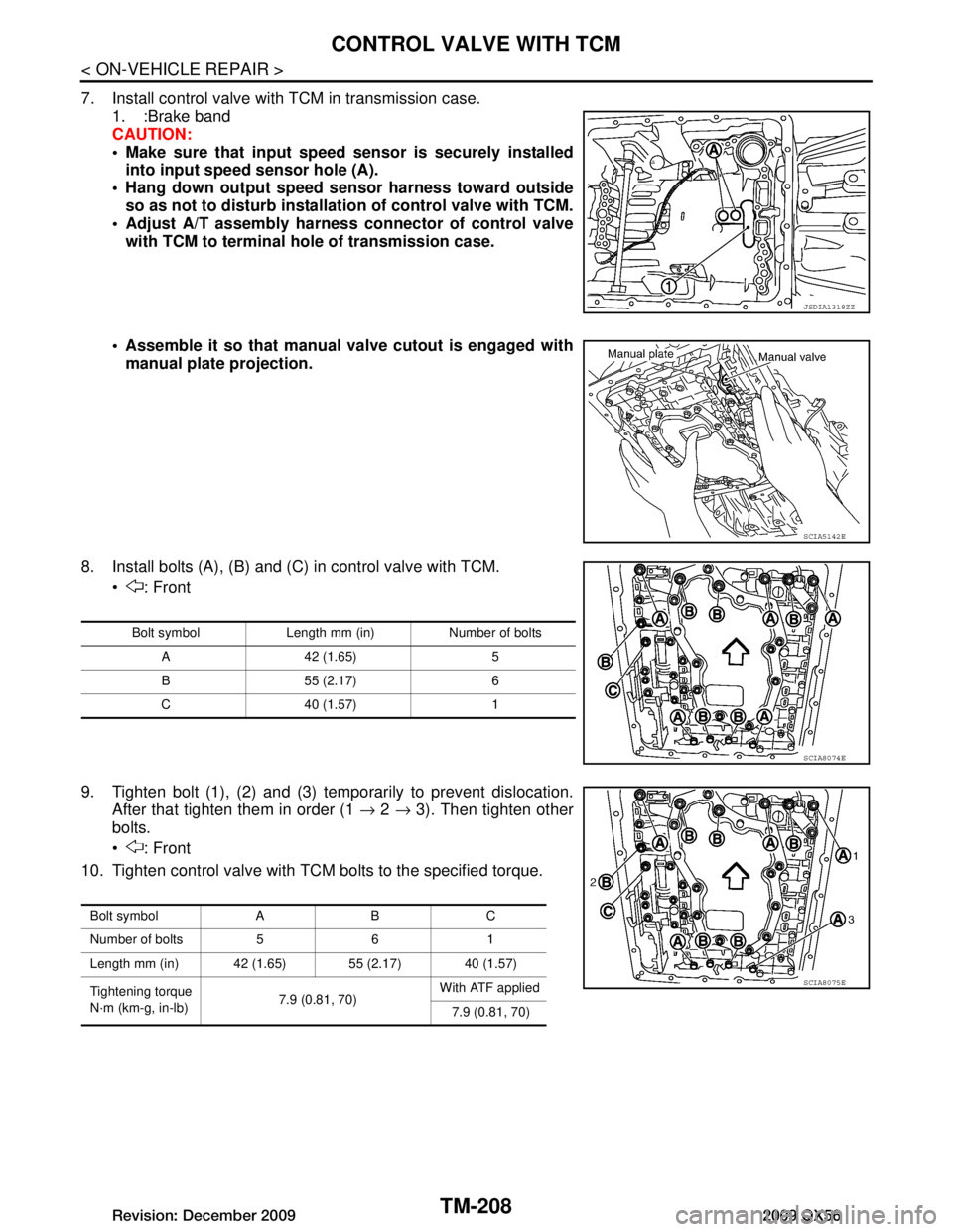
7. Install control valve with TCM in transmission case.1. :Brake band
CAUTION:
Make sure that input speed sensor is securely installed
into input speed sensor hole (A).
Hang down output speed sen sor harness toward outside
so as not to disturb installati on of control valve with TCM.
Adjust A/T assembly harness co nnector of control valve
with TCM to terminal hole of transmission case.
Assemble it so that manual valve cutout is engaged with manual plate projection.
8. Install bolts (A), (B) and (C) in control valve with TCM. : Front
9. Tighten bolt (1), (2) and (3) temporarily to prevent dislocation. After that tighten them in order (1 → 2 → 3). Then tighten other
bolts.
: Front
10. Tighten control valve with TCM bolts to the specified torque.
JSDIA1318ZZ
SCIA5142E
Bolt symbol Length mm (in) Number of bolts
A 42 (1.65) 5
B 55 (2.17) 6
C 40 (1.57) 1
SCIA8074E
Bolt symbol A B C
Number of bolts 5 6 1
Length mm (in) 42 (1.65) 55 (2.17) 40 (1.57)
Tightening torque
N·m (km-g, in-lb) 7.9 (0.81, 70)With ATF applied
7.9 (0.81, 70)
SCIA8075E
Revision: December 20092009 QX56
Page 3857 of 4171
CONTROL VALVE WITH TCMTM-209
< ON-VEHICLE REPAIR >
CEF
G H
I
J
K L
M A
B
TM
N
O P
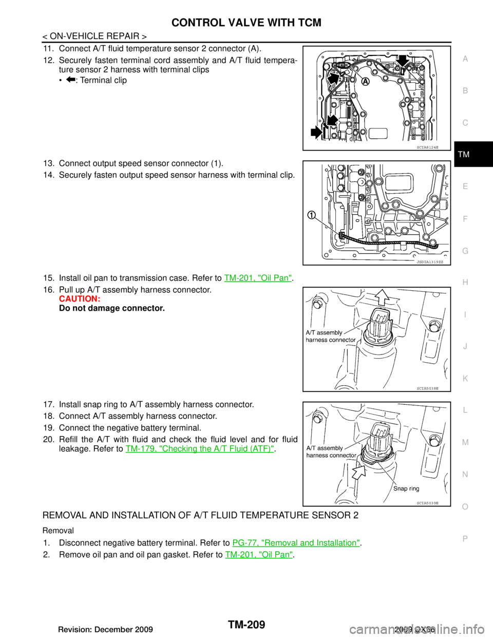
11. Connect A/T fluid temperature sensor 2 connector (A).
12. Securely fasten terminal cord assembly and A/T fluid tempera- ture sensor 2 harness with terminal clips
: Terminal clip
13. Connect output speed sensor connector (1).
14. Securely fasten output speed sensor harness with terminal clip.
15. Install oil pan to transmission case. Refer to TM-201, "Oil Pan"
.
16. Pull up A/T assembly harness connector. CAUTION:
Do not damage connector.
17. Install snap ring to A/T assembly harness connector.
18. Connect A/T assembly harness connector.
19. Connect the negative battery terminal.
20. Refill the A/T with fluid and check the fluid level and for fluid leakage. Refer to TM-179, "Checking the A/T Fluid (ATF)"
.
REMOVAL AND INSTALLATION OF A/ T FLUID TEMPERATURE SENSOR 2
Removal
1. Disconnect negative battery terminal. Refer to PG-77, "Removal and Installation".
2. Remove oil pan and oil pan gasket. Refer to TM-201, "Oil Pan"
.
SCIA8124E
JSDIA1319ZZ
SCIA5038E
SCIA5039E
Revision: December 20092009 QX56
Page 3858 of 4171
TM-210
< ON-VEHICLE REPAIR >
CONTROL VALVE WITH TCM
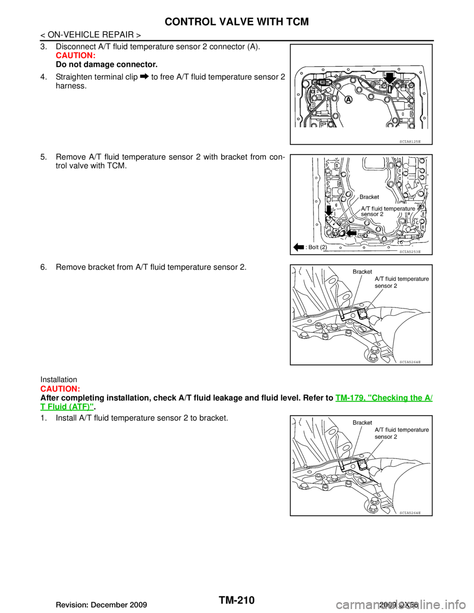
3. Disconnect A/T fluid temperature sensor 2 connector (A).
CAUTION:
Do not damage connector.
4. Straighten terminal clip to free A/T fluid temperature sensor 2 harness.
5. Remove A/T fluid temperature sensor 2 with bracket from con- trol valve with TCM.
6. Remove bracket from A/T fluid temperature sensor 2.
Installation
CAUTION:
After completing installation, check A/T fluid leakage and fluid level. Refer to TM-179, "Checking the A/
T Fluid (ATF)".
1. Install A/T fluid temperature sensor 2 to bracket.
SCIA8125E
SCIA5253E
SCIA5264E
SCIA5264E
Revision: December 20092009 QX56
Page 3859 of 4171
CONTROL VALVE WITH TCMTM-211
< ON-VEHICLE REPAIR >
CEF
G H
I
J
K L
M A
B
TM
N
O P
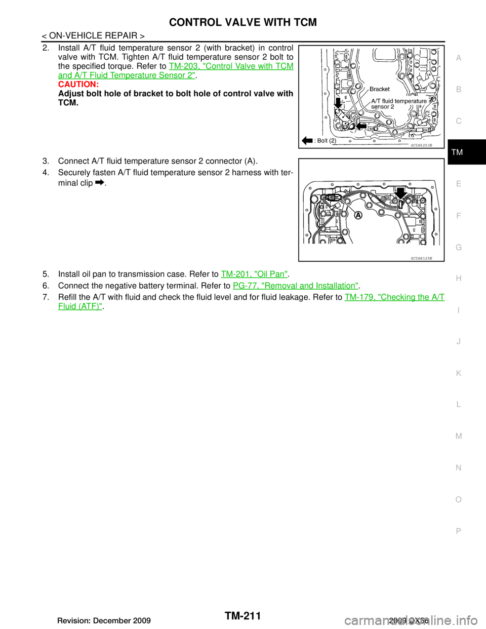
2. Install A/T fluid temperature sens or 2 (with bracket) in control
valve with TCM. Tighten A/T flui d temperature sensor 2 bolt to
the specified torque. Refer to TM-203, "Control Valve with TCM
and A/T Fluid Temperature Sensor 2".
CAUTION:
Adjust bolt hole of bracket to bolt hole of control valve with
TCM.
3. Connect A/T fluid temperature sensor 2 connector (A).
4. Securely fasten A/T fluid temperature sensor 2 harness with ter- minal clip .
5. Install oil pan to transmission case. Refer to TM-201, "Oil Pan"
.
6. Connect the negative battery terminal. Refer to PG-77, "Removal and Installation"
.
7. Refill the A/T with fluid and check the fluid level and for fluid leakage. Refer to TM-179, "Checking the A/T
Fluid (ATF)".
SCIA5253E
SCIA8125E
Revision: December 20092009 QX56
Page 3860 of 4171
TM-212
< ON-VEHICLE REPAIR >
REAR OIL SEAL
REAR OIL SEAL
Rear Oil SealINFOID:0000000004187482
REMOVAL AND INSTALLATION
Removal
1. Remove rear propeller shaft. Refer to DLN-196, "Removal and Installation".
2. Remove transfer from transmission (4WD models). Refer to DLN-141, "Removal and Installation"
.
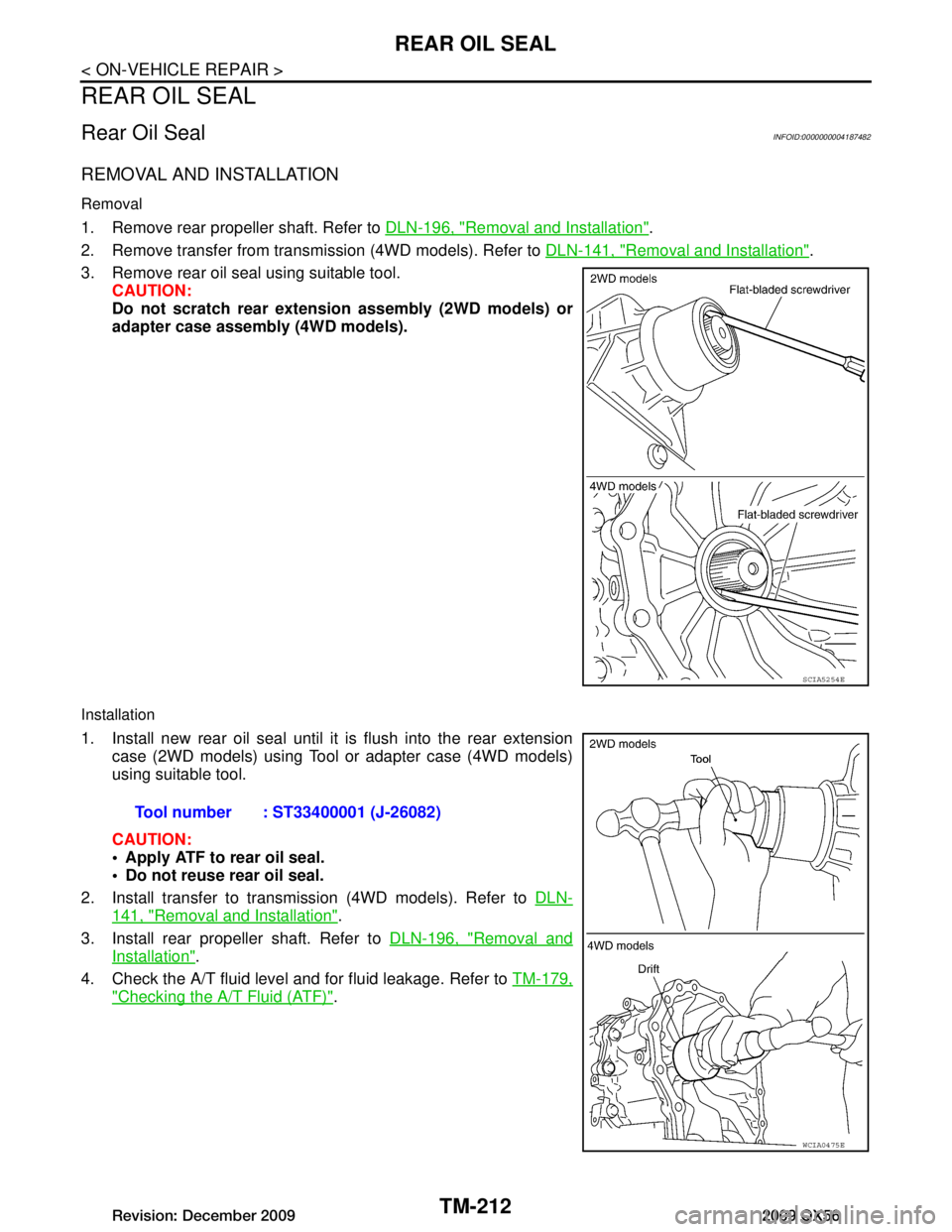
3. Remove rear oil seal using suitable tool. CAUTION:
Do not scratch rear extension assembly (2WD models) or
adapter case assembly (4WD models).
Installation
1. Install new rear oil seal until it is flush into the rear extension
case (2WD models) using Tool or adapter case (4WD models)
using suitable tool.
CAUTION:
Apply ATF to rear oil seal.
Do not reuse rear oil seal.
2. Install transfer to transmission (4WD models). Refer to DLN-
141, "Removal and Installation".
3. Install rear propeller shaft. Refer to DLN-196, "Removal and
Installation".
4. Check the A/T fluid level and for fluid leakage. Refer to TM-179,
"Checking the A/T Fluid (ATF)".
SCIA5254E
Tool number : ST33400001 (J-26082)
WCIA0475E
Revision: December 20092009 QX56
Page 3861 of 4171
FLUID COOLER SYSTEMTM-213
< ON-VEHICLE REPAIR >
CEF
G H
I
J
K L
M A
B
TM
N
O P
FLUID COOLER SYSTEM
Exploded ViewINFOID:0000000005882663
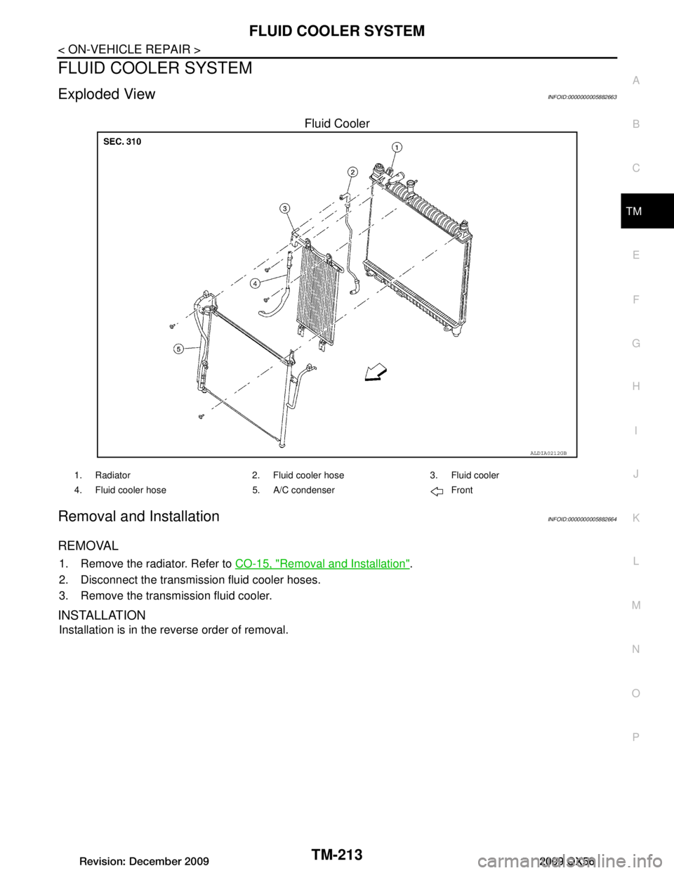
Fluid Cooler
Removal and InstallationINFOID:0000000005882664
REMOVAL
1. Remove the radiator. Refer to CO-15, "Removal and Installation".
2. Disconnect the transmission fluid cooler hoses.
3. Remove the transmission fluid cooler.
INSTALLATION
Installation is in the reverse order of removal.
ALDIA0212GB
1. Radiator 2. Fluid cooler hose 3. Fluid cooler
4. Fluid cooler hose 5. A/C condenser Front
Revision: December 20092009 QX56
Page 3862 of 4171
TM-214
< REMOVAL AND INSTALLATION >
TRANSMISSION ASSEMBLY
REMOVAL AND INSTALLATION
TRANSMISSION ASSEMBLY
Removal and Installation (2WD)INFOID:0000000005892371
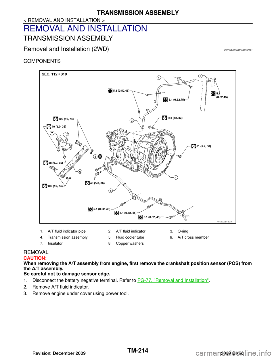
COMPONENTS
REMOVAL
CAUTION:
When removing the A/T assembly from engine, first remove the crankshaft position sensor (POS) from
the A/T assembly.
Be careful not to damage sensor edge.
1. Disconnect the battery negative terminal. Refer to PG-77, "Removal and Installation"
.
2. Remove A/T fluid indicator.
3. Remove engine under cover using power tool.
1. A/T fluid indicator pipe 2. A/T fluid indicator 3. O-ring
4. Transmission assembly 5. Fluid cooler tube 6. A/T cross member
7. Insulator 8. Copper washers
AWDIA0553GB
Revision: December 20092009 QX56
Page 3863 of 4171
TRANSMISSION ASSEMBLYTM-215
< REMOVAL AND INSTALLATION >
CEF
G H
I
J
K L
M A
B
TM
N
O P
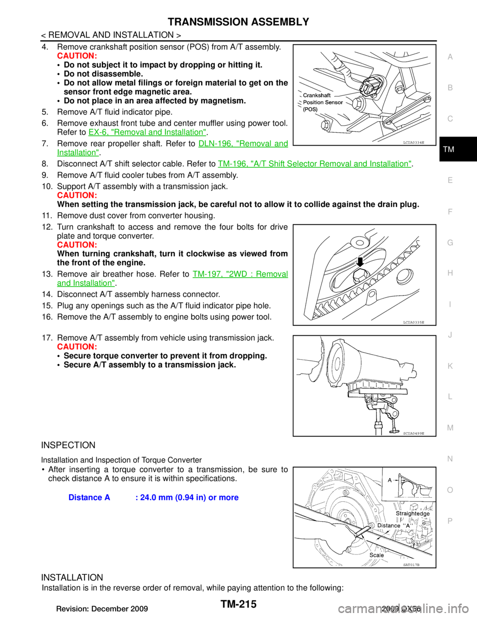
4. Remove crankshaft position sensor (POS) from A/T assembly. CAUTION:
Do not subject it to impact by dropping or hitting it.
Do not disassemble.
Do not allow metal filings or foreign material to get on the
sensor front edge magnetic area.
Do not place in an area affected by magnetism.
5. Remove A/T fluid indicator pipe.
6. Remove exhaust front tube and center muffler using power tool. Refer to EX-6, "Removal and Installation"
.
7. Remove rear propeller shaft. Refer to DLN-196, "Removal and
Installation".
8. Disconnect A/T shift selector cable. Refer to TM-196, "A/T Shift Selector Removal and Installation"
.
9. Remove A/T fluid cooler tubes from A/T assembly.
10. Support A/T assembly with a transmission jack. CAUTION:
When setting the transmission jack, be careful not to allow it to collide against the drain plug.
11. Remove dust cover from converter housing.
12. Turn crankshaft to access and remove the four bolts for drive plate and torque converter.
CAUTION:
When turning crankshaft, turn it clockwise as viewed from
the front of the engine.
13. Remove air breather hose. Refer to TM-197, "2WD : Removal
and Installation".
14. Disconnect A/T assembly harness connector.
15. Plug any openings such as the A/T fluid indicator pipe hole.
16. Remove the A/T assembly to engine bolts using power tool.
17. Remove A/T assembly from vehicle using transmission jack. CAUTION:
Secure torque converter to prevent it from dropping.
Secure A/T assembly to a transmission jack.
INSPECTION
Installation and Inspection of Torque Converter
After inserting a torque converter to a transmission, be sure to check distance A to ensure it is within specifications.
INSTALLATION
Installation is in the reverse order of removal, while paying attention to the following:
LCIA0334E
LCIA0335E
SCIA0499E
Distance A : 24.0 mm (0.94 in) or more
SAT017B
Revision: December 20092009 QX56