INFINITI QX56 2009 Factory Service Manual
QX56 2009
INFINITI
INFINITI
https://www.carmanualsonline.info/img/42/57031/w960_57031-0.png
INFINITI QX56 2009 Factory Service Manual
Page 3894 of 4171
TM-246
< DISASSEMBLY AND ASSEMBLY >
DISASSEMBLY
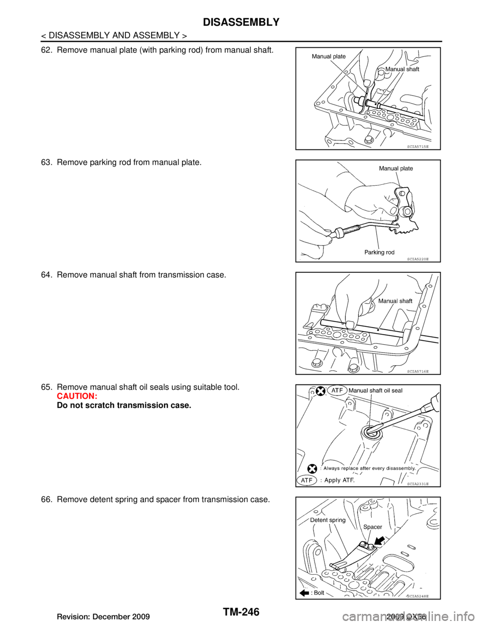
62. Remove manual plate (with parking rod) from manual shaft.
63. Remove parking rod from manual plate.
64. Remove manual shaft from transmission case.
65. Remove manual shaft oil seals using suitable tool.CAUTION:
Do not scratch transmission case.
66. Remove detent spring and spacer from transmission case.
SCIA5715E
SCIA5220E
SCIA5716E
SCIA2331E
SCIA5248E
Revision: December 20092009 QX56
Page 3895 of 4171
DISASSEMBLYTM-247
< DISASSEMBLY AND ASSEMBLY >
CEF
G H
I
J
K L
M A
B
TM
N
O P
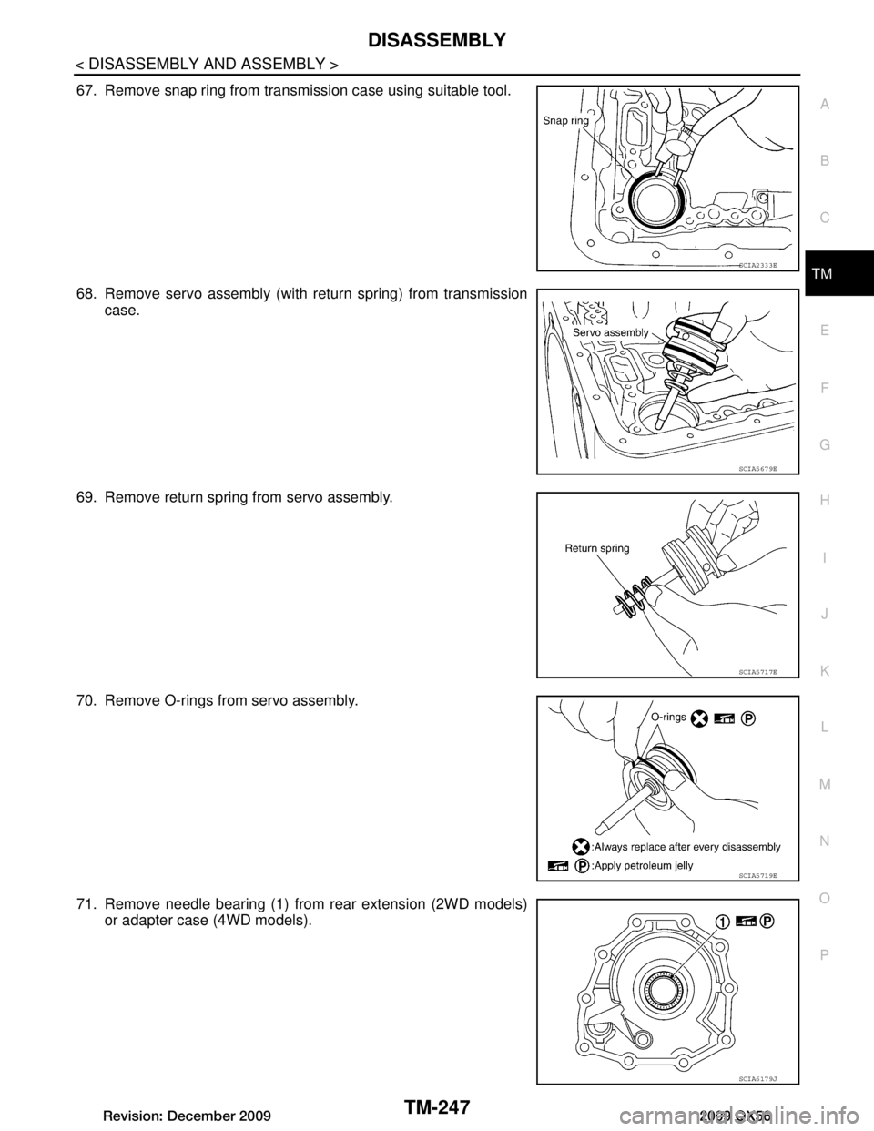
67. Remove snap ring from transmission case using suitable tool.
68. Remove servo assembly (with return spring) from transmission case.
69. Remove return spring from servo assembly.
70. Remove O-rings from servo assembly.
71. Remove needle bearing (1) from rear extension (2WD models) or adapter case (4WD models).
SCIA2333E
SCIA5679E
SCIA5717E
SCIA5719E
SCIA6179J
Revision: December 20092009 QX56
Page 3896 of 4171
TM-248
< DISASSEMBLY AND ASSEMBLY >
DISASSEMBLY
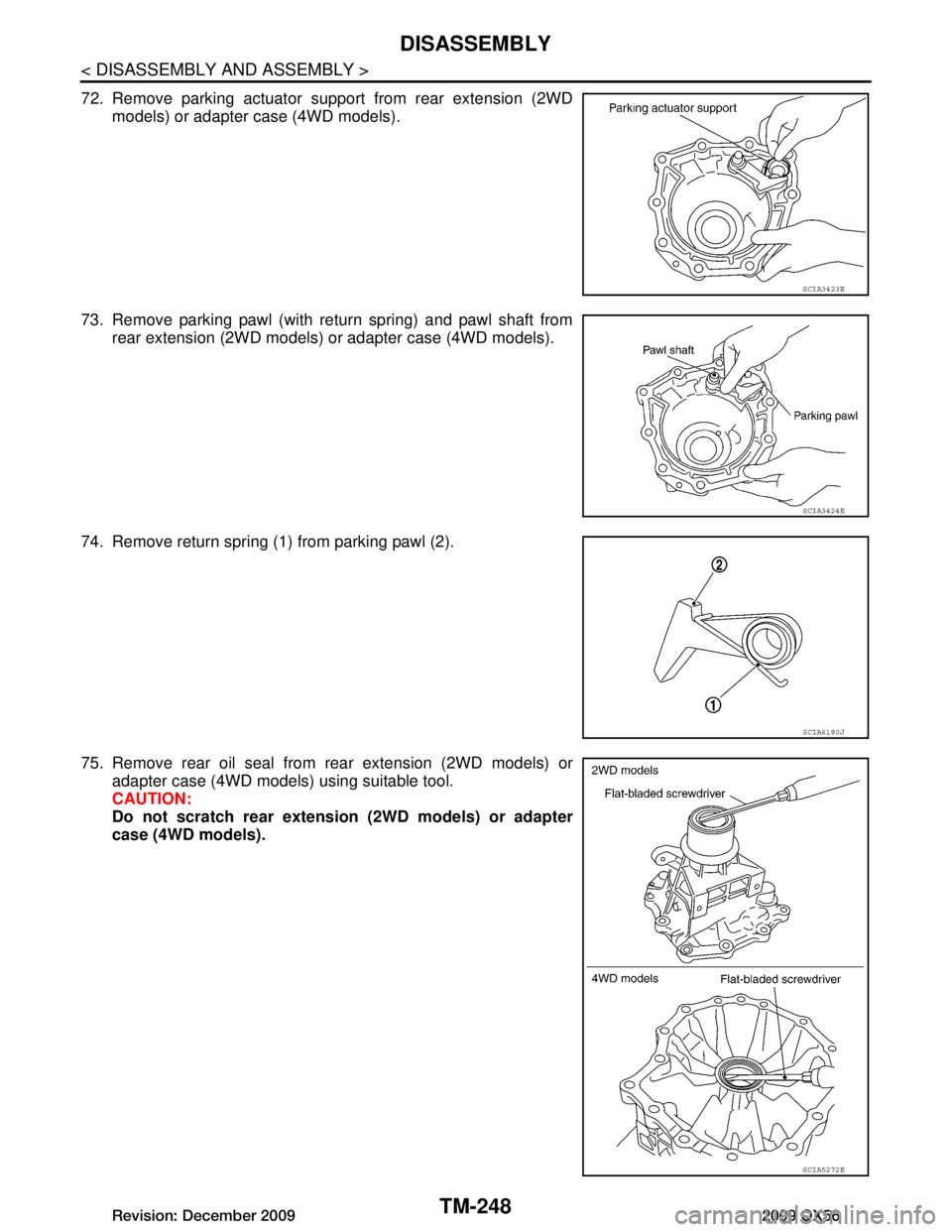
72. Remove parking actuator support from rear extension (2WD
models) or adapter case (4WD models).
73. Remove parking pawl (with return spring) and pawl shaft from rear extension (2WD models) or adapter case (4WD models).
74. Remove return spring (1) from parking pawl (2).
75. Remove rear oil seal from rear extension (2WD models) or adapter case (4WD models) using suitable tool.
CAUTION:
Do not scratch rear extension (2WD models) or adapter
case (4WD models).
SCIA3423E
SCIA3424E
SCIA6180J
SCIA5272E
Revision: December 20092009 QX56
Page 3897 of 4171
REPAIR FOR COMPONENT PARTSTM-249
< DISASSEMBLY AND ASSEMBLY >
CEF
G H
I
J
K L
M A
B
TM
N
O P
REPAIR FOR COMPONENT PARTS
Oil PumpINFOID:0000000004187490
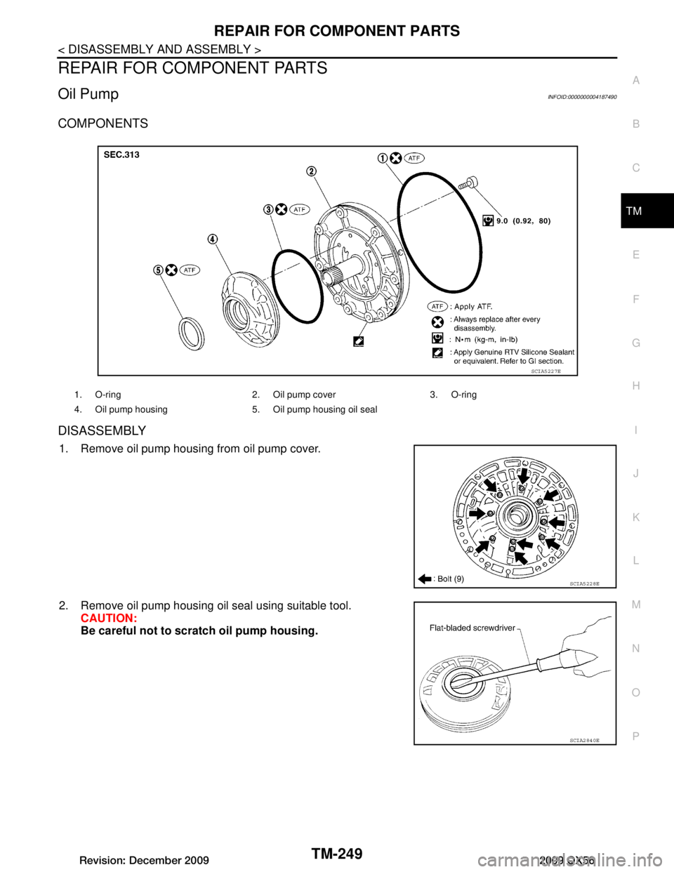
COMPONENTS
DISASSEMBLY
1. Remove oil pump housing from oil pump cover.
2. Remove oil pump housing oil seal using suitable tool. CAUTION:
Be careful not to scratch oil pump housing.
1. O-ring 2. Oil pump cover 3. O-ring
4. Oil pump housing 5. Oil pump housing oil seal
SCIA5227E
SCIA5228E
SCIA2840E
Revision: December 20092009 QX56
Page 3898 of 4171
TM-250
< DISASSEMBLY AND ASSEMBLY >
REPAIR FOR COMPONENT PARTS
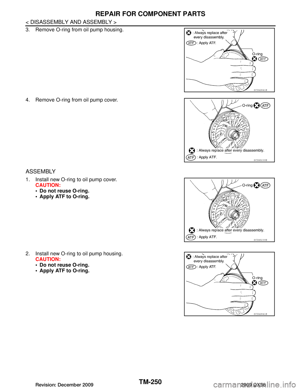
3. Remove O-ring from oil pump housing.
4. Remove O-ring from oil pump cover.
ASSEMBLY
1. Install new O-ring to oil pump cover.CAUTION:
Do not reuse O-ring.
Apply ATF to O-ring.
2. Install new O-ring to oil pump housing. CAUTION:
Do not reuse O-ring.
Apply ATF to O-ring.
SCIA2841E
SCIA5230E
SCIA5230E
SCIA2841E
Revision: December 20092009 QX56
Page 3899 of 4171
REPAIR FOR COMPONENT PARTSTM-251
< DISASSEMBLY AND ASSEMBLY >
CEF
G H
I
J
K L
M A
B
TM
N
O P
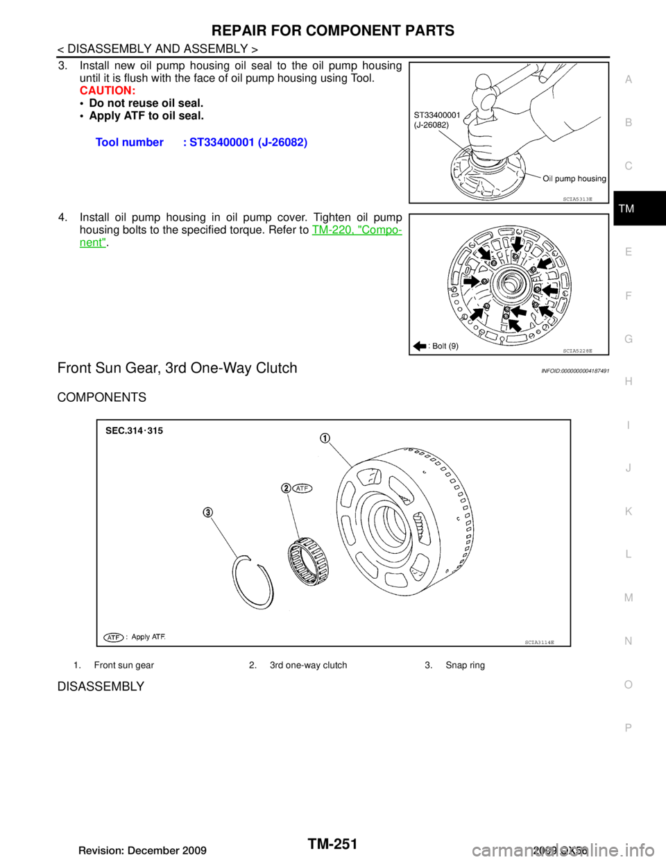
3. Install new oil pump housing oil seal to the oil pump housing until it is flush with the face of oil pump housing using Tool.
CAUTION:
Do not reuse oil seal.
Apply ATF to oil seal.
4. Install oil pump housing in oil pump cover. Tighten oil pump housing bolts to the specified torque. Refer to TM-220, "Compo-
nent".
Front Sun Gear, 3rd One-Way ClutchINFOID:0000000004187491
COMPONENTS
DISASSEMBLY
Tool number : ST33400001 (J-26082)
SCIA5313E
SCIA5228E
1. Front sun gear 2. 3rd one-way clutch 3. Snap ring
SCIA3114E
Revision: December 20092009 QX56
Page 3900 of 4171
TM-252
< DISASSEMBLY AND ASSEMBLY >
REPAIR FOR COMPONENT PARTS
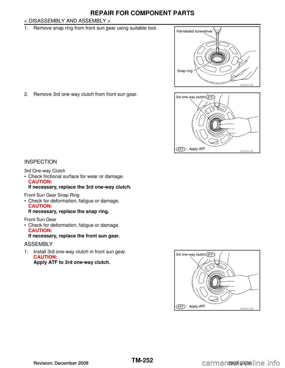
1. Remove snap ring from front sun gear using suitable tool.
2. Remove 3rd one-way clutch from front sun gear.
INSPECTION
3rd One-way Clutch
Check frictional surface for wear or damage.CAUTION:
If necessary, replace the 3rd one-way clutch.
Front Sun Gear Snap Ring
Check for deformation, fatigue or damage.CAUTION:
If necessary, replace the snap ring.
Front Sun Gear
Check for deformation, fatigue or damage.CAUTION:
If necessary, replace the front sun gear.
ASSEMBLY
1. Install 3rd one-way clutch in front sun gear. CAUTION:
Apply ATF to 3rd one-way clutch.
SCIA3110E
SCIA3111E
SCIA3111E
Revision: December 20092009 QX56
Page 3901 of 4171
REPAIR FOR COMPONENT PARTSTM-253
< DISASSEMBLY AND ASSEMBLY >
CEF
G H
I
J
K L
M A
B
TM
N
O P
2. Install snap ring in front sun gear using suitable tool.
3. Check operation of 3rd one-way clutch.
a. Hold oil pump assembly and turn front sun gear.
b. Check 3rd one-way clutch for correct locking and unlocking directions.
CAUTION:
If not as shown, check installati on direction of 3rd one-way
clutch.
Front Carrier, Input Clut ch, Rear Internal GearINFOID:0000000004187492
COMPONENTS
SCIA3110E
SCIA3131E
Revision: December 20092009 QX56
Page 3902 of 4171
TM-254
< DISASSEMBLY AND ASSEMBLY >
REPAIR FOR COMPONENT PARTS
DISASSEMBLY
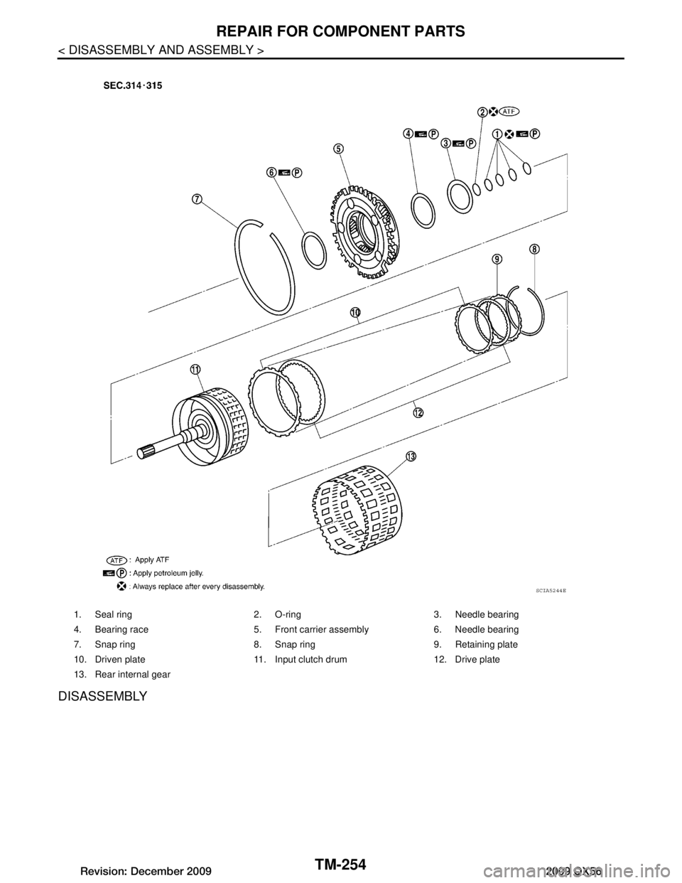
1. Seal ring 2. O-ring 3. Needle bearing
4. Bearing race 5. Front carrier assembly 6. Needle bearing
7. Snap ring 8. Snap ring 9. Retaining plate
10. Driven plate 11. Input clutch drum 12. Drive plate
13. Rear internal gear
SCIA5244E
Revision: December 20092009 QX56
Page 3903 of 4171
REPAIR FOR COMPONENT PARTSTM-255
< DISASSEMBLY AND ASSEMBLY >
CEF
G H
I
J
K L
M A
B
TM
N
O P
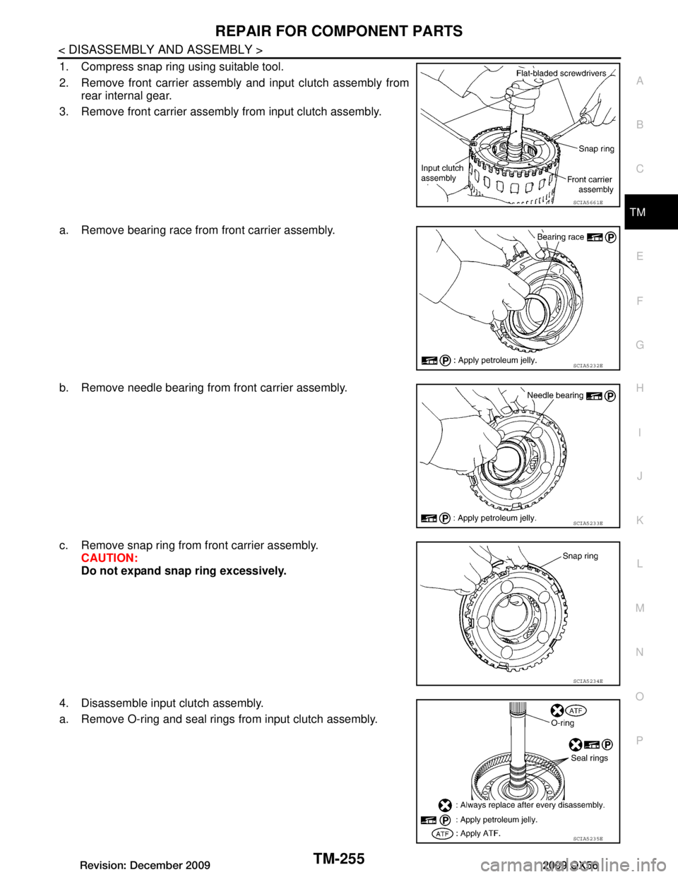
1. Compress snap ring using suitable tool.
2. Remove front carrier assembly and input clutch assembly from rear internal gear.
3. Remove front carrier assembly from input clutch assembly.
a. Remove bearing race from front carrier assembly.
b. Remove needle bearing from front carrier assembly.
c. Remove snap ring from front carrier assembly. CAUTION:
Do not expand snap ring excessively.
4. Disassemble input clutch assembly.
a. Remove O-ring and seal rings from input clutch assembly.
SCIA5661E
SCIA5232E
SCIA5233E
SCIA5234E
SCIA5235E
Revision: December 20092009 QX56
