height INFINITI QX56 2009 Factory Workshop Manual
[x] Cancel search | Manufacturer: INFINITI, Model Year: 2009, Model line: QX56, Model: INFINITI QX56 2009Pages: 4171, PDF Size: 84.65 MB
Page 1889 of 4171
EM-66
< ON-VEHICLE REPAIR >
OIL SEAL
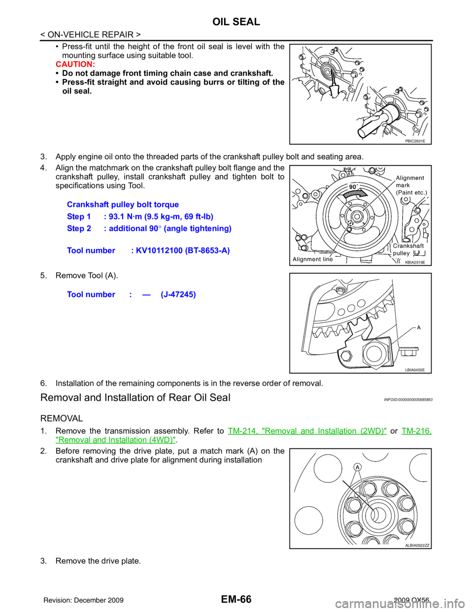
• Press-fit until the height of the front oil seal is level with themounting surface using suitable tool.
CAUTION:
• Do not damage front timing chain case and crankshaft.
• Press-fit straight and avoid cau sing burrs or tilting of the
oil seal.
3. Apply engine oil onto the threaded parts of the crankshaft pulley bolt and seating area.
4. Align the matchmark on the crankshaft pulley bolt flange and the crankshaft pulley, install crankshaft pulley and tighten bolt to
specifications using Tool.
5. Remove Tool (A).
6. Installation of the remaining components is in the reverse order of removal.
Removal and Installation of Rear Oil SealINFOID:0000000005885893
REMOVAL
1. Remove the transmission assembly. Refer to TM-214, "Removal and Installation (2WD)" or TM-216,
"Removal and Installation (4WD)".
2. Before removing the drive plate, put a match mark (A) on the crankshaft and drive plate for alignment during installation
3. Remove the drive plate.
PBIC2931E
Crankshaft pulley bolt torque
Step 1 : 93.1 N·m (9.5 kg-m, 69 ft-lb)
Step 2 : additional 90 ° (angle tightening)
Tool number : KV10112100 (BT-8653-A)
KBIA2519E
Tool number : — (J-47245)
LBIA0455E
ALBIA0522ZZ
Revision: December 20092009 QX56
Page 1894 of 4171
CYLINDER HEADEM-71
< ON-VEHICLE REPAIR >
C
DE
F
G H
I
J
K L
M A
EM
NP
O
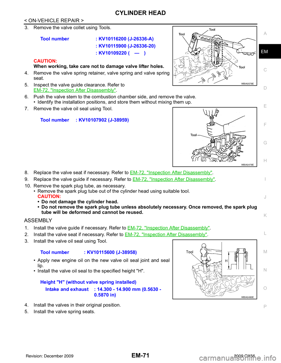
3. Remove the valve collet using Tools.
CAUTION:
When working, take care not to damage valve lifter holes.
4. Remove the valve spring retainer, valve spring and valve spring seat.
5. Inspect the valve guide clearance. Refer to EM-72, "
Inspection After Disassembly".
6. Push the valve stem to the combustion chamber side, and remove the valve. • Identify the installation positions, and store them without mixing them up.
7. Remove the valve oil seal using Tool.
8. Replace the valve seat if necessary. Refer to EM-72, "
Inspection After Disassembly".
9. Replace the valve guide if necessary. Refer to EM-72, "
Inspection After Disassembly".
10. Remove the spark plug tube, as necessary. • Remove the spark plug tube out of the cylinder head using suitable tool.
CAUTION:
• Do not damage the cylinder head.
• Do not remove the spark plug tube unless absolutely necessary. Once removed, the spark plug tube will be deformed and cannot be reused.
ASSEMBLY
1. Install the valve guide if necessary. Refer to EM-72, "Inspection After Disassembly".
2. Install the valve seat if necessary. Refer to EM-72, "
Inspection After Disassembly".
3. Install the valve oil seal using Tool.
• Apply new engine oil on the new valve oil seal joint and seallip.
• Install the valve oil seal to the specified height "H".
4. Install the valves in their original position.
5. Install the valve spring seats. Tool number
: KV10116200 (J-26336-A)
: KV10115900 (J-26336-20)
: KV10109220 ( — )
Tool number : KV10107902 (J-38959)
WBIA0578E
WBIA0478E
Tool number : KV10115600 (J-38958)
Height "H" (without valve spring installed) Intake and exhaust : 14.300 - 14.900 mm (0.5630 - 0.5870 in)
WBIA0490E
Revision: December 20092009 QX56
Page 1895 of 4171
EM-72
< ON-VEHICLE REPAIR >
CYLINDER HEAD
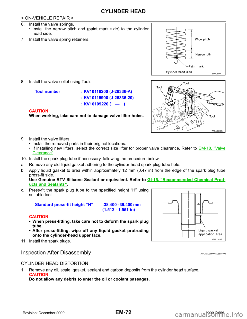
6. Install the valve springs.• Install the narrow pitch end (paint mark side) to the cylinderhead side.
7. Install the valve spring retainers.
8. Install the valve collet using Tools.
CAUTION:
When working, take care not to damage valve lifter holes.
9. Install the valve lifters. • Install the removed parts in their original locations.
• If installing new lifters, select the correct size lifter for proper valve clearance. Refer to EM-18, "
Va l v e
Clearance".
10. Install the spark plug tube if necessary, following the procedure below.
a. Remove any old liquid gasket adhering to the cylinder-head spark plug tube hole.
b. Apply liquid gasket to area within approximately 12 mm (0.47 in) from the edge of the spark plug tube
press-fit side.
Use Genuine RTV Silicone Seal ant or equivalent. Refer to GI-15, "
Recommended Chemical Prod-
ucts and Sealants".
c. Press-fit the spark plug tube to the specified height “H” using suitable tool.
CAUTION:
• When press-fitting, take care not to deform the spark plugtube.
• After press-fitting, wipe off any liquid gasket protruding
onto the cylinder-head upper face.
11. Install the spark plugs.
Inspection After DisassemblyINFOID:0000000005885898
CYLINDER HEAD DISTORTION
1. Remove any oil, scale, gasket, sealant and carbon deposits from the cylinder head surface. CAUTION:
Do not allow any debris to en ter the oil or coolant passages.
SEM085D
Tool number : KV10116200 (J-26336-A)
: KV10115900 (J-26336-20)
: KV10109220 ( — )
WBIA0578E
Standard press-fit height “H” :38.400 - 39.400 mm (1.512 - 1.551 in)
KBIA1248E
Revision: December 20092009 QX56
Page 1900 of 4171
CYLINDER HEADEM-77
< ON-VEHICLE REPAIR >
C
DE
F
G H
I
J
K L
M A
EM
NP
O
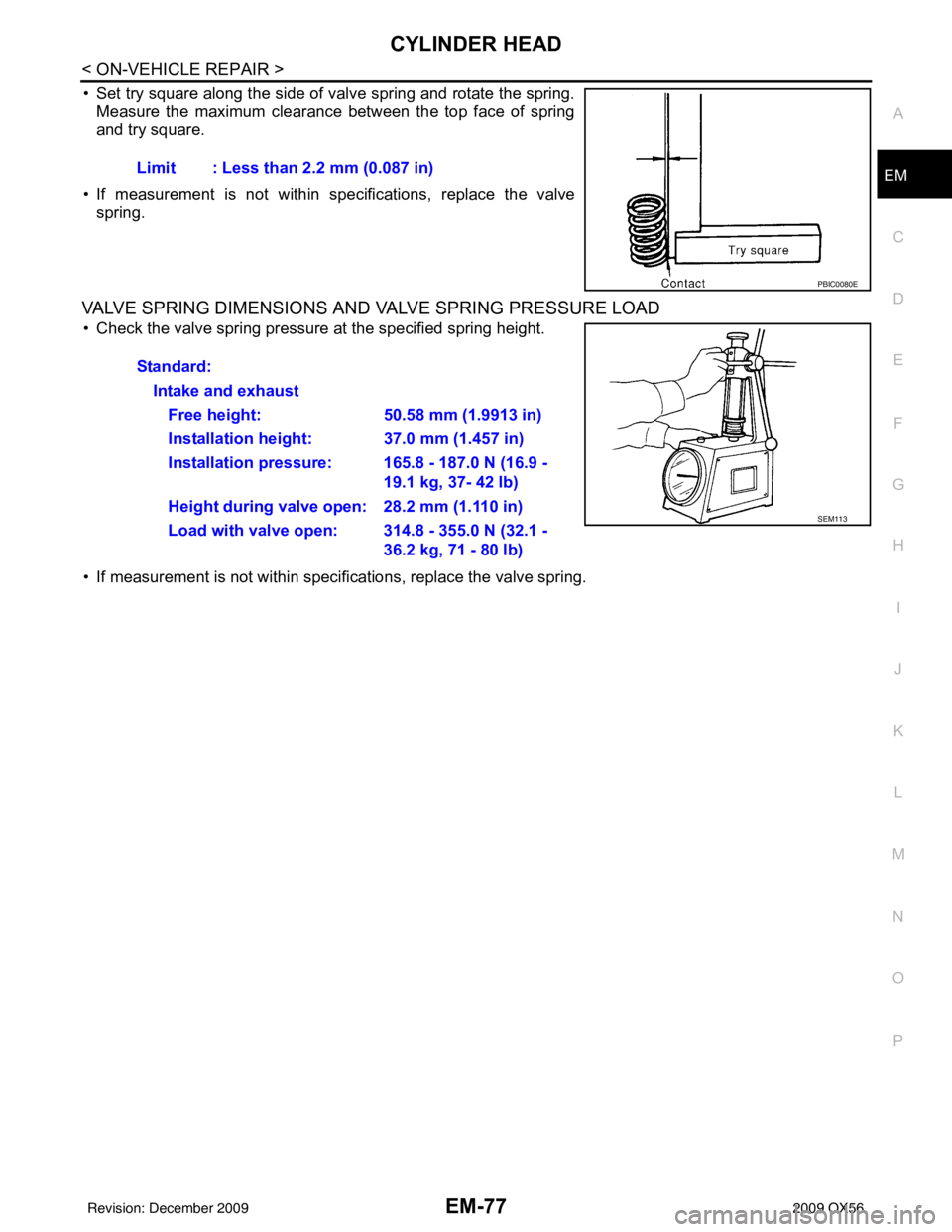
• Set try square along the side of valve spring and rotate the spring.
Measure the maximum clearance between the top face of spring
and try square.
• If measurement is not within specifications, replace the valve spring.
VALVE SPRING DIMENSIONS AND VALVE SPRING PRESSURE LOAD
• Check the valve spring pressure at the specified spring height.
• If measurement is not within specifications, replace the valve spring. Limit : Less than 2.2 mm (0.087 in)
PBIC0080E
Standard:
Intake and exhaustFree height: 50.58 mm (1.9913 in)
Installation height: 37.0 mm (1.457 in)
Installation pressure: 165.8 - 187.0 N (16.9 - 19.1 kg, 37- 42 lb)
Height during valve open: 28.2 mm (1.110 in)
Load with valve open: 314.8 - 355.0 N (32.1 - 36.2 kg, 71 - 80 lb)
SEM113
Revision: December 20092009 QX56
Page 1921 of 4171
EM-98
< DISASSEMBLY AND ASSEMBLY >
ENGINE UNIT
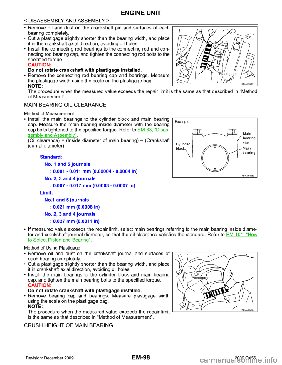
• Remove oil and dust on the crankshaft pin and surfaces of eachbearing completely.
• Cut a plastigage slightly shorter than the bearing width, and place
it in the crankshaft axial direction, avoiding oil holes.
• Install the connecting rod beari ngs to the connecting rod and con-
necting rod bearing cap, and tighten the connecting rod bolts to the
specified torque.
CAUTION:
Do not rotate crankshaft with plastigage installed.
• Remove the connecting rod bear ing cap and bearings. Measure
the plastigage width using the scale on the plastigage bag.
NOTE:
The procedure when the measured value exceeds the repair limit is the same as that described in “Method
of Measurement”.
MAIN BEARING OIL CLEARANCE
Method of Measurement
• Install the main bearings to the cylinder block and main bearing cap. Measure the main bearing inside diameter with the bearing
cap bolts tightened to the specified torque. Refer to EM-83, "
Disas-
sembly and Assembly".
(Oil clearance) = (Inside diameter of main bearing) – (Crankshaft
journal diameter)
• If measured value exceeds the repair limit, select main bearings referring to the main bearing inside diame-
ter and crankshaft journal diameter, so that the oil clearance satisfies the standard. Refer to EM-101, "
How
to Select Piston and Bearing".
Method of Using Plastigage
• Remove oil and dust on the crankshaft journal and surfaces of
each bearing completely.
• Cut a plastigage slightly shorter than the bearing width, and place it in crankshaft axial direction, avoiding oil holes.
• Install the main bearings to the cylinder block and main bearing cap, and tighten the main bearing bolts to the specified torque.
CAUTION:
Do not rotate crankshaft with plastigage installed.
• Remove bearing cap and bearings. Measure plastigage width using the scale on the plastigage bag.
NOTE:
The procedure when the measured value exceeds the repair limit
is the same as that descri bed in “Method of Measurement”.
CRUSH HEIGHT OF MAIN BEARING
KBIA2550E
Standard:
No. 1 and 5 journals : 0.001 - 0.011 mm (0.00004 - 0.0004 in)
No. 2, 3 and 4 journals : 0.007 - 0.017 mm (0.0003 - 0.0007 in)
Limit: No.1 and 5 journals : 0.021 mm (0.0008 in)
No. 2, 3 and 4 journals : 0.027 mm (0.0011 in)
PBIC1644E
KBIA2551E
Revision: December 20092009 QX56
Page 1922 of 4171
ENGINE UNITEM-99
< DISASSEMBLY AND ASSEMBLY >
C
DE
F
G H
I
J
K L
M A
EM
NP
O
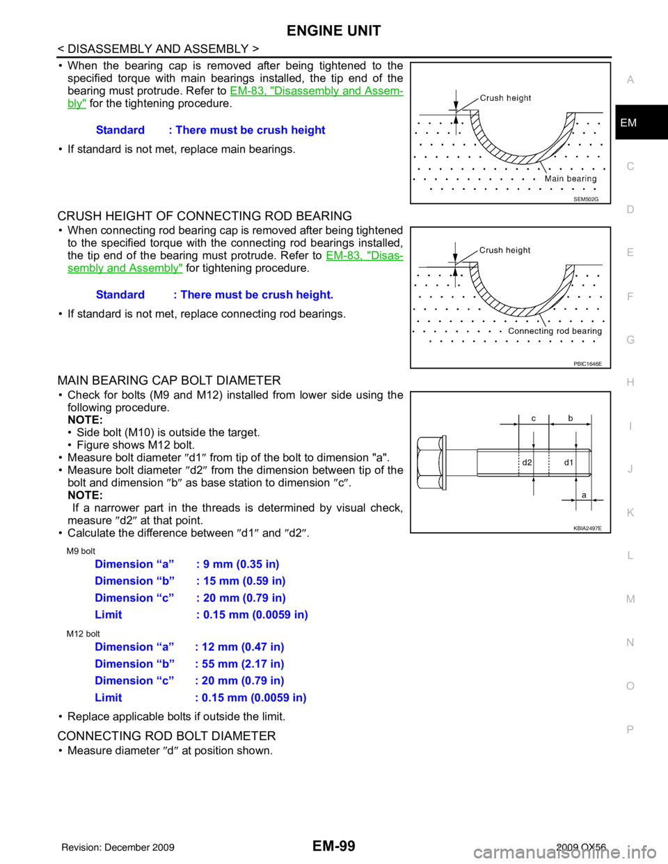
• When the bearing cap is removed after being tightened to the
specified torque with main bearings installed, the tip end of the
bearing must protrude. Refer to EM-83, "
Disassembly and Assem-
bly" for the tightening procedure.
• If standard is not met, replace main bearings.
CRUSH HEIGHT OF CONNECTING ROD BEARING
• When connecting rod bearing cap is removed after being tightened to the specified torque with the connecting rod bearings installed,
the tip end of the bearing must protrude. Refer to EM-83, "
Disas-
sembly and Assembly" for tightening procedure.
• If standard is not met, replace connecting rod bearings.
MAIN BEARING CAP BOLT DIAMETER
• Check for bolts (M9 and M12) installed from lower side using the following procedure.
NOTE:
• Side bolt (M10) is outside the target.
• Figure shows M12 bolt.
• Measure bolt diameter ″ d1″ from tip of the bolt to dimension "a".
• Measure bolt diameter ″d2″ from the dimension between tip of the
bolt and dimension ″b ″ as base station to dimension ″c″ .
NOTE:
If a narrower part in the threads is determined by visual check,
measure ″d2″ at that point.
• Calculate the difference between ″d1″ and ″d2″ .
M9 bolt
M12 bolt
• Replace applicable bolts if outside the limit.
CONNECTING ROD BOLT DIAMETER
• Measure diameter ″d ″ at position shown.
Standard : There must be crush height
SEM502G
Standard : There must be crush height.
PBIC1646E
KBIA2497E
Dimension “a” : 9 mm (0.35 in)
Dimension “b” : 15 mm (0.59 in)
Dimension “c” : 20 mm (0.79 in)
Limit : 0.15 mm (0.0059 in)
Dimension “a” : 12 mm (0.47 in)
Dimension “b” : 55 mm (2.17 in)
Dimension “c” : 20 mm (0.79 in)
Limit : 0.15 mm (0.0059 in)
Revision: December 20092009 QX56
Page 1932 of 4171
SERVICE DATA AND SPECIFICATIONS (SDS)EM-109
< SERVICE DATA AND SPECIFICATIONS (SDS)
C
DE
F
G H
I
J
K L
M A
EM
NP
O
Unit: mm (in)
SPARK PLUG
Unit: mm (in)
*: Always check with the Parts Department for the latest parts information
CAMSHAFT AND CAMSHAFT BEARING
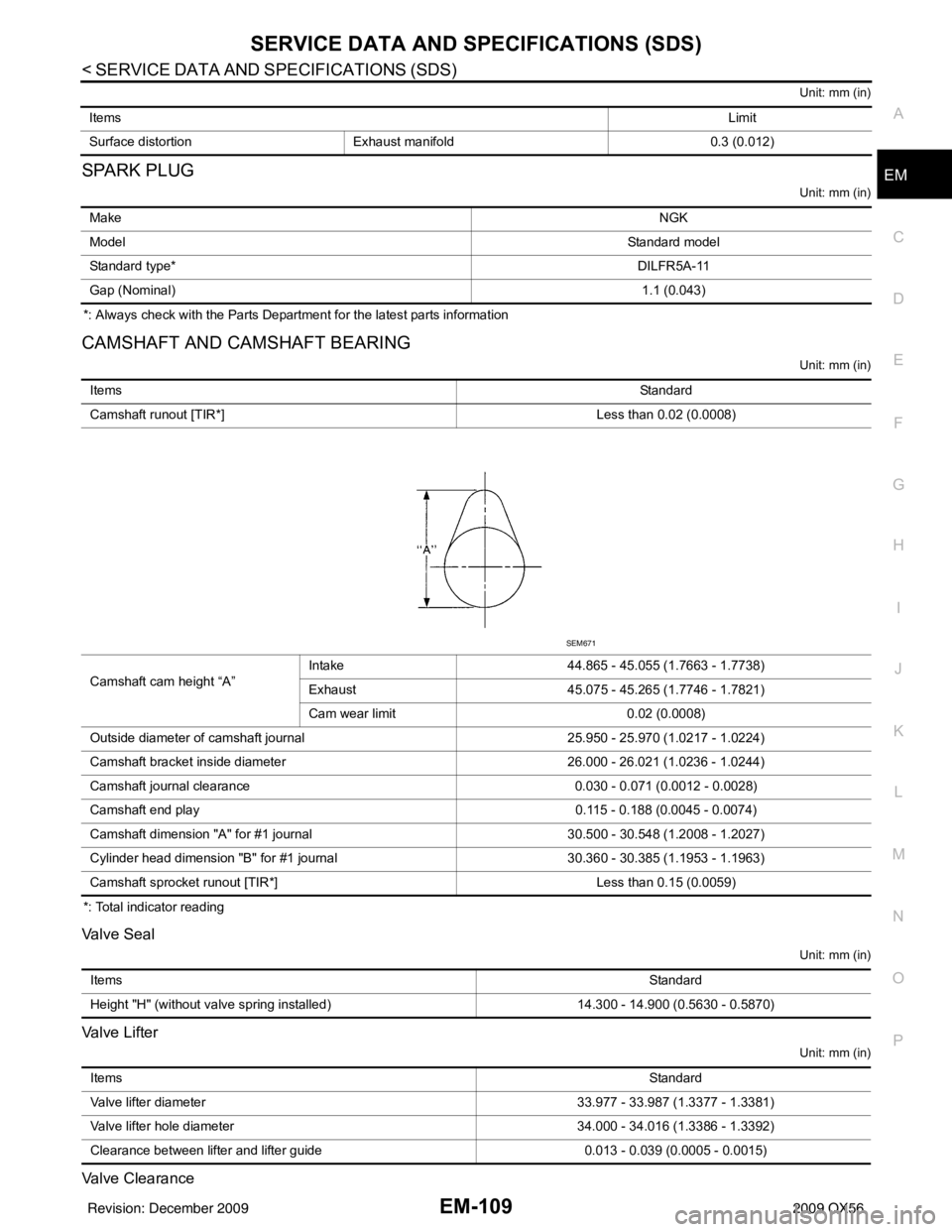
Unit: mm (in)
*: Total indicator reading
Valve Seal
Unit: mm (in)
Valve Lifter
Unit: mm (in)
Valve Clearance
Items
Limit
Surface distortion Exhaust manifold 0.3 (0.012)
Make NGK
Model Standard model
Standard type* DILFR5A-11
Gap (Nominal) 1.1 (0.043)
ItemsStandard
Camshaft runout [TIR*] Less than 0.02 (0.0008)
Camshaft cam height “A” Intake
44.865 - 45.055 (1.7663 - 1.7738)
Exhaust 45.075 - 45.265 (1.7746 - 1.7821)
Cam wear limit 0.02 (0.0008)
Outside diameter of camshaft journal 25.950 - 25.970 (1.0217 - 1.0224)
Camshaft bracket inside diameter 26.000 - 26.021 (1.0236 - 1.0244)
Camshaft journal clearance 0.030 - 0.071 (0.0012 - 0.0028)
Camshaft end play 0.115 - 0.188 (0.0045 - 0.0074)
Camshaft dimension "A" for #1 journal 30.500 - 30.548 (1.2008 - 1.2027)
Cylinder head dimension "B" for #1 journal 30.360 - 30.385 (1.1953 - 1.1963)
Camshaft sprocket runout [TIR*] Less than 0.15 (0.0059)
SEM671
Items Standard
Height "H" (without valve spring installed) 14.300 - 14.900 (0.5630 - 0.5870)
Items Standard
Valve lifter diameter 33.977 - 33.987 (1.3377 - 1.3381)
Valve lifter hole diameter 34.000 - 34.016 (1.3386 - 1.3392)
Clearance between lifter and lifter guide 0.013 - 0.039 (0.0005 - 0.0015)
Revision: December 20092009 QX56
Page 1934 of 4171
SERVICE DATA AND SPECIFICATIONS (SDS)EM-111
< SERVICE DATA AND SPECIFICATIONS (SDS)
C
DE
F
G H
I
J
K L
M A
EM
NP
O
Unit: mm (in)
Spark Plug Tube
Unit: mm (in)
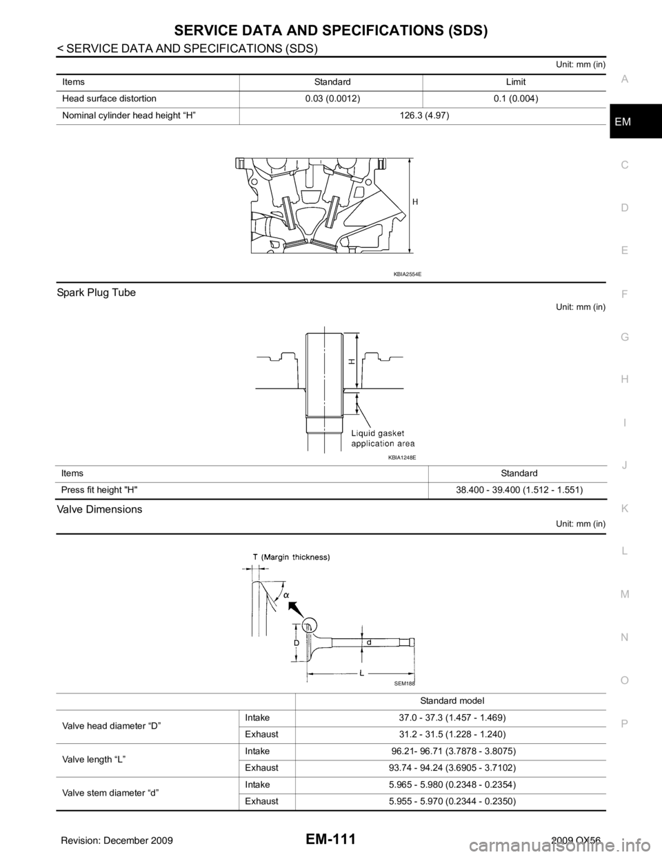
Valve Dimensions
Unit: mm (in)
Items
StandardLimit
Head surface distortion 0.03 (0.0012)0.1 (0.004)
Nominal cylinder head height “H” 126.3 (4.97)
KBIA2554E
Items Standard
Press fit height "H" 38.400 - 39.400 (1.512 - 1.551)
KBIA1248E
Standard model
Valve head diameter “D” Intake
37.0 - 37.3 (1.457 - 1.469)
Exhaust 31.2 - 31.5 (1.228 - 1.240)
Valve length “L” Intake
96.21- 96.71 (3.7878 - 3.8075)
Exhaust 93.74 - 94.24 (3.6905 - 3.7102)
Valve stem diameter “d” Intake
5.965 - 5.980 (0.2348 - 0.2354)
Exhaust 5.955 - 5.970 (0.2344 - 0.2350)
SEM188
Revision: December 20092009 QX56
Page 1936 of 4171
SERVICE DATA AND SPECIFICATIONS (SDS)EM-113
< SERVICE DATA AND SPECIFICATIONS (SDS)
C
DE
F
G H
I
J
K L
M A
EM
NP
O
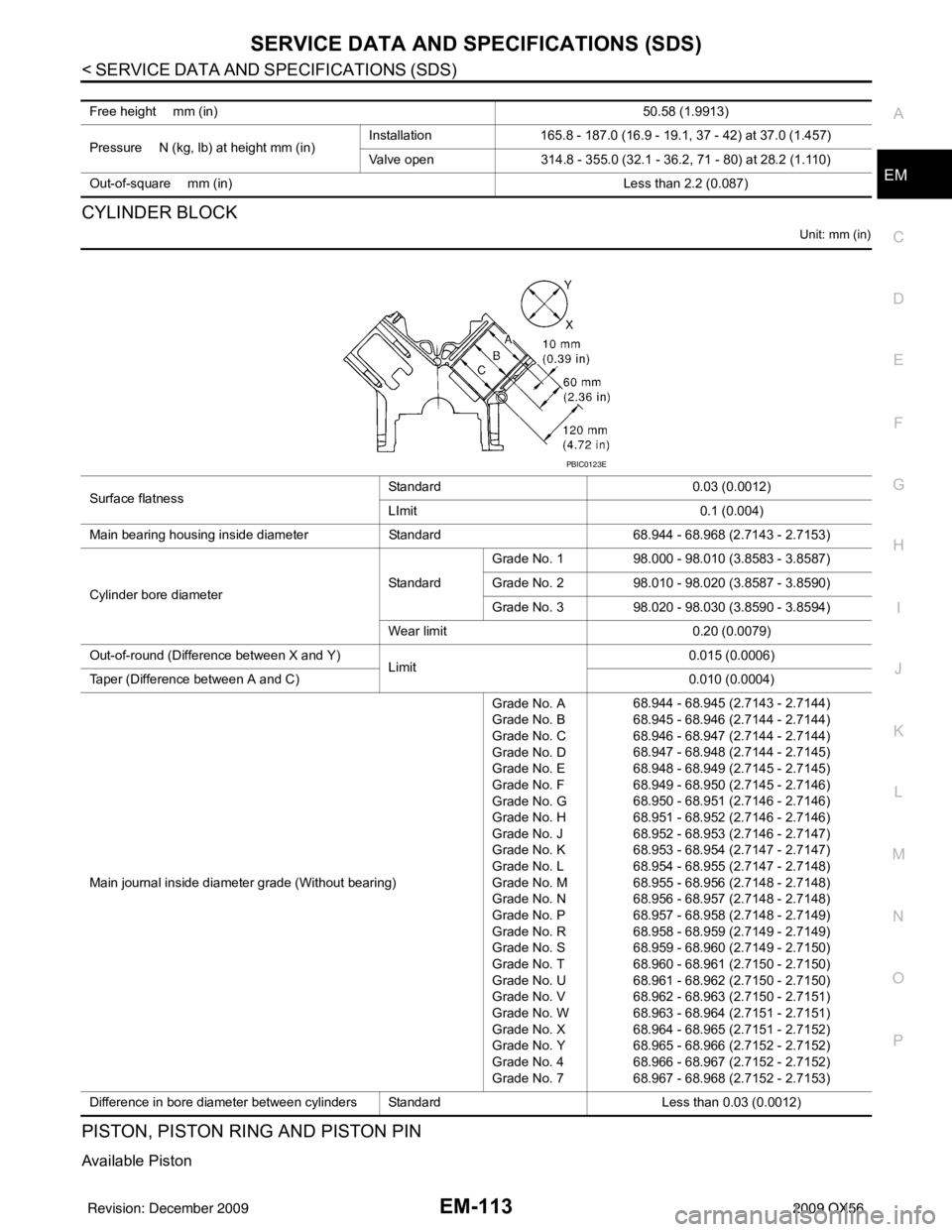
CYLINDER BLOCK
Unit: mm (in)
PISTON, PISTON RING AND PISTON PIN
Available Piston
Free height mm (in)
50.58 (1.9913)
Pressure N (kg, lb) at height mm (in) Installation
165.8 - 187.0 (16.9 - 19.1, 37 - 42) at 37.0 (1.457)
Valve open 314.8 - 355.0 (32.1 - 36.2, 71 - 80) at 28.2 (1.110)
Out-of-square mm (in) Less than 2.2 (0.087)
Surface flatnessStandard
0.03 (0.0012)
LImit 0.1 (0.004)
Main bearing housing inside diameter Standard68.944 - 68.968 (2.7143 - 2.7153)
Cylinder bore diameter StandardGrade No. 1
98.000 - 98.010 (3.8583 - 3.8587)
Grade No. 2 98.010 - 98.020 (3.8587 - 3.8590)
Grade No. 3 98.020 - 98.030 (3.8590 - 3.8594)
Wear limit 0.20 (0.0079)
Out-of-round (Difference between X and Y) Limit 0.015 (0.0006)
Taper (Difference between A and C) 0.010 (0.0004)
Main journal inside diameter grade (Without bearing) Grade No. A
Grade No. B
Grade No. C
Grade No. D
Grade No. E
Grade No. F
Grade No. G
Grade No. H
Grade No. J
Grade No. K
Grade No. L
Grade No. M
Grade No. N
Grade No. P
Grade No. R
Grade No. S
Grade No. T
Grade No. U
Grade No. V
Grade No. W
Grade No. X
Grade No. Y
Grade No. 4
Grade No. 768.944 - 68.945 (2.7143 - 2.7144)
68.945 - 68.946 (2.7144 - 2.7144)
68.946 - 68.947 (2.7144 - 2.7144)
68.947 - 68.948 (2.7144 - 2.7145)
68.948 - 68.949 (2.7145 - 2.7145)
68.949 - 68.950 (2.7145 - 2.7146)
68.950 - 68.951 (2.7146 - 2.7146)
68.951 - 68.952 (2.7146 - 2.7146)
68.952 - 68.953 (2.7146 - 2.7147)
68.953 - 68.954 (2.7147 - 2.7147)
68.954 - 68.955 (2.7147 - 2.7148)
68.955 - 68.956 (2.7148 - 2.7148)
68.956 - 68.957 (2.7148 - 2.7148)
68.957 - 68.958 (2.7148 - 2.7149)
68.958 - 68.959 (2.7149 - 2.7149)
68.959 - 68.960 (2.7149 - 2.7150)
68.960 - 68.961 (2.7150 - 2.7150)
68.961 - 68.962 (2.7150 - 2.7150)
68.962 - 68.963 (2.7150 - 2.7151)
68.963 - 68.964 (2.7151 - 2.7151)
68.964 - 68.965 (2.7151 - 2.7152)
68.965 - 68.966 (2.7152 - 2.7152)
68.966 - 68.967 (2.7152 - 2.7152)
68.967 - 68.968 (2.7152 - 2.7153)
Difference in bore diameter between cylinders Standard Less than 0.03 (0.0012)
PBIC0123E
Revision: December 20092009 QX56
Page 1948 of 4171
EXHAUST SYSTEMEX-7
< ON-VEHICLE REPAIR >
C
DE
F
G H
I
J
K L
M A
EX
NP
O
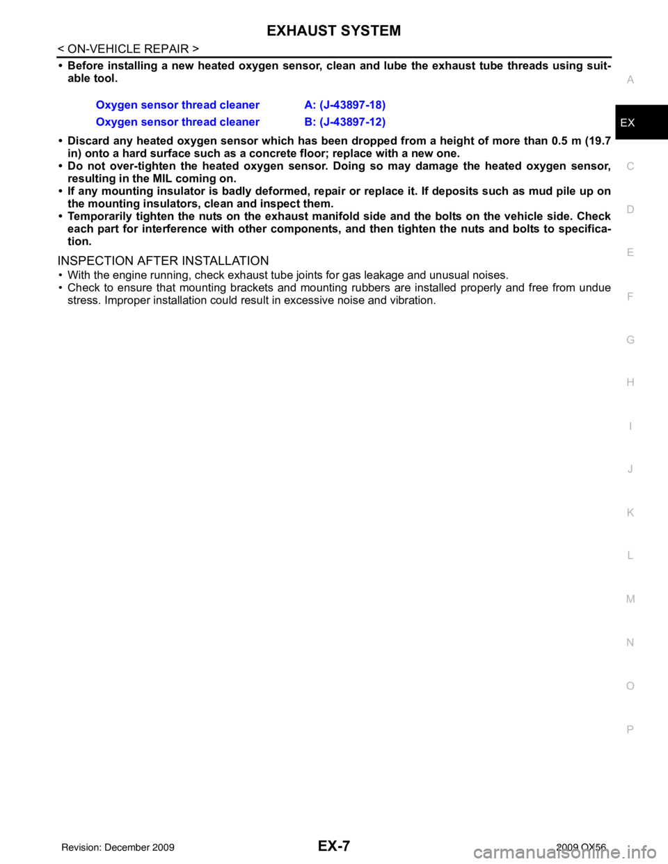
• Before installing a new heated o
xygen sensor, clean and lube the exhaust tube threads using suit-
able tool.
• Discard any heated oxygen sensor which has been dr opped from a height of more than 0.5 m (19.7
in) onto a hard surface such as a co ncrete floor; replace with a new one.
• Do not over-tighten the heated oxygen sensor. Doing so may damage the heated oxygen sensor, resulting in the MIL coming on.
• If any mounting insulator is badly deformed, repair or replace it. If deposits such as mud pile up on
the mounting insulators, clean and inspect them.
• Temporarily tighten the nuts on the exhaust manifold side and th e bolts on the vehicle side. Check
each part for interference with other components, an d then tighten the nuts and bolts to specifica-
tion.
INSPECTION AFTER INSTALLATION
• With the engine running, check exhaust tube joints for gas leakage and unusual noises.
• Check to ensure that mounting brackets and mount ing rubbers are installed properly and free from undue
stress. Improper installation could resu lt in excessive noise and vibration.
Oxygen sensor thread cleaner A: (J-43897-18)
Oxygen sensor thread cleaner B: (J-43897-12)
Revision: December 20092009 QX56