bulb INFINITI QX56 2009 Factory Service Manual
[x] Cancel search | Manufacturer: INFINITI, Model Year: 2009, Model line: QX56, Model: INFINITI QX56 2009Pages: 4171, PDF Size: 84.65 MB
Page 1382 of 4171
![INFINITI QX56 2009 Factory Service Manual
ON BOARD DIAGNOSTIC (OBD) SYSTEMEC-55
< FUNCTION DIAGNOSIS > [VK56DE]
C
D
E
F
G H
I
J
K L
M A
EC
NP
O
1. If the ignition switch stays ON after repair work, be su
re to turn ignition switch OFF once. INFINITI QX56 2009 Factory Service Manual
ON BOARD DIAGNOSTIC (OBD) SYSTEMEC-55
< FUNCTION DIAGNOSIS > [VK56DE]
C
D
E
F
G H
I
J
K L
M A
EC
NP
O
1. If the ignition switch stays ON after repair work, be su
re to turn ignition switch OFF once.](/img/42/57031/w960_57031-1381.png)
ON BOARD DIAGNOSTIC (OBD) SYSTEMEC-55
< FUNCTION DIAGNOSIS > [VK56DE]
C
D
E
F
G H
I
J
K L
M A
EC
NP
O
1. If the ignition switch stays ON after repair work, be su
re to turn ignition switch OFF once. Wait at least 10
seconds and then turn it ON (engine stopped) again.
2. Perform TM-30, "OBD-II Diagnostic Trouble Code (DTC)"
. (The DTC in TCM will be erased)
3. Select Service $04 with GST (Generic Scan Tool).
No Tools
NOTE:
If the DTC is not for AT related items (see EC-456, "DTC Index"
), skip step 2.
1. If the ignition switch stays ON after repair work, be sure to turn ignition switch OFF once.
Wait at least 10 seconds and then turn it ON (engine stopped) again.
2. Perform TM-30, "OBD-II Diagnostic Trouble Code (DTC)"
. (The DTC in the TCM will be erased.)
3. Change the diagnostic test mode from Mode II to Mode I by depressing the accelerator pedal. Refer to
EC-55, "Malfunction Indicator Lamp (MIL)"
.
If the battery is disconnected, the emission-relate d diagnostic information will be lost within 24
hours.
The following data are cleared when the ECM memory is erased.
- Diagnostic trouble codes
- 1st trip diagnostic trouble codes
- Freeze frame data
- 1st trip freeze frame data
- System readiness test (SRT) codes
- Test values
Actual work procedures are explained using a DTC as an ex ample. Be careful so that not only the DTC, but all
of the data listed above, are cleared from the ECM memory during work procedures.
Malfunction Indicator Lamp (MIL)INFOID:0000000003771316
DESCRIPTION
The MIL is located on the instrument panel.
1. The MIL will light up when the ignition switch is turned ON with-
out the engine running. This is a bulb check.
If the MIL does not light up, refer to MWI-18
or see EC-41.
2. When the engine is start ed, the MIL should go off.
If the MIL remains on, the on board diagnostic system has
detected an engine system malfunction.
ON BOARD DIAGNOSTIC SYSTEM FUNCTION
The on board diagnostic system has the following three functions.
SEF217U
Revision: December 20092009 QX56
Page 1383 of 4171
![INFINITI QX56 2009 Factory Service Manual
EC-56
< FUNCTION DIAGNOSIS >[VK56DE]
ON BOARD DIAGNOSTIC (OBD) SYSTEM
When there is an open circuit on MIL circuit, the ECM c
annot warn the driver by lighting up MIL when there is
malfunction on eng INFINITI QX56 2009 Factory Service Manual
EC-56
< FUNCTION DIAGNOSIS >[VK56DE]
ON BOARD DIAGNOSTIC (OBD) SYSTEM
When there is an open circuit on MIL circuit, the ECM c
annot warn the driver by lighting up MIL when there is
malfunction on eng](/img/42/57031/w960_57031-1382.png)
EC-56
< FUNCTION DIAGNOSIS >[VK56DE]
ON BOARD DIAGNOSTIC (OBD) SYSTEM
When there is an open circuit on MIL circuit, the ECM c
annot warn the driver by lighting up MIL when there is
malfunction on engine control system.
Therefore, when electrical controlled throttle and part of ECM related diagnoses are continuously detected as
NG for 5 trips, ECM warns the driver that engine cont rol system malfunctions and MIL circuit is open by means
of operating fail-safe function.
The fail-safe function also operates when above diagnos es except MIL circuit are detected and demands the
driver to repair the malfunction.
MIL Flashing Without DTC
When any SRT codes are not set, MIL may fl ash without DTC. For the details, refer to EC-456, "DTC Index".
HOW TO SWITCH DIAGNOSTIC TEST MODE
NOTE:
It is better to count the ti me accurately with a clock.
It is impossible to switch the di agnostic mode when an accelerator pedal position sensor circuit has
a malfunction.
Always ECM returns to Diagnostic Test Mode I after ignition switch is turned OFF.
How to Set Diagnostic Test Mode II (Self-diagnostic Results)
1. Confirm that accelerator pedal is fully released, turn ignition switch ON and wait 3 seconds.
2. Repeat the following procedure quickly five times within 5 seconds.
a. Fully depress the accelerator pedal.
b. Fully release the accelerator pedal.
3. Wait 7 seconds, fully depress the accelerator pedal and keep it for approx. 10 seconds until the MIL starts
blinking.
NOTE:
Do not release the accelerator pedal for 10 seconds if MIL may start blinking on the halfway of this
10 seconds. This blinking is displaying SRT status and is continued for another 10 seconds. For
the details, refer to EC-456, "DTC Index"
.
Diagnostic Test
ModeKEY and ENG.
Status Function Explanation of Function
Mode I Ignition switch in ON position
Engine stopped BULB CHECK This function checks the MIL bulb for damage (blown, open
circuit, etc.).
If the MIL does not come on, check MIL circuit.
Engine running MALFUNCTION WARNING This is a usual driving condition. When a malfunction is de-
tected twice in two consecutive driving cycles (two trip de-
tection logic), the MIL will light up to inform the driver that a
malfunction has been detected.
The following malfunctions will light up or blink the MIL in
the 1st trip.
Misfire (Possible three way catalyst damage)
One trip detection diagnoses
Mode II Ignition switch in ON position
Engine stopped SELF-DIAGNOSTIC
RESULTS
This function allows DTCs an
d 1st trip DTCs to be read.
Engine operating condition in fail-safe mode Engine speed will not rise more than 2,500 rpm due to the fuel cut
Revision: December 20092009 QX56
Page 1384 of 4171
![INFINITI QX56 2009 Factory Service Manual
ON BOARD DIAGNOSTIC (OBD) SYSTEMEC-57
< FUNCTION DIAGNOSIS > [VK56DE]
C
D
E
F
G H
I
J
K L
M A
EC
NP
O
4. Fully release the accelerator pedal.
ECM has entered to Diagnostic Test Mode II (Self-diagnost INFINITI QX56 2009 Factory Service Manual
ON BOARD DIAGNOSTIC (OBD) SYSTEMEC-57
< FUNCTION DIAGNOSIS > [VK56DE]
C
D
E
F
G H
I
J
K L
M A
EC
NP
O
4. Fully release the accelerator pedal.
ECM has entered to Diagnostic Test Mode II (Self-diagnost](/img/42/57031/w960_57031-1383.png)
ON BOARD DIAGNOSTIC (OBD) SYSTEMEC-57
< FUNCTION DIAGNOSIS > [VK56DE]
C
D
E
F
G H
I
J
K L
M A
EC
NP
O
4. Fully release the accelerator pedal.
ECM has entered to Diagnostic Test Mode II (Self-diagnostic results).
NOTE:
Wait until the same DTC (or 1st trip DTC) appears to confirm all DTCs certainly.
How to Erase Diagnostic Test Mode II (Self-diagnostic Results)
1. Set ECM in Diagnostic Test Mode II (Self-diagnostic re sults). Refer to "How to Set Diagnostic Test Mode II
(Self-diagnostic Results)".
2. Fully depress the accelerator pedal and keep it for more than 10 seconds. The emission-related diagnostic information has been erased from the backup memory in the ECM.
3. Fully release the accelerator pedal, and confirm the DTC 0000 is displayed.
DIAGNOSTIC TEST MODE I — BULB CHECK
In this mode, the MIL on the instrument panel should st ay ON. If it remains OFF, check the bulb. Refer to MWI-
18 or see EC-41.
DIAGNOSTIC TEST MODE I — MALFUNCTION WARNING
This DTC number is clarified in Diagnostic Test Mode II (SELF-DIAGNOSTIC RESULTS)
DIAGNOSTIC TEST MODE II — SELF-DIAGNOSTIC RESULTS
In this mode, the DTC and 1st trip DTC are indicated by the number of blinks of the MIL as shown below.
The DTC and 1st trip DTC are displayed at the same time. If the MIL does not illuminate in diagnostic test
mode I (Malfunction warning), all displa yed items are 1st trip DTCs. If only one code is displayed when the MIL
illuminates in diagnostic test mode II (SELF-DIAGNOSTIC RESULTS), it is a DTC; if two or more codes are
displayed, they may be either DTCs or 1st trip DTCs. DTC No. is same as that of 1st trip DTC. These uniden-
PBIB0092E
MIL Condition
ON When the malfunction is detected.
OFF No malfunction.
Revision: December 20092009 QX56
Page 1951 of 4171

EXL-3
C
DE
F
G H
I
J
K
M A
B
EXL
N
O P
Diagnosis Procedure ...........................................
..
139
BOTH SIDE FRONT FOG LAMPS ARE NOT
TURNED ON .....................................................
140
Description ............................................................140
Diagnosis Procedure .............................................140
PRECAUTION ............................................141
PRECAUTIONS .............................................. ..141
Precaution for Supplemental Restraint System
(SRS) "AIR BAG" and "SEAT BELT PRE-TEN-
SIONER" ............................................................. ..
141
Precaution Necessary for Steering Wheel Rota-
tion After Battery Disconnect ............................... ..
141
General precautions for service operations ..........142
ON-VEHICLE REPAIR .... ...........................143
ADJUSTMENT AND INSPECTION ................ ..143
HEADLAMP ........................................................... ..143
HEADLAMP : Aiming Adjustment .........................143
FRONT FOG LAMP ............................................... ..144
FRONT FOG LAMP : Aiming Adjustment .............144
REMOVAL AND INSTALLATION .............146
HEADLAMP .................................................... ..146
Bulb Replacement .................................................146
Removal and Installation .......................................147
Disassembly and Assembly ................................ ..147
AUTO LIGHT SYSTEM ....................................149
Removal and Installation ..................................... ..149
FRONT FOG LAMP ........................................150
Bulb Replacement .................................................150
Removal and Installation .......................................150
LIGHTING & TURN SIGNAL SWITCH ...........152
Removal and Installation .......................................152
HAZARD SWITCH ..........................................153
Removal and Installation .......................................153
PUDDLE LAMP ...............................................154
Removal and Installation .......................................154
Bulb Replacement .................................................154
LICENSE PLATE LAMP .................................155
Bulb Replacement .................................................155
Removal and Installation .......................................155
STOP LAMP ....................................................156
Bulb Replacement .................................................156
Removal and Installation .......................................156
REAR COMBINATION LAMP .........................157
Bulb Replacement .................................................157
Removal and Installation .......................................157
SERVICE DATA AND SPECIFICATIONS
(SDS) ............... .......................................... .
158
BULB SPECIFICATIONS ................................158
Headlamp ............................................................ ..158
Exterior Lamp ........................................................158
Revision: December 20092009 QX56
Page 1956 of 4171

EXL-8
< FUNCTION DIAGNOSIS >
HEADLAMP
A Xenon type headlamp is adapted to the low beam headlamps. Xenon bulbs do not use a filament. Instead,
they produce light when a high voltage current is pa ssed between two tungsten electrodes through a mixture
of Xenon (an inert gas) and certain other metal halides. In addition to added lighting power, electronic control
of the power supply gives the headlamps stable quality and tone color. Following are some of the advantages
of the Xenon type headlamp.
• The light produced by the headlamps is a white color comparable to sunlight that is easy on the eyes.
• Light output is nearly double that of halogen headlamps, affording increased area of illumination.
• The light features a high relative spectral distribution at wavelengths to which the human eye is most sensi- tive. This means that even in the rain, more light is reflected back from the road surface toward the vehicle,
for added visibility.
• Power consumption is approximately 25 percent less than halogen headlamps, reducing battery load.
HIGH BEAM OPERATION/FLASH-TO-PASS OPERATION
With the combination switch (lighting and turn signal switch) in the 2ND position and placed in HIGH position,
the BCM receives input requesting the headlamp high beams to illuminate. The flash to pass feature can be
used any time and also sends a signal to the BCM. This input is communicated to the IPDM E/R via the CAN
communication lines. The CPU of the combination meter c ontrols the ON/OFF status off the HIGH BEAM indi-
cator. The CPU of the IPDM E/R controls the headlamp LH high and RH high relay coils which supplies power
to the high beam headlamps.
The combination meter receives a high beam request signal (ON) via the CAN communication lines and turns
the high beam indicator lamp ON.
Revision: December 20092009 QX56
Page 1981 of 4171
HEADLAMP (HI) CIRCUITEXL-33
< COMPONENT DIAGNOSIS >
C
DE
F
G H
I
J
K
M A
B
EXL
N
O P
NO >> GO TO 3.
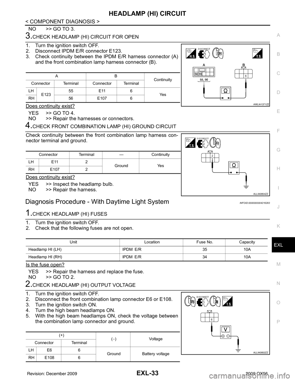
3.CHECK HEADLAMP (HI) CIRCUIT FOR OPEN
1. Turn the ignition switch OFF.
2. Disconnect IPDM E/R connector E123.
3. Check continuity between the IPDM E/R harness connector (A) and the front combination lamp harness connector (B).
Does continuity exist?
YES >> GO TO 4.
NO >> Repair the harnesses or connectors.
4.CHECK FRONT COMBINATION LAMP (HI) GROUND CIRCUIT
Check continuity between the front combination lamp harness con-
nector terminal and ground.
Does continuity exist?
YES >> Inspect the headlamp bulb.
NO >> Repair the harness.
Diagnosis Procedure - With Daytime Light SystemINFOID:0000000004216293
1.CHECK HEADLAMP (HI) FUSES
1. Turn the ignition switch OFF.
2. Check that the following fuses are not open.
Is the fuse open?
YES >> Repair the harness and replace the fuse.
NO >> GO TO 2.
2.CHECK HEADLAMP (HI) OUTPUT VOLTAGE
1. Turn the ignition switch OFF.
2. Disconnect the front combination lamp connector E6 or E108.
3. Turn the ignition switch ON.
4. Turn the high beam headlamps ON.
5. With the high beam headlamps ON, check the voltage between the combination lamp connector and ground.
AB Continuity
Connector Terminal Connector Terminal
LH E123 55
E11 6
Ye s
RH 56E107 6
AWLIA1371ZZ
Connector Terminal —Continuity
LH E11 2
Ground Yes
RH E107 2
ALLIA0854ZZ
Unit LocationFuse No.Capacity
Headlamp HI (LH) IPDM E/R3510A
Headlamp HI (RH) IPDM E/R3410A
(+)
(−)Voltage
Connector Terminal
LH E6 6 Ground Battery voltage
RH E108 6
ALLIA0852ZZ
Revision: December 20092009 QX56
Page 1982 of 4171
EXL-34
< COMPONENT DIAGNOSIS >
HEADLAMP (HI) CIRCUIT
Are the voltage readings as specified?
YES >> GO TO 4.
NO >> GO TO 3.
3.CHECK HEADLAMP (HI) CIRCUIT FOR OPEN
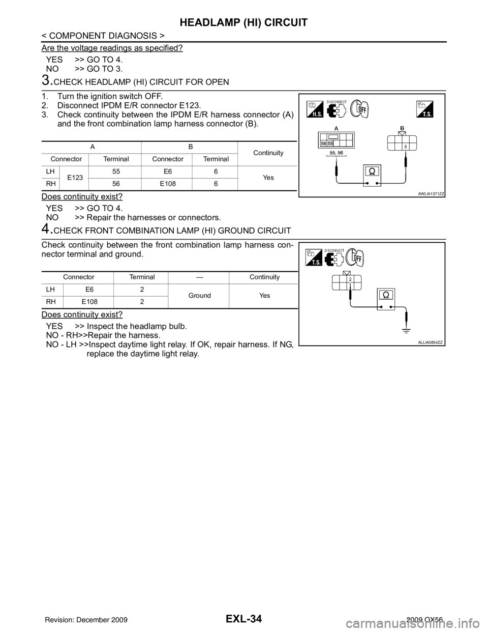
1. Turn the ignition switch OFF.
2. Disconnect IPDM E/R connector E123.
3. Check continuity between the IPDM E/R harness connector (A) and the front combination lamp harness connector (B).
Does continuity exist?
YES >> GO TO 4.
NO >> Repair the harnesses or connectors.
4.CHECK FRONT COMBINATION LAMP (HI) GROUND CIRCUIT
Check continuity between the front combination lamp harness con-
nector terminal and ground.
Does continuity exist?
YES >> Inspect the headlamp bulb.
NO - RH>>Repair the harness.
NO - LH >>Inspect daytime light rela y. If OK, repair harness. If NG,
replace the daytime light relay.
AB Continuity
Connector Terminal Connector Terminal
LH E123 55
E66
Ye s
RH 56E108 6
AWLIA1371ZZ
Connector Terminal —Continuity
LH E6 2
Ground Yes
RH E108 2
ALLIA0854ZZ
Revision: December 20092009 QX56
Page 1984 of 4171
EXL-36
< COMPONENT DIAGNOSIS >
HEADLAMP (LO) CIRCUIT
NO >> GO TO 3.
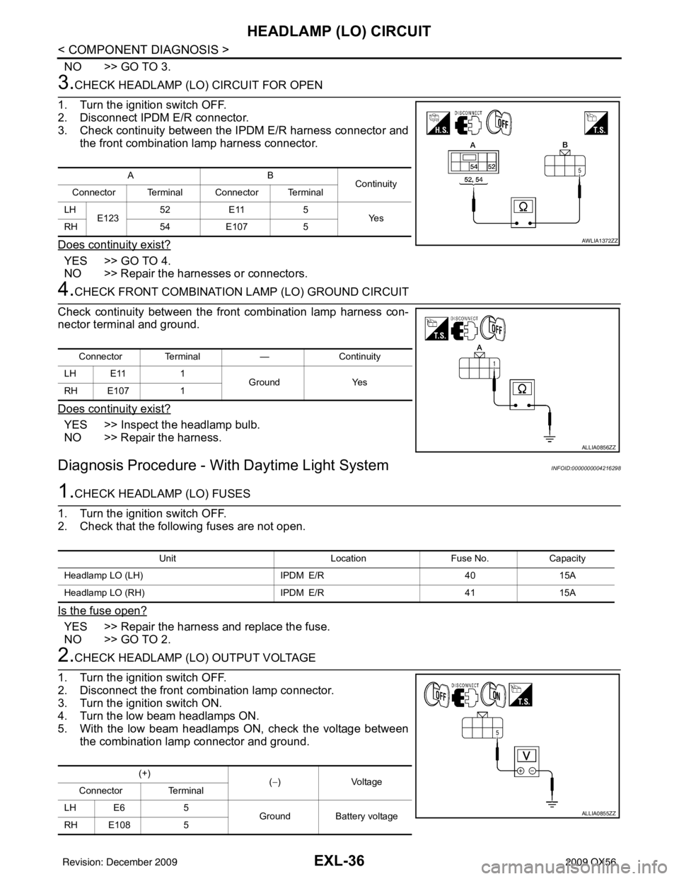
3.CHECK HEADLAMP (LO) CIRCUIT FOR OPEN
1. Turn the ignition switch OFF.
2. Disconnect IPDM E/R connector.
3. Check continuity between the IPDM E/R harness connector and
the front combination lamp harness connector.
Does continuity exist?
YES >> GO TO 4.
NO >> Repair the harnesses or connectors.
4.CHECK FRONT COMBINATION LAMP (LO) GROUND CIRCUIT
Check continuity between the front combination lamp harness con-
nector terminal and ground.
Does continuity exist?
YES >> Inspect the headlamp bulb.
NO >> Repair the harness.
Diagnosis Procedure - With Daytime Light SystemINFOID:0000000004216298
1.CHECK HEADLAMP (LO) FUSES
1. Turn the ignition switch OFF.
2. Check that the following fuses are not open.
Is the fuse open?
YES >> Repair the harness and replace the fuse.
NO >> GO TO 2.
2.CHECK HEADLAMP (LO) OUTPUT VOLTAGE
1. Turn the ignition switch OFF.
2. Disconnect the front combination lamp connector.
3. Turn the ignition switch ON.
4. Turn the low beam headlamps ON.
5. With the low beam headlamps ON, check the voltage between the combination lamp connector and ground.
AB Continuity
Connector Terminal Connector Terminal
LH E123 52
E11 5
Ye s
RH 54E107 5
AWLIA1372ZZ
Connector Terminal —Continuity
LH E11 1
Ground Yes
RH E107 1
ALLIA0856ZZ
Unit LocationFuse No.Capacity
Headlamp LO (LH) IPDM E/R4015A
Headlamp LO (RH) IPDM E/R4115A
(+)
(−)V olt a ge
Connector Terminal
LH E6 5
Ground Battery voltage
RH E108 5
ALLIA0855ZZ
Revision: December 20092009 QX56
Page 1985 of 4171
HEADLAMP (LO) CIRCUITEXL-37
< COMPONENT DIAGNOSIS >
C
DE
F
G H
I
J
K
M A
B
EXL
N
O P
Is voltage reading as specified?
YES >> GO TO 4.
NO >> GO TO 3.
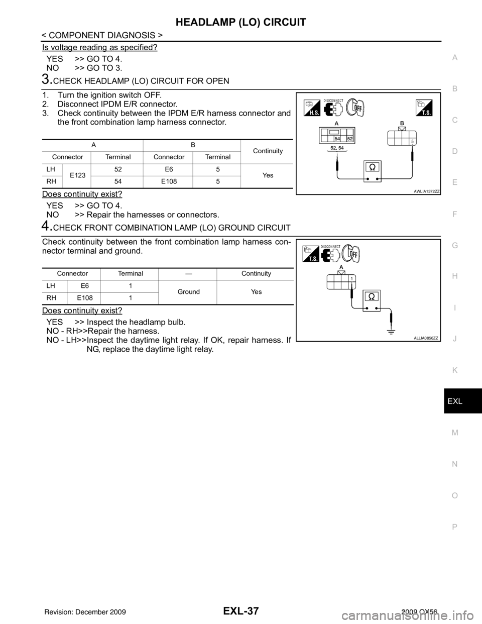
3.CHECK HEADLAMP (LO) CIRCUIT FOR OPEN
1. Turn the ignition switch OFF.
2. Disconnect IPDM E/R connector.
3. Check continuity between the IPDM E/R harness connector and the front combination lamp harness connector.
Does continuity exist?
YES >> GO TO 4.
NO >> Repair the harnesses or connectors.
4.CHECK FRONT COMBINATION LAMP (LO) GROUND CIRCUIT
Check continuity between the front combination lamp harness con-
nector terminal and ground.
Does continuity exist?
YES >> Inspect the headlamp bulb.
NO - RH>>Repair the harness.
NO - LH>>Inspect the daytime light relay. If OK, repair harness. If NG, replace the daytime light relay.
AB Continuity
Connector Terminal Connector Terminal
LH E123 52
E6 5
Ye s
RH 54E108 5
AWLIA1372ZZ
Connector Terminal —Continuity
LH E6 1
Ground Yes
RH E108 1
ALLIA0856ZZ
Revision: December 20092009 QX56
Page 1987 of 4171
FRONT FOG LAMP CIRCUITEXL-39
< COMPONENT DIAGNOSIS >
C
DE
F
G H
I
J
K
M A
B
EXL
N
O P
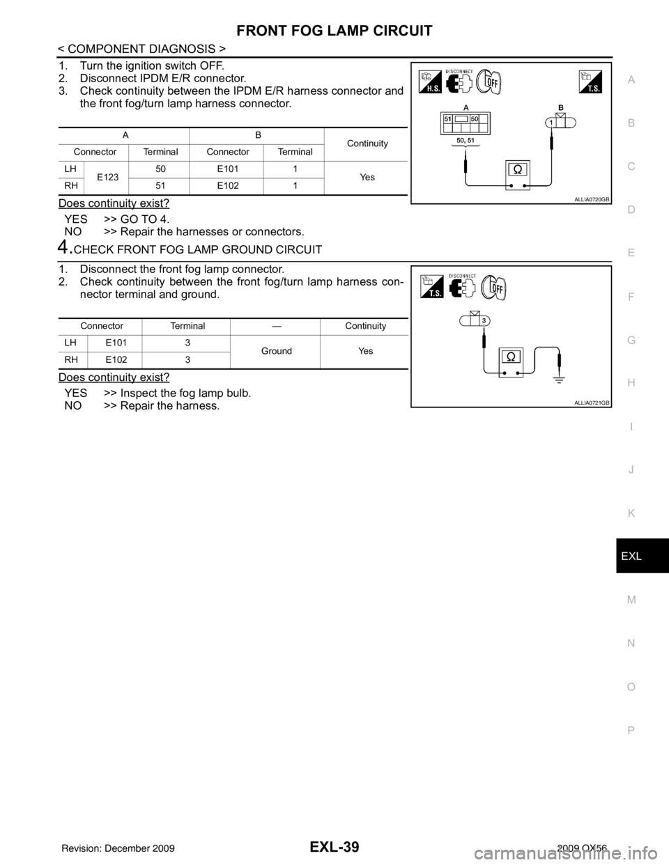
1. Turn the ignition switch OFF.
2. Disconnect IPDM E/R connector.
3. Check continuity between the IPDM E/R harness connector and the front fog/turn lamp harness connector.
Does continuity exist?
YES >> GO TO 4.
NO >> Repair the harnesses or connectors.
4.CHECK FRONT FOG LAMP GROUND CIRCUIT
1. Disconnect the front fog lamp connector.
2. Check continuity between the front fog/turn lamp harness con- nector terminal and ground.
Does continuity exist?
YES >> Inspect the fog lamp bulb.
NO >> Repair the harness.
AB Continuity
Connector Terminal Connector Terminal
LH E123 50
E101 1
Ye s
RH 51E102 1
ALLIA0720GB
Connector Terminal —Continuity
LH E101 3
Ground Yes
RH E102 3
ALLIA0721GB
Revision: December 20092009 QX56