spare wheel INFINITI QX56 2009 Factory Service Manual
[x] Cancel search | Manufacturer: INFINITI, Model Year: 2009, Model line: QX56, Model: INFINITI QX56 2009Pages: 4171, PDF Size: 84.65 MB
Page 5 of 4171
QUICK REFERNCE CHART: QX56
2010
Unit: mm (in)
*: Always check with the Parts Department for the latest parts information
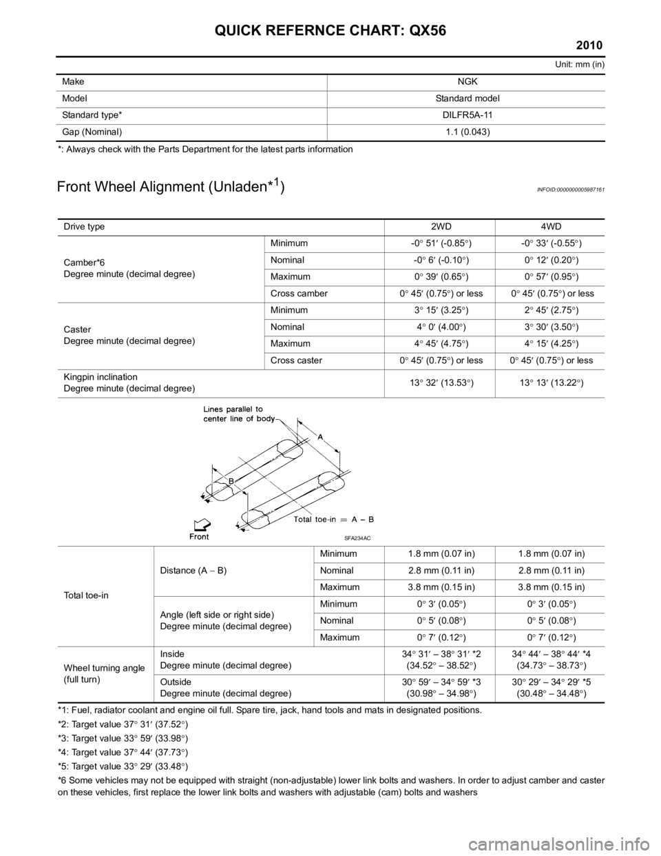
Front Wheel Alignment (Unladen*1)INFOID:0000000005987161
*1: Fuel, radiator coolant and engine oil full. Spare tire, jack, hand tools and mats in designated positions.
*2: Target value 37° 31 ′ (37.52 °)
*3: Target value 33 ° 59 ′ (33.98 °)
*4: Target value 37 ° 44 ′ (37.73 °)
*5: Target value 33 ° 29 ′ (33.48 °)
*6 Some vehicles may not be equipped with straight (non-adjustable) lower link bolts and washers. In order to adjust camber and caster
on these vehicles, first replace the lower link bolts and washers with adjustable (cam) bolts and washers Make
NGK
Model Standard model
Standard type* DILFR5A-11
Gap (Nominal) 1.1 (0.043)
Drive type2WD 4WD
Camber*6
Degree minute (decimal degree) Minimum -0
° 51 ′ (-0.85 °)-0 ° 33 ′ (-0.55 °)
Nominal -0 ° 6 ′ (-0.10 °)0 ° 12 ′ (0.20 °)
Maximum 0 ° 39 ′ (0.65 °)0 ° 57 ′ (0.95 °)
Cross camber 0 ° 45 ′ (0.75 °) or less 0 ° 45 ′ (0.75 °) or less
Caster
Degree minute (decimal degree) Minimum 3
° 15 ′ (3.25 °)2 ° 45 ′ (2.75 °)
Nominal 4 ° 0 ′ (4.00 °)3 ° 30 ′ (3.50 °)
Maximum 4 ° 45 ′ (4.75 °)4 ° 15 ′ (4.25 °)
Cross caster 0 ° 45 ′
(0.75 °) or less 0 ° 45 ′ (0.75 °) or less
Kingpin inclination
Degree minute (decimal degree) 13
° 32 ′ (13.53 °)13 ° 13 ′ (13.22 °)
Total toe-in Distance (A
− B) Minimum 1.8 mm (0.07 in) 1.8 mm (0.07 in)
Nominal 2.8 mm (0.11 in) 2.8 mm (0.11 in)
Maximum 3.8 mm (0.15 in) 3.8 mm (0.15 in)
Angle (left side or right side)
Degree minute (decimal degree) Minimum 0
° 3 ′ (0.05 °)0 ° 3 ′ (0.05 °)
Nominal 0 ° 5 ′ (0.08 °)0 ° 5 ′ (0.08 °)
Maximum 0 ° 7 ′ (0.12 °)0 ° 7 ′ (0.12 °)
Wheel turning angle
(full turn) Inside
Degree minute (decimal degree)
34
° 31 ′ – 38 ° 31 ′ *2
(34.52 ° – 38.52 °) 34
° 44 ′ – 38 ° 44 ′ *4
(34.73 ° – 38.73
° )
Outside
Degree minute (decimal degree) 30
° 59 ′ – 34 ° 59 ′ *3
(30.98 ° – 34.98 °) 30
° 29 ′ – 34 ° 29 ′ *5
(30.48 ° – 34.48 °)
SFA234AC
Page 6 of 4171
2009
QUICK REFERNCE CHART: QX56
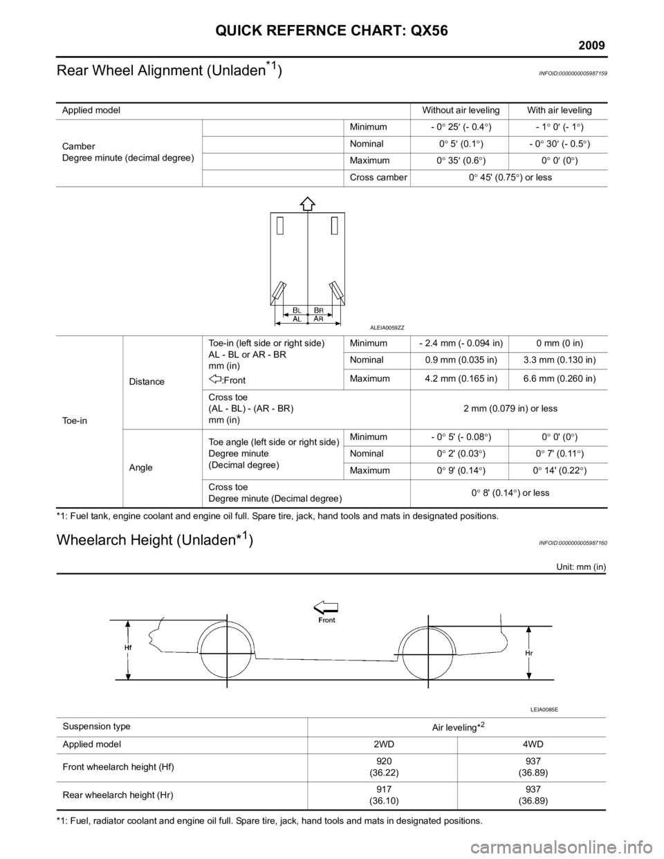
Rear Wheel Alignment (Unladen
*1)INFOID:0000000005987159
*1: Fuel tank, engine coolant and engine oil full. Spare tire, jack, hand tools and mats in designated positions.
Wheelarch Height (Unladen*1)INFOID:0000000005987160
Unit: mm (in)
*1: Fuel, radiator coolant and engine oil full. Spare tire, jack, hand tools and mats in designated positions. Applied model
Without air leveling With air leveling
Camber
Degree minute (decimal degree) Minimum - 0
° 25 ′ (- 0.4 °)- 1 ° 0 ′ (- 1 °)
Nominal 0 ° 5 ′ (0.1 °)- 0 ° 30 ′ (- 0.5 °)
Maximum 0 ° 35 ′ (0.6 °)0 ° 0 ′ (0 °)
Cross camber 0 ° 45' (0.75 °) or less
To e - i n Distance
Toe-in (left side or right side)
AL - BL or AR - BR
mm (in)
:Front Minimum - 2.4 mm (- 0.094 in) 0 mm (0 in)
Nominal 0.9 mm (0.035 in) 3.3 mm (0.130 in)
Maximum 4.2 mm (0.165 in) 6.6 mm (0.260 in)
Cross toe
(AL - BL) - (AR - BR)
mm (in) 2 mm (0.079 in) or less
Angle Toe angle (left side or right side)
Degree minute
(Decimal degree) Minimum - 0
° 5' (- 0.08 °)0 ° 0' (0 °)
Nominal 0 ° 2' (0.03 °)0 ° 7' (0.11 °)
Maximum 0 ° 9' (0.14 °)0 ° 14' (0.22 °)
Cross toe
Degree minute (Decimal degree) 0
° 8' (0.14 °) or less
ALEIA0059ZZ
Suspension type
Air leveling*2
Applied model 2WD 4WD
Front wheelarch height (Hf)920
(36.22) 937
(36.89)
Rear wheelarch height (Hr) 917
(36.10) 937
(36.89)
LEIA0085E
Page 2173 of 4171

PRECAUTIONSFSU-3
< PRECAUTION >
C
DF
G H
I
J
K L
M A
B
FSU
N
O P
5. When the repair work is completed, return the ignition switch to the ″LOCK ″ position before connecting
the battery cables. (At this time, the steering lock mechanism will engage.)
6. Perform a self-diagnosis check of al l control units using CONSULT-III.
PrecautionINFOID:0000000003772265
• When installing the rubber bushings, the final tightening must be done under unladen condition and with the
tires on level ground. Oil will shorten the life of the rubber bushings, so wipe off any spilled oil immediately.
• Unladen condition means the fuel tank, engine coolant and lubricants are at the full specification. The spare
tire, jack, hand tools, and mats are in their designated positions.
• After installing suspension components, check the wheel alignment.
• Lock nuts are not reusable. Always use new lock nuts for installation. New lock nuts are pre-oiled, do not
apply any additional lubrication.
Revision: December 20092009 QX56
Page 2176 of 4171
FSU-6
< ON-VEHICLE MAINTENANCE >
ON-VEHICLE SERVICE
ON-VEHICLE MAINTENANCE
ON-VEHICLE SERVICE
Front Suspension PartsINFOID:0000000003772269
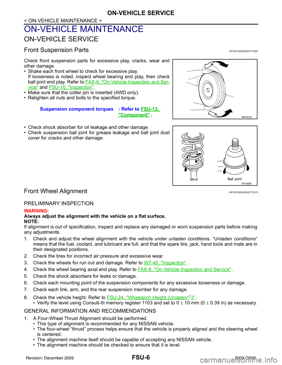
Check front suspension parts for excessive play, cracks, wear and
other damage.
• Shake each front wheel to check for excessive play.If looseness is noted, inspect wheel bearing end play, then check
ball joint end play. Refer to FA X - 6 , "
On-Vehicle Inspection and Ser-
vice" and FSU-10, "Inspection".
• Make sure that the cotter pin is inserted (4WD only).
• Retighten all nuts and bolts to the specified torque.
• Check shock absorber for oil leakage and other damage.
• Check suspension ball joint for grease leakage and ball joint dust cover for cracks and other damage.
Front Wheel AlignmentINFOID:0000000003772270
PRELIMINARY INSPECTION
WARNING:
Always adjust the alignment with the vehicle on a flat surface.
NOTE:
If alignment is out of specificat ion, inspect and replace any damaged or worn suspension parts before making
any adjustments.
1. Check and adjust the wheel alignment with the vehicle under unladen conditions. “Unladen conditions”
means that the fuel, coolant, and lubricant are full; and that the spare tire, jack, hand tools and mats are in
their designated positions.
2. Check the tires for incorrect air pressure and excessive wear.
3. Check the wheels for run out and damage. Refer to WT-40, "
Inspection" .
4. Check the wheel bearing axial end play. Refer to FA X - 6 , "
On-Vehicle Inspection and Service" .
5. Check the shock absorbers for leaks or damage.
6. Check each mounting point of the suspension components for any excessive looseness or damage.
7. Check each link, arm, and the rear suspension member for any damage.
8. Check the vehicle height. Refer to FSU-24, "
Wheelarch Height (Unladen*1)" .
• Verify the level using Consult-III memory register 1103 and set to 0 ± 10 mm (0 ± 0.39 in) as necessary.
GENERAL INFORMATION AND RECOMMENDATIONS
1. A Four-Wheel Thrust Alignment should be performed.
• This type of alignment is recommended for any NISSAN vehicle.
• The four-wheel “thrust” process helps ensure that the vehicle is properly aligned and the steering wheel
is centered.
• The alignment machine itself should be ca pable of accepting any NISSAN vehicle.
• The alignment machine should be checked to ensure that it is level. Suspension component
torques : Refer to FSU-13,
"Component" . SMA525A
SFA392B
Revision: December 20092009 QX56
Page 2193 of 4171
SERVICE DATA AND SPECIFICATIONS (SDS)FSU-23
< SERVICE DATA AND SPECIFICATIONS (SDS)
C
DF
G H
I
J
K L
M A
B
FSU
N
O P
SERVICE DATA AND SPECIFICATIONS (SDS)
SERVICE DATA AND SPECIFICATIONS (SDS)
General SpecificationINFOID:0000000003772281
Spring Free HeightINFOID:0000000003772282
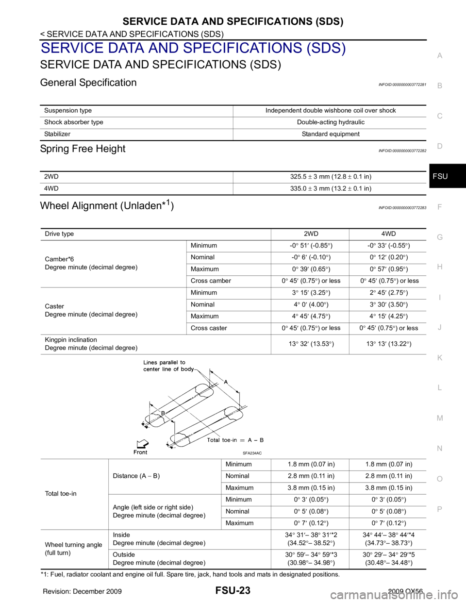
Wheel Alignment (Unladen*1)INFOID:0000000003772283
*1: Fuel, radiator coolant and engine oil full. Spare tire, jack, hand tools and mats in designated positions. Suspension type
Independent double wishbone coil over shock
Shock absorber type Double-acting hydraulic
Stabilizer Standard equipment
2WD325.5 ± 3 mm (12.8 ± 0.1 in)
4WD 335.0 ± 3 mm (13.2 ± 0.1 in)
Drive type 2WD 4WD
Camber*6
Degree minute (decimal degree) Minimum
-0° 51 ′ (-0.85 °)- 0° 33 ′ (-0.55 °)
Nominal -0° 6 ′ (-0.10 °)0 ° 12 ′ (0.20 °)
Maximum 0° 39 ′ (0.65 °)0 ° 57 ′ (0.95 °)
Cross camber 0° 45 ′ (0.75 °) or less 0 ° 45′ (0.75 °) or less
Caster
Degree minute (decimal degree) Minimum
3° 15 ′ (3.25 °)2 ° 45 ′ (2.75 °)
Nominal 4° 0 ′ (4.00 °)3 ° 30 ′ (3.50 °)
Maximum 4° 45 ′ (4.75 °)4 ° 15 ′ (4.25 °)
Cross caster 0° 45 ′ (0.75 °) or less 0
° 45 ′ (0
.75°) or less
Kingpin inclination
Degree minute (decimal degree) 13
° 32 ′ (13.53 °)1 3° 13 ′ (13.22 °)
Total toe-in Distance (A
− B) Minimum
1.8 mm (0.07 in) 1.8 mm (0.07 in)
Nominal 2.8 mm (0.11 in) 2.8 mm (0.11 in)
Maximum 3.8 mm (0.15 in) 3.8 mm (0.15 in)
Angle (left side or right side)
Degree minute (decimal degree) Minimum
0° 3 ′ (0.05 °)0 ° 3 ′ (0.05 °)
Nominal 0° 5 ′ (0.08 °)0 ° 5 ′ (0.08 °)
Maximum 0° 7 ′ (0.12 °)0 ° 7 ′ (0.12 °)
Wheel turning angle
(full turn) Inside
Degree minute (decimal degree)
34
° 31 ′– 38 ° 31 ′*2
(34.52 °– 38.52° ) 34
° 44 ′– 38° 44′*4
(34.73 °– 38.73 °)
Ou t
side
Degree minute (decimal degree) 30
° 59 ′– 34 ° 59 ′*3
(30.98 °– 34.98° ) 30
° 29 ′– 34° 29′*5
(30.48 °– 34.48 °)
SFA234AC
Revision: December 20092009 QX56
Page 2194 of 4171
FSU-24
< SERVICE DATA AND SPECIFICATIONS (SDS)
SERVICE DATA AND SPECIFICATIONS (SDS)
*2: Target value 37° 31 ′ (37.52 °)
*3: Target value 33 ° 59 ′ (33.98 °)
*4: Target value 37 ° 44 ′ (37.73 °)
*5: Target value 33 ° 29 ′ (33.48 °)
*6 Some vehicles may not be equipped with straight (non-adjustable) lower link bolts and washers. In order to adjust camber and caster
on these vehicles, first replace the lower link bolts and washers with adjustable (cam) bolts and washers
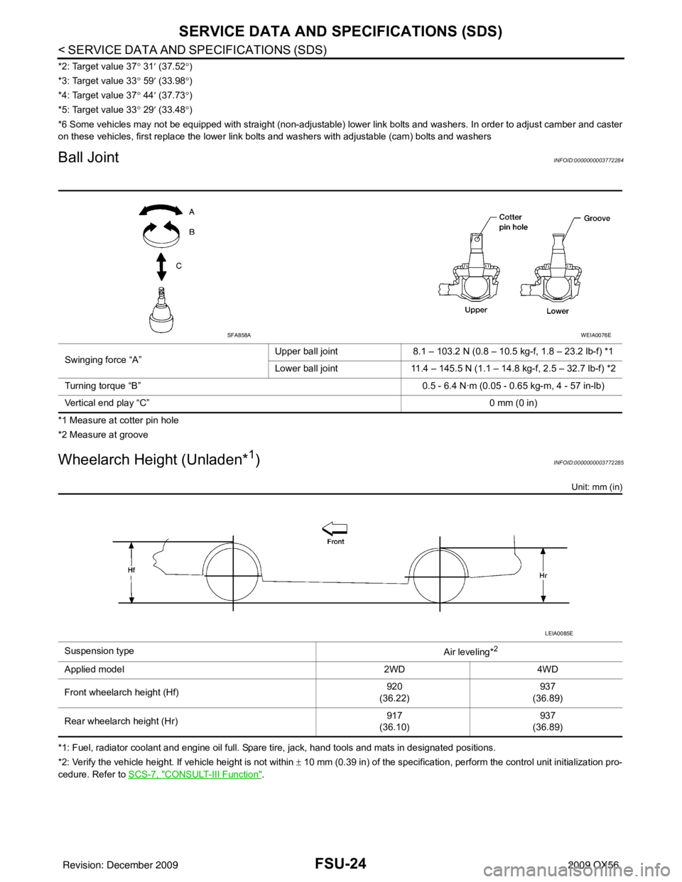
Ball JointINFOID:0000000003772284
*1 Measure at cotter pin hole
*2 Measure at groove
Wheelarch Height (Unladen*1)INFOID:0000000003772285
Unit: mm (in)
*1: Fuel, radiator coolant and engine oil full. Spare tire, jack, hand tools and mats in designated positions.
*2: Verify the vehicle height. If vehicle height is not within ± 10 mm (0.39 in) of the specification, perform the control unit initialization pro-
cedure. Refer to SCS-7, "
CONSULT-III Function".
Swinging force “A”
Upper ball joint
8.1 – 103.2 N (0.8 – 10.5 kg-f, 1.8 – 23.2 lb-f) *1
Lower ball joint 11.4 – 145.5 N (1.1 – 14.8 kg-f, 2.5 – 32.7 lb-f) *2
Turning torque “B” 0.5 - 6.4 N·m (0.05 - 0.65 kg-m, 4 - 57 in-lb)
Vertical end play “C” 0 mm (0 in)
SFA858AWEIA0076E
Suspension type
Air leveling*2
Applied model2WD4WD
Front wheelarch height (Hf) 920
(36.22) 937
(36.89)
Rear wheelarch height (Hr) 917
(36.10) 937
(36.89)
LEIA0085E
Revision: December 20092009 QX56
Page 2217 of 4171

IDENTIFICATION INFORMATIONGI-23
< FEATURES OF NEW MODEL >
C
DE
F
G H
I
J
K L
M B
GI
N
O P
DimensionsINFOID:0000000003771193
Unit: mm (in)
Wheels & TiresINFOID:0000000003771194
* With Steel Wheel Drive type
2WD4WD
Overall length 5254 (206.9)5255 (206.9)
Overall width 2001 (78.8)2001 (78.8)
Overall height (with roof rack) 1976.8 (77.8)1997.7 (78.7)
Front tread width 1715 (67.5)1715 (67.5)
Rear tread width 1715 (67.5)1715 (67.5)
Wheelbase 3130 (123.2)3130 (123.2)
Minimum Running Ground Clearance (at front suspension) 211.2 (8.3)232 (9.1)
Drive Type Grade Road wheelTireSpare tire size*
All QX56 20x8JJ Chromium Aluminum Alloy P275/60R20P275/60R20
Revision: December 20092009 QX56
Page 2303 of 4171

LOW-PRESSURE PIPEHA-39
< ON-VEHICLE REPAIR >
C
DE
F
G H
J
K L
M A
B
HA
N
O P
5. Remove the front and rear bumper fascia. Refer to EXT-13, "Removal and Installation" (front), EXT-15,
"Removal and Installation" (rear).
6. Reposition the front fender protec tor out of the way. Refer to EXT-23, "Removal and Installation"
.
7. Disconnect the chassis harness connector.
8. Remove the spare wheel and tire.
9. Remove the tailpipe and tailpipe hanger bracket. Refer to EX-6, "Removal and Installation"
.
10. Remove the seatbelt latch anchor. Refer to EX-6, "Removal and Installation"
.
11. Remove the front floor heat shield.
12. Disconnect each end of the underfloor rear high- and low-pressure A/C and heater core pipes. Refer to
HA-29, "Component"
.
CAUTION:
Cap or wrap the joint of the pipes with suitable material such as viny l tape to avoid the entry of air.
13. Set two suitable jacks at the RH body mount points to support the vehicle body when it is separated from the RH side of the frame.
14. Remove the RH body mount bolts. Refer to BRM-6, "Body Mounting"
.
15. Use the vehicle hoist to lower the RH side of the frame from the RH side of the body [approximately 305
mm (12 in)] until there is suffici ent clearance to remove the underfloor rear high- and low-pressure A/C
and heater core pipes from between the body and the frame.
16. Remove the underfloor rear high- and low-pressure A/ C and heater core pipes from the back of the vehi-
cle.
INSTALLATION
Installation is in the reverse order of removal.
CAUTION:
Replace the O-rings of the underfloor rear high - and low-pressure A/C and heater core pipes with
new ones, then apply compressor oil to them for installation.
After charging refrigerant, check for leaks.
Revision: December 20092009 QX56
Page 2307 of 4171

HIGH-PRESSURE PIPEHA-43
< ON-VEHICLE REPAIR >
C
DE
F
G H
J
K L
M A
B
HA
N
O P
5. Remove the front and rear bumper fascia. Refer to EXT-13, "Removal and Installation" (front), EXT-15,
"Removal and Installation" (rear).
6. Reposition the front fender protec tor out of the way. Refer to EXT-23, "Removal and Installation"
.
7. Disconnect the chassis harness connector.
8. Remove the spare wheel and tire.
9. Remove the tailpipe and tailpipe hanger bracket. Refer to EX-6, "Removal and Installation"
.
10. Remove the seatbelt latch anchor. Refer to EX-6, "Removal and Installation"
.
11. Remove the front floor heat shield.
12. Disconnect each end of the underfloor rear high- and low-pressure A/C and heater core pipes. Refer to
HA-29, "Component"
.
CAUTION:
Cap or wrap the joint of the pipes with suitable material such as viny l tape to avoid the entry of air.
13. Set two suitable jacks at the RH body mount points to support the vehicle body when it is separated from the RH side of the frame.
14. Remove the RH body mount bolts. Refer to BRM-6, "Body Mounting"
.
15. Use the vehicle hoist to lower the RH side of the frame from the RH side of the body [approximately 305
mm (12 in)] until there is suffici ent clearance to remove the underfloor rear high- and low-pressure A/C
and heater core pipes from between the body and the frame.
16. Remove the underfloor rear high- and low-pressure A/ C and heater core pipes from the back of the vehi-
cle.
INSTALLATION
Installation is in the reverse order of removal.
CAUTION:
Replace the O-rings of the underfloor rear high - and low-pressure A/C and heater core pipes with
new ones, then apply compressor oil to them for installation.
After charging refrigerant, check for leaks.
Revision: December 20092009 QX56
Page 2702 of 4171
CHASSIS AND BODY MAINTENANCEMA-29
< ON-VEHICLE MAINTENANCE >
C
DE
F
G H
I
J
K L
M B
MA
N
O A
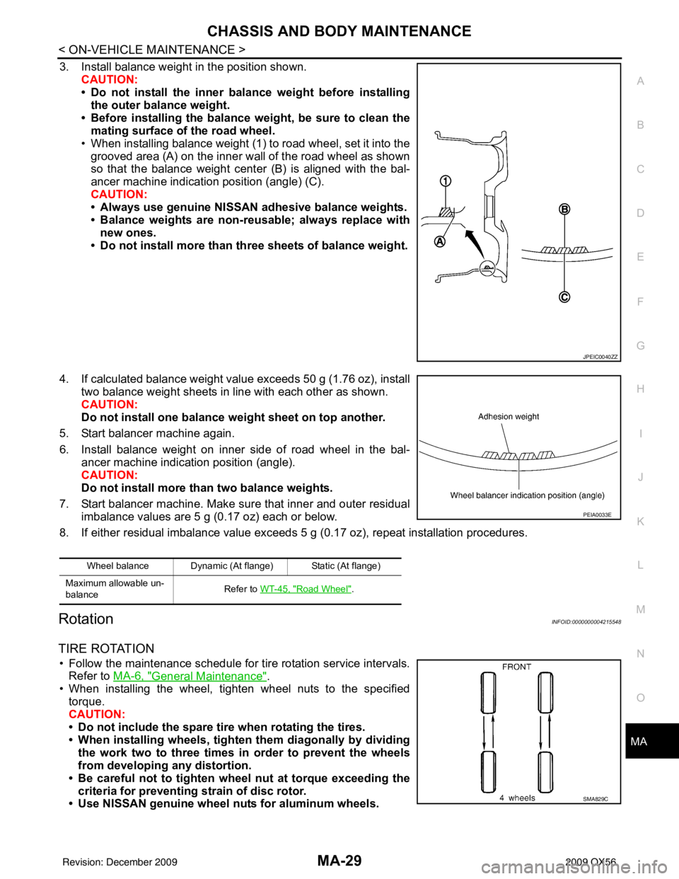
3. Install balance weight in the position shown.
CAUTION:
• Do not install the inner bala nce weight before installing
the outer balance weight.
• Before installing the balance weight, be sure to clean the mating surface of the road wheel.
• When installing balance weight (1) to road wheel, set it into the grooved area (A) on the inner wall of the road wheel as shown
so that the balance weight cent er (B) is aligned with the bal-
ancer machine indication position (angle) (C).
CAUTION:
• Always use genuine NISSAN adhesive balance weights.
• Balance weights are non-re usable; always replace with
new ones.
• Do not install more than th ree sheets of balance weight.
4. If calculated balance weight value exceeds 50 g (1.76 oz), install two balance weight sheets in line with each other as shown.
CAUTION:
Do not install one balance weight sheet on top another.
5. Start balancer machine again.
6. Install balance weight on inner side of road wheel in the bal- ancer machine indication position (angle).
CAUTION:
Do not install more than two balance weights.
7. Start balancer machine. Make sure that inner and outer residual imbalance values are 5 g (0.17 oz) each or below.
8. If either residual imbalance value exceeds 5 g (0.17 oz), repeat installation procedures.
RotationINFOID:0000000004215548
TIRE ROTATION
• Follow the maintenance schedule for tire rotation service intervals.
Refer to MA-6, "
General Maintenance".
• When installing the wheel, tighten wheel nuts to the specified
torque.
CAUTION:
• Do not include the spare tire when rotating the tires.
• When installing wheels, tighte n them diagonally by dividing
the work two to three times in order to prevent the wheels
from developing any distortion.
• Be careful not to tighten wh eel nut at torque exceeding the
criteria for preventing strain of disc rotor.
• Use NISSAN genuine wheel nuts for aluminum wheels.
JPEIC0040ZZ
Wheel balance Dynamic (At flange) Static (At flange)
Maximum allowable un-
balance Refer to WT-45, "
Road Wheel".
PEIA0033E
SMA829C
Revision: December 20092009 QX56