torque INFINITI QX56 2010 Factory Service Manual
[x] Cancel search | Manufacturer: INFINITI, Model Year: 2010, Model line: QX56, Model: INFINITI QX56 2010Pages: 4210, PDF Size: 81.91 MB
Page 2607 of 4210
![INFINITI QX56 2010 Factory Service Manual LAN
TROUBLE DIAGNOSISLAN-9
< FUNCTION DIAGNOSIS > [CAN FUNDAMENTAL]
C
D
E
F
G H
I
J
K L
B A
O P
N
NOTE:
• When data link connector branch line is open, transmi
ssion and reception of CAN communicati INFINITI QX56 2010 Factory Service Manual LAN
TROUBLE DIAGNOSISLAN-9
< FUNCTION DIAGNOSIS > [CAN FUNDAMENTAL]
C
D
E
F
G H
I
J
K L
B A
O P
N
NOTE:
• When data link connector branch line is open, transmi
ssion and reception of CAN communicati](/img/42/57032/w960_57032-2606.png)
LAN
TROUBLE DIAGNOSISLAN-9
< FUNCTION DIAGNOSIS > [CAN FUNDAMENTAL]
C
D
E
F
G H
I
J
K L
B A
O P
N
NOTE:
• When data link connector branch line is open, transmi
ssion and reception of CAN communication signals
are not affected. Therefore, no symptoms occur. However, be sure to repair malfunctioning circuit.
• When data link connector branch line is open, “ECU list ” displayed on the CONSULT-III “CAN DIAG SUP-
PORT MNTR” may be the same as when the CAN comm unication line has short-circuit. However, symp-
toms differ depending on the case. See below chart for the differences.
Example: Main Line Between Data Link Connector and ABS Actuator and Electr ic Unit (Control Unit) Open Circuit
Unit name Symptom
ECM
Normal operation.
BCM
EPS control unit
Combination meter
ABS actuator and electric
unit (control unit)
TCM
IPDM E/R
“ECU list” on the “CAN DIAG SUPPORT MNTR”(CONSULT-III) Difference of symptom
Data link connector branch line open circuit All Diag on CAN units are not
indicated.Normal operation.
CAN-H, CAN-L harness short-circuit Most of the units which are connected to the CAN
communication system enter fail-safe mode or are
deactivated.
SKIB8740E
Unit name
Symptom
ECM Engine torque limiting is affected, and shift harshness increases.
BCM • Reverse warning chime does not sound.
• The front wiper moves under continuous operation mode even though the front wip-
er switch being in the intermittent position.
EPS control unit The steering effort increases.
Combination meter • The shift position indicator and OD OFF indicator turn OFF.
• The speedometer is inoperative.
• The odo/trip meter stops.
ABS actuator and electric unit (control unit) Normal operation.
Revision: April 20092010 QX56
Page 2608 of 4210
![INFINITI QX56 2010 Factory Service Manual LAN-10
< FUNCTION DIAGNOSIS >[CAN FUNDAMENTAL]
TROUBLE DIAGNOSIS
Example: CAN-H, CAN-L Harness Short Circuit
TCM
No impact on operation.
IPDM E/R When the ignition switch is ON,
• The headlamps (Lo) INFINITI QX56 2010 Factory Service Manual LAN-10
< FUNCTION DIAGNOSIS >[CAN FUNDAMENTAL]
TROUBLE DIAGNOSIS
Example: CAN-H, CAN-L Harness Short Circuit
TCM
No impact on operation.
IPDM E/R When the ignition switch is ON,
• The headlamps (Lo)](/img/42/57032/w960_57032-2607.png)
LAN-10
< FUNCTION DIAGNOSIS >[CAN FUNDAMENTAL]
TROUBLE DIAGNOSIS
Example: CAN-H, CAN-L Harness Short Circuit
TCM
No impact on operation.
IPDM E/R When the ignition switch is ON,
• The headlamps (Lo) turn ON.
• The cooling fan continues to rotate.
Unit name
Symptom
SKIB8741E
Unit nameSymptom
ECM • Engine torque limiting is affected, and shift harshness increases.
• Engine speed drops.
BCM • Reverse warning chime does not sound.
• The front wiper moves under continuous operation mode even though the front
wiper switch being in the intermittent position.
• The room lamp does not turn ON.
• The engine does not start (if an error or malfunction occurs while turning the igni- tion switch OFF.)
• The steering lock does not release (if an error or malfunction occurs while turning the ignition switch OFF.)
EPS control unit The steering effort increases.
Combination meter • The tachometer and the speedometer do not move.
• Warning lamps turn ON.
• Indicator lamps do not turn ON.
ABS actuator and electric unit (control unit) Normal operation.
TCM No impact on operation.
IPDM E/R When the ignition switch is ON,
• The headlamps (Lo) turn ON.
• The cooling fan continues to rotate.
Revision: April 20092010 QX56
Page 2695 of 4210
ENGINE OILLU-9
< ON-VEHICLE MAINTENANCE >
C
DE
F
G H
I
J
K L
M A
LU
NP
O
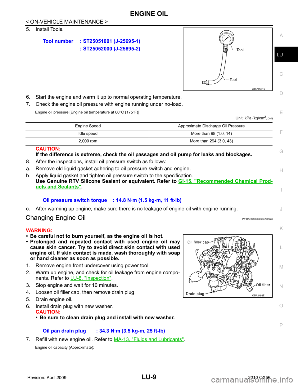
5. Install Tools.
6. Start the engine and warm it up to normal operating temperature.
7. Check the engine oil pressure with engine running under no-load.
Engine oil pressure [Engine oil temperature at 80
°C (175 °F)]
Unit: kPa (kg/cm2, psi)
CAUTION:
If the difference is extreme, check the oil passages and oil pump for leaks and blockages.
8. After the inspections, install oil pressure switch as follows:
a. Remove old liquid gasket adhering to oil pressure switch and engine.
b. Apply liquid gasket and tighten oil pressure switch to the specification. Use Genuine RTV Silicone Seal ant or equivalent. Refer to GI-15, "
Recommended Chemical Prod-
ucts and Sealants".
c. After warming up engine, make sure there is no leakage of engine oil with engine running.
Changing Engine OilINFOID:0000000005149026
WARNING:
• Be careful not to burn yourself, as the engine oil is hot.
• Prolonged and repeated contact with used engine oil may cause skin cancer. Try to avoid direct skin contact with used
engine oil. If skin contact is made, wash thoroughly with soap
or hand cleaner as soon as possible.
1. Remove engine front undercover using power tool.
2. Warm up engine, and check for oil leakage from engine compo- nents. Refer to LU-8, "
Inspection".
3. Stop engine and wait for 10 minutes.
4. Loosen oil filler cap, then remove drain plug.
5. Drain engine oil.
6. Install drain plug with new washer. CAUTION:
• Be sure to clean drain plug and install with new washer.
7. Refill with new engine oil. Refer to MA-13, "
Fluids and Lubricants".
Engine oil capacity (Approximate):
Tool number : ST25051001 (J-25695-1)
: ST25052000 (J-25695-2)
WBIA0571E
Engine Speed Approximate Discharge Oil Pressure
Idle speed More than 98 (1.0, 14)
2,000 rpm More than 294 (3.0, 43)
Oil pressure switch torque : 14.8 N·m (1.5 kg-m, 11 ft-lb)
Oil pan drain plug : 34.3 N·m (3.5 kg-m, 25 ft-lb)
KBIA2498E
Revision: April 20092010 QX56
Page 2726 of 4210
MA-22
< ON-VEHICLE MAINTENANCE >
ENGINE MAINTENANCE
8. After the inspections, install oil pressure switch as follows:
a. Remove old liquid gasket adhering to oil pressure switch and engine.
b. Apply liquid gasket and tighten oil pressure switch to the specification.Use Genuine RTV Silicone Seal ant or equivalent. Refer to GI-15, "
Recommended Chemical Prod-
ucts and Sealants".
c. After warming up engine, make sure there is no leakage of engine oil with engine running.
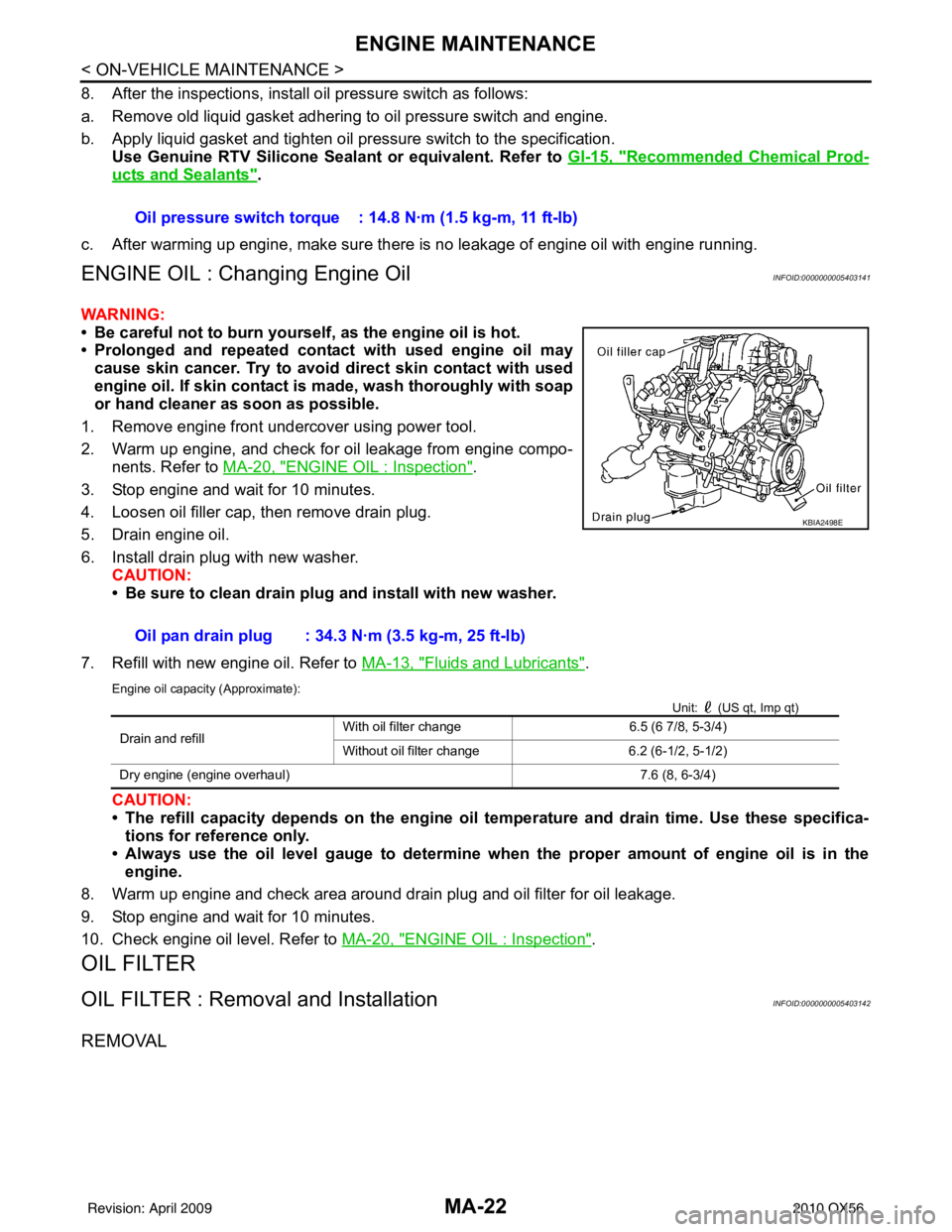
ENGINE OIL : Changing Engine OilINFOID:0000000005403141
WARNING:
• Be careful not to burn yoursel f, as the engine oil is hot.
• Prolonged and repeated contact with used engine oil may
cause skin cancer. Try to avoid di rect skin contact with used
engine oil. If skin contact is made, wash thoroughly with soap
or hand cleaner as soon as possible.
1. Remove engine front undercover using power tool.
2. Warm up engine, and check for oil leakage from engine compo- nents. Refer to MA-20, "
ENGINE OIL : Inspection".
3. Stop engine and wait for 10 minutes.
4. Loosen oil filler cap, then remove drain plug.
5. Drain engine oil.
6. Install drain plug with new washer. CAUTION:
• Be sure to clean drain plug and install with new washer.
7. Refill with new engine oil. Refer to MA-13, "
Fluids and Lubricants".
Engine oil capacity (Approximate):
Unit: (US qt, Imp qt)
CAUTION:
• The refill capacity depends on the engine oil temperature and drain time. Use these specifica-
tions for reference only.
• Always use the oil level gauge to determine when the proper amount of engine oil is in the engine.
8. Warm up engine and check area around drain plug and oil filter for oil leakage.
9. Stop engine and wait for 10 minutes.
10. Check engine oil level. Refer to MA-20, "
ENGINE OIL : Inspection".
OIL FILTER
OIL FILTER : Removal and InstallationINFOID:0000000005403142
REMOVAL
Oil pressure switch torque : 14.8 N·m (1.5 kg-m, 11 ft-lb)
Oil pan drain plug : 34.3 N·m (3.5 kg-m, 25 ft-lb)
KBIA2498E
Drain and refill With oil filter change
6.5 (6 7/8, 5-3/4)
Without oil filter change 6.2 (6-1/2, 5-1/2)
Dry engine (engine overhaul) 7.6 (8, 6-3/4)
Revision: April 20092010 QX56
Page 2734 of 4210
MA-30
< ON-VEHICLE MAINTENANCE >
CHASSIS AND BODY MAINTENANCE
TRANSFER FLUID
TRANSFER FLUID : ReplacementINFOID:0000000005403153
CAUTION:
If using the vehicle for towing, the transfer fluid must be replaced as specified. Refer to MA-9, "
Intro-
duction of Periodic Maintenance".
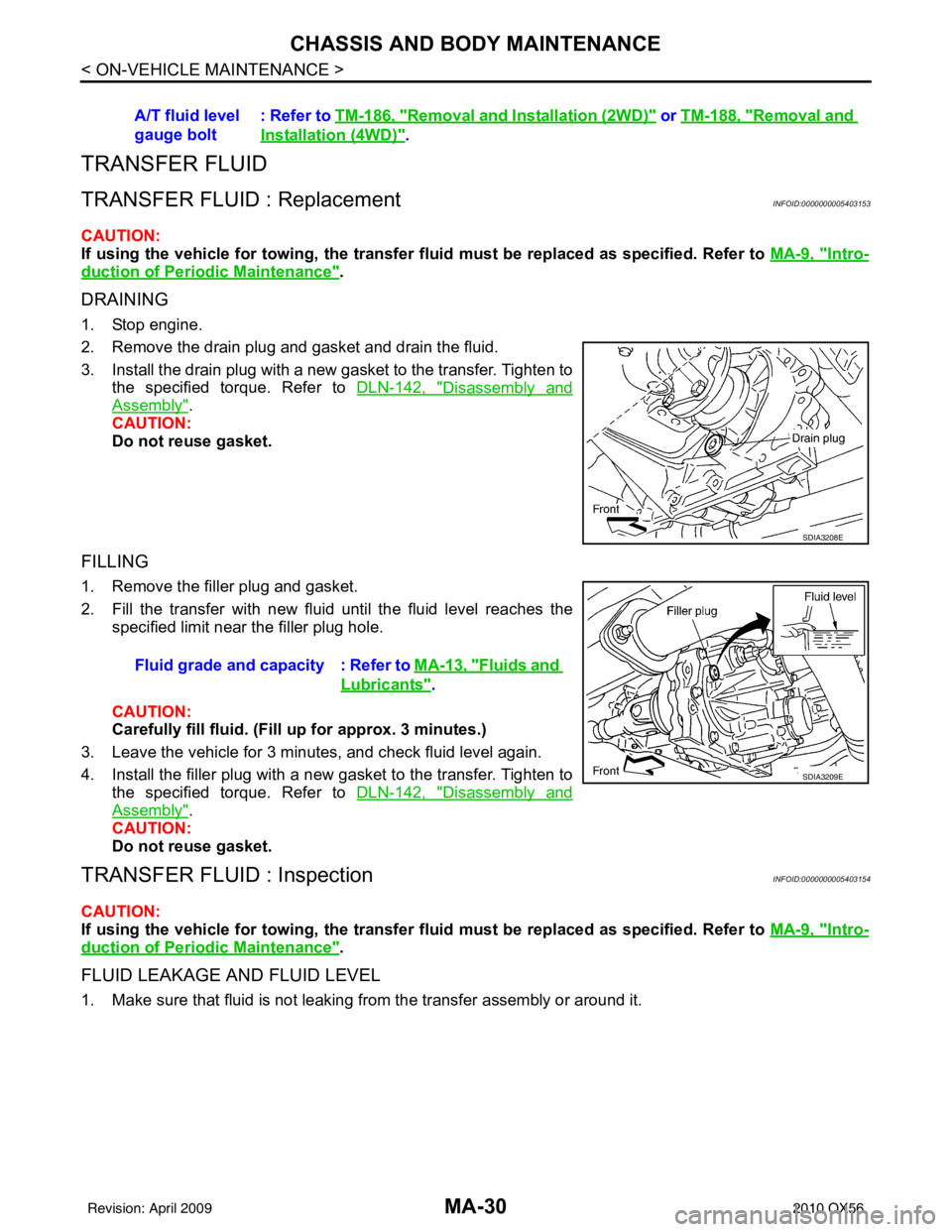
DRAINING
1. Stop engine.
2. Remove the drain plug and gasket and drain the fluid.
3. Install the drain plug with a new gasket to the transfer. Tighten to
the specified torque. Refer to DLN-142, "
Disassembly and
Assembly".
CAUTION:
Do not reuse gasket.
FILLING
1. Remove the filler plug and gasket.
2. Fill the transfer with new fluid until the fluid level reaches the specified limit near the filler plug hole.
CAUTION:
Carefully fill fluid. (Fil l up for approx. 3 minutes.)
3. Leave the vehicle for 3 minutes, and check fluid level again.
4. Install the filler plug with a new gasket to the transfer. Tighten to the specified torque. Refer to DLN-142, "
Disassembly and
Assembly".
CAUTION:
Do not reuse gasket.
TRANSFER FLUID : InspectionINFOID:0000000005403154
CAUTION:
If using the vehicle for towing, the transfer fluid must be replaced as specified. Refer to MA-9, "
Intro-
duction of Periodic Maintenance".
FLUID LEAKAGE AND FLUID LEVEL
1. Make sure that fluid is not leaking from the transfer assembly or around it.A/T fluid level
gauge bolt
: Refer to
TM-186, "
Removal and Installation (2WD)" or TM-188, "Removal and
Installation (4WD)".
SDIA3208E
Fluid grade and capacity : Refer to MA-13, "Fluids and
Lubricants".
SDIA3209E
Revision: April 20092010 QX56
Page 2735 of 4210
CHASSIS AND BODY MAINTENANCEMA-31
< ON-VEHICLE MAINTENANCE >
C
DE
F
G H
I
J
K L
M B
MA
N
O A
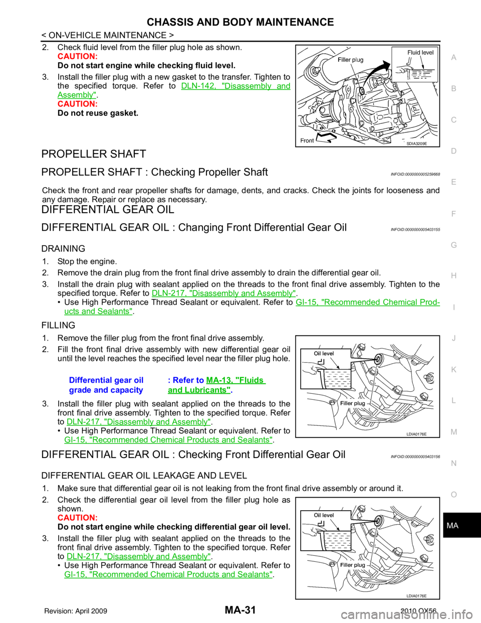
2. Check fluid level from the filler plug hole as shown.
CAUTION:
Do not start engine while checking fluid level.
3. Install the filler plug with a new gasket to the transfer. Tighten to the specified torque. Refer to DLN-142, "
Disassembly and
Assembly".
CAUTION:
Do not reuse gasket.
PROPELLER SHAFT
PROPELLER SHAFT : Checking Propeller ShaftINFOID:0000000005259668
Check the front and rear propeller shafts for damage, dents, and cracks. Check the joints for looseness and
any damage. Repair or replace as necessary.
DIFFERENTIAL GEAR OIL
DIFFERENTIAL GEAR OIL : Changing Front Differential Gear OilINFOID:0000000005403155
DRAINING
1. Stop the engine.
2. Remove the drain plug from the front final drive assembly to drain the differential gear oil.
3. Install the drain plug with sealant applied on the thr eads to the front final drive assembly. Tighten to the
specified torque. Refer to DLN-217, "
Disassembly and Assembly".
• Use High Performance Thread Sealant or equivalent. Refer to GI-15, "
Recommended Chemical Prod-
ucts and Sealants".
FILLING
1. Remove the filler plug from the front final drive assembly.
2. Fill the front final drive assembly with new differential gear oil
until the level reaches the specified level near the filler plug hole.
3. Install the filler plug with sealant applied on the threads to the front final drive assembly. Tighten to the specified torque. Refer
to DLN-217, "
Disassembly and Assembly".
• Use High Performance Thread Sealant or equivalent. Refer to GI-15, "
Recommended Chemical Products and Sealants".
DIFFERENTIAL GEAR OIL : Checking Front Differential Gear OilINFOID:0000000005403156
DIFFERENTIAL GEAR OIL LEAKAGE AND LEVEL
1. Make sure that differential gear oil is not leaking from the front final drive assembly or around it.
2. Check the differential gear oil level from the filler plug hole as
shown.
CAUTION:
Do not start engine while checki ng differential gear oil level.
3. Install the filler plug with sealant applied on the threads to the front final drive assembly. Tighten to the specified torque. Refer
to DLN-217, "
Disassembly and Assembly".
• Use High Performance Thread Sealant or equivalent. Refer to GI-15, "
Recommended Chemical Products and Sealants".
SDIA3209E
Differential gear oil
grade and capacity : Refer to
MA-13, "Fluids
and Lubricants".
LDIA0176E
LDIA0176E
Revision: April 20092010 QX56
Page 2736 of 4210
MA-32
< ON-VEHICLE MAINTENANCE >
CHASSIS AND BODY MAINTENANCE
DIFFERENTIAL GEAR OIL : Changi ng Rear Differential Gear Oil
INFOID:0000000005403157
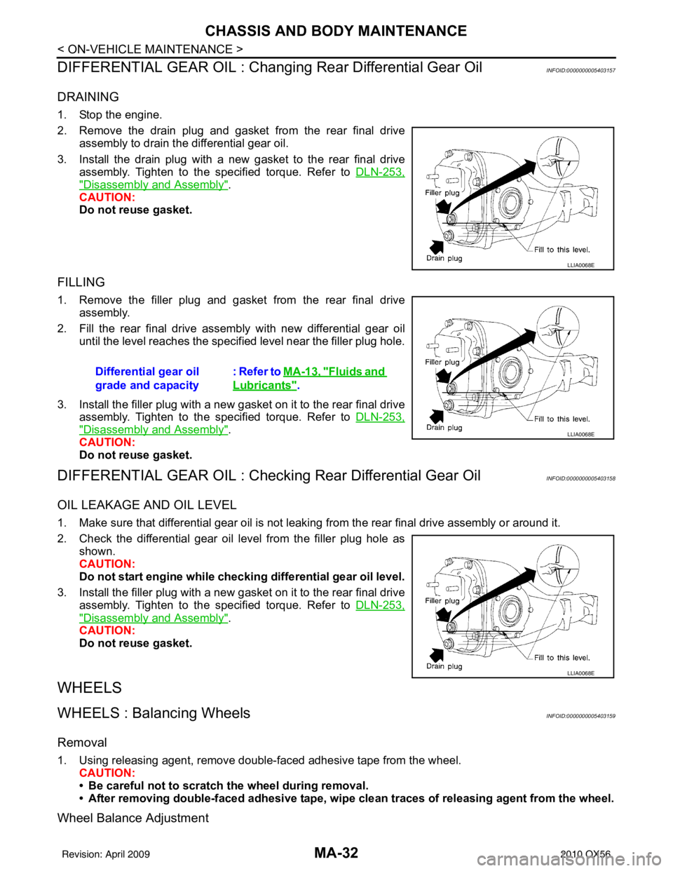
DRAINING
1. Stop the engine.
2. Remove the drain plug and gasket from the rear final drive
assembly to drain the differential gear oil.
3. Install the drain plug with a new gasket to the rear final drive assembly. Tighten to the specified torque. Refer to DLN-253,
"Disassembly and Assembly".
CAUTION:
Do not reuse gasket.
FILLING
1. Remove the filler plug and gasket from the rear final drive assembly.
2. Fill the rear final drive assembly with new differential gear oil until the level reaches the specified level near the filler plug hole.
3. Install the filler plug with a new gasket on it to the rear final drive assembly. Tighten to the specified torque. Refer to DLN-253,
"Disassembly and Assembly".
CAUTION:
Do not reuse gasket.
DIFFERENTIAL GEAR OIL : Checking Rear Differential Gear OilINFOID:0000000005403158
OIL LEAKAGE AND OIL LEVEL
1. Make sure that differential gear oil is not leaki ng from the rear final drive assembly or around it.
2. Check the differential gear oil level from the filler plug hole as shown.
CAUTION:
Do not start engine while checki ng differential gear oil level.
3. Install the filler plug with a new gasket on it to the rear final drive assembly. Tighten to the specified torque. Refer to DLN-253,
"Disassembly and Assembly".
CAUTION:
Do not reuse gasket.
WHEELS
WHEELS : Balancing WheelsINFOID:0000000005403159
Removal
1. Using releasing agent, remove double-faced adhesive tape from the wheel. CAUTION:
• Be careful not to scratch the wheel during removal.
• After removing double-faced adh esive tape, wipe clean traces of releasing agent from the wheel.
Wheel Balance Adjustment
LLIA0068E
Differential gear oil
grade and capacity: Refer to MA-13, "Fluids and
Lubricants".
LLIA0068E
LLIA0068E
Revision: April 20092010 QX56
Page 2738 of 4210
MA-34
< ON-VEHICLE MAINTENANCE >
CHASSIS AND BODY MAINTENANCE
Wheel balance (Maximum allowable imbalance):
WHEELS : RotationINFOID:0000000005403160
NOTE:
Follow the maintenance schedule for tire rotation service intervals. Refer to MA-9, "
Schedule 1" .
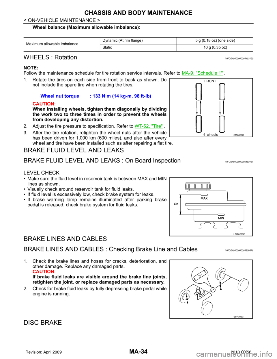
1. Rotate the tires on each side from front to back as shown. Do not include the spare tire when rotating the tires.
CAUTION:
When installing wheel s, tighten them diagonally by dividing
the work two to three times in order to prevent the wheels
from developing any distortion.
2. Adjust the tire pressure to specification. Refer to WT-52, "
Tire" .
3. After the tire rotation, retighten the wheel nuts after the vehicle has been driven for 1,000 km (600 miles), and also after every
wheel and tire have been installed such as after repairing a flat tire.
BRAKE FLUID LEVEL AND LEAKS
BRAKE FLUID LEVEL AND LEAK S : On Board InspectionINFOID:0000000005403161
LEVEL CHECK
• Make sure the fluid level in reservoir tank is between MAX and MIN
lines as shown.
• Visually check around reservoir tank for fluid leaks.
• If fluid level is excessively low, check brake system for leaks.
• If brake warning lamp remains illuminated after parking brake pedal is released, check brake system for fluid leaks.
BRAKE LINES AND CABLES
BRAKE LINES AND CABLES : Ch ecking Brake Line and CablesINFOID:0000000005259676
1. Check the brake lines and hoses for cracks, deterioration, and
other damage. Replace any damaged parts.
CAUTION:
If brake fluid leaks are visible around the brake line joints,
retighten the joint, or replace damaged parts as necessary.
2. Check for brake fluid leaks by fully depressing brake pedal while engine is running.
DISC BRAKE
Maximum allowable imbalance Dynamic (At rim flange) 5 g (0.18 oz) (one side)
Static
10 g (0.35 oz)
Wheel nut torque : 133 N·m (14 kg-m, 98 ft-lb)
SMA829C
LFIA0225E
SBR389C
Revision: April 20092010 QX56
Page 3179 of 4210
PRECAUTIONSRF-51
< PRECAUTION >
C
DE
F
G H
I
J
L
M A
B
RF
N
O P
5. When the repair work is completed, return the ignition switch to the ″LOCK ″ position before connecting
the battery cables. (At this time, the steering lock mechanism will engage.)
6. Perform a self-diagnosis check of al l control units using CONSULT-III.
PrecautionINFOID:0000000005147304
• Disconnect both battery cables in advance.
• Never tamper with or force air bag lid open, as this may adversely affect air bag performance.
• Be careful not to scratch pad and other parts.
• When removing or disassembling any part, be careful not to damage or deform it. Protect parts which may
get in the way with cloth.
• When removing parts with a screwdriver or other tool , protect parts by wrapping them with vinyl or tape.
• Keep removed parts protected with cloth.
• If a clip is deformed or damaged, replace it.
• If an unreusable part is removed, replace it with a new one.
• Tighten bolts and nuts firmly to the specified torque.
• After re-assembly has been completed, make sure each part functions correctly.
• Remove stains in the following way.
Water-soluble stains:
Dip a soft cloth in warm water, and then squeeze it tight ly. After wiping the stain, wipe with a soft dry cloth.
Oil stain:
Dissolve a synthetic detergent in warm water (density of 2 to 3% or less), dip the cloth, then clean off the stain
with the cloth. Next, dip the cloth in fresh water and squeeze it tightly. Then clean off the detergent completely.
Then wipe the area with a soft dry cloth.
• Do not use any organic solvent, such as thinner or benzine.
Revision: April 20092010 QX56
Page 3183 of 4210
SUNROOF SYSTEMRF-55
< ON-VEHICLE REPAIR >
C
DE
F
G H
I
J
L
M A
B
RF
N
O P
GAP ADJUSTMENT
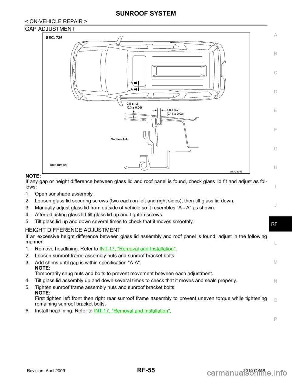
NOTE:
If any gap or height difference between glass lid and roof panel is found, check glass lid fit and adjust as fol-
lows:
1. Open sunshade assembly.
2. Loosen glass lid securing screws (two each on left and right sides), then tilt glass lid down.
3. Manually adjust glass lid from outside of v ehicle so it resembles "A - A" as shown.
4. After adjusting glass lid tilt glass lid up and tighten screws.
5. Tilt glass lid up and down several times to check that it moves smoothly.
HEIGHT DIFFERE NCE ADJUSTMENT
If an excessive height difference between glass lid assemb ly and roof panel is found, adjust in the following
manner:
1. Remove headlining. Refer to INT-17, "
Removal and Installation".
2. Loosen sunroof frame assembly nuts and sunroof bracket bolts.
3. Add shims until gap is within specification "A-A". NOTE:
Temporarily snug nuts and bolts to prevent movement between each adjustment.
4. Tilt glass lid assembly up and down several times to check that it moves and seals properly.
5. Tighten sunroof frame assembly nuts and sunroof bracket bolts. NOTE:
First tighten left front then right rear sunroof frame assembly to prevent uneven torque while tightening
remaining sunroof bracket bolts.
6. Install headlining. Refer to INT-17, "
Removal and Installation".
WIIA0304E
Revision: April 20092010 QX56