exl INFINITI QX56 2010 Factory Service Manual
[x] Cancel search | Manufacturer: INFINITI, Model Year: 2010, Model line: QX56, Model: INFINITI QX56 2010Pages: 4210, PDF Size: 81.91 MB
Page 2128 of 4210

EXL-152
< REMOVAL AND INSTALLATION >
FRONT FOG LAMP
FRONT FOG LAMP
Bulb ReplacementINFOID:0000000005146702
FRONT FOG LAMP
Removal
1. Remove the front turn/fog lamp assembly. Refer to EXL-152, "Removal and Installation".
2. Turn the bulb cover counterclockwise to remove it.
3. Unlatch retaining spring.
4. Remove bulb and disconnect the connector. CAUTION:
• Do not touch the glass of bulb directly by hand. Keep
grease and other oily substances away from it. Do not
touch bulb by hand while it is lit or right after being turned
off. Burning may result.
• Do not leave bulb out of fog la mp reflector for a long time
because dust, moisture smoke, etc. may affect the perfor-
mance of fog lamp. When replacing bulb, be sure to
replace it with new one.
Installation
Installation is in the reverse order of removal.
Removal and InstallationINFOID:0000000005146703
FRONT FOG LAMP
The fog lamp is a semi-sealed beam type which uses a replaceable halogen bulb.
CAUTION:
• Do not leave fog lamp assembly without bulb for a long period of time. Dust, moisture, smoke, etc. entering the fog lamp body may affect the perf ormance. Remove the bulb from the headlamp assem-
bly just before replacement bulb is installed.
• Grasp only the plastic base when handling the bulb. Never touch the glass envelope. Touching the
glass could significantly affect the bulb life and/or fog lamp performance.
Removal
1. Remove the front turn/fog lamp finisher.
2. Remove bolt and pull fog lamp out of front fascia.
3. Disconnect electrical connector.
WKIA1886E
WKIA1887E
WKIA1888E
Revision: April 20092010 QX56
Page 2129 of 4210
FRONT FOG LAMPEXL-153
< REMOVAL AND INSTALLATION >
C
DE
F
G H
I
J
K
M A
B
EXL
N
O P
Installation
Installation is in the reverse order of removal.
Revision: April 20092010 QX56
Page 2130 of 4210
EXL-154
< REMOVAL AND INSTALLATION >
LIGHTING & TURN SIGNAL SWITCH
LIGHTING & TURN SIGNAL SWITCH
Removal and InstallationINFOID:0000000005146704
REMOVAL
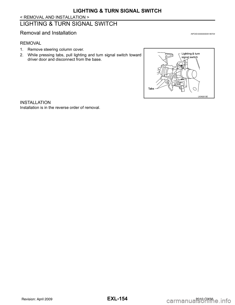
1. Remove steering column cover.
2. While pressing tabs, pull lighting and turn signal switch toward
driver door and disconnect from the base.
INSTALLATION
Installation is in the reverse order of removal.
LKIA0013E
Revision: April 20092010 QX56
Page 2131 of 4210
HAZARD SWITCHEXL-155
< REMOVAL AND INSTALLATION >
C
DE
F
G H
I
J
K
M A
B
EXL
N
O P
HAZARD SWITCH
Removal and InstallationINFOID:0000000005146705
REMOVAL
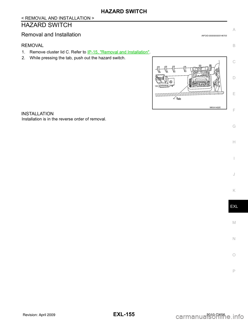
1. Remove cluster lid C. Refer to IP-15, "Removal and Installation".
2. While pressing the tab, push out the hazard switch.
INSTALLATION
Installation is in the reverse order of removal.
WKIA1402E
Revision: April 20092010 QX56
Page 2132 of 4210
EXL-156
< REMOVAL AND INSTALLATION >
LICENSE PLATE LAMP
LICENSE PLATE LAMP
Bulb ReplacementINFOID:0000000005146706
LICENSE PLATE LAMP
Removal
1. Remove back door lower finisher. Refer to EXT-24, "Removal and Installation".
2. Turn bulb socket counterclockwise to remove it.
3. Pull bulb from socket.
Installation
Installation is in the reverse order of removal.
Removal and InstallationINFOID:0000000005146707
LICENSE PLATE LAMP
Removal
1. Remove back door lower finisher. Refer to INT-21, "Removal and Installation".
2. Remove license plate lamp screws.
3. Remove license plate lamp.
Installation
Installation is in the reverse order of removal.
Revision: April 20092010 QX56
Page 2133 of 4210

STOP LAMPEXL-157
< REMOVAL AND INSTALLATION >
C
DE
F
G H
I
J
K
M A
B
EXL
N
O P
STOP LAMP
Bulb ReplacementINFOID:0000000005146708
HIGH-MOUNTED STOP LAMP
NOTE:
High-mounted stop lamp bulbs are not serviceable.
STOP LAMP
Refer to EXL-157, "Removal and Installation".
Removal and InstallationINFOID:0000000005146709
HIGH-MOUNTED STOP LAMP
Removal
1. Remove back door upper finisher. Refer to INT-21, "Removal and Installation".
2. Remove 2 nuts and remove high-mounted stop lamp.
Installation
Installation is in the reverse order of removal.
STOP LAMP
Refer to EXL-158, "Removal and Installation".
WKIA1397E
Revision: April 20092010 QX56
Page 2134 of 4210
EXL-158
< REMOVAL AND INSTALLATION >
REAR COMBINATION LAMP
REAR COMBINATION LAMP
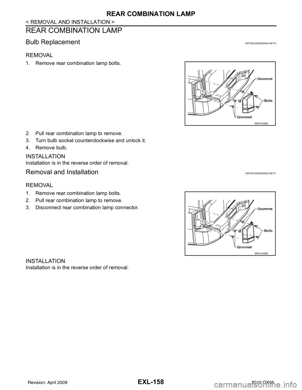
Bulb ReplacementINFOID:0000000005146710
REMOVAL
1. Remove rear combination lamp bolts.
2. Pull rear combination lamp to remove.
3. Turn bulb socket counterclockwise and unlock it.
4. Remove bulb.
INSTALLATION
Installation is in the reverse order of removal.
Removal and InstallationINFOID:0000000005146711
REMOVAL
1. Remove rear combination lamp bolts.
2. Pull rear combination lamp to remove.
3. Disconnect rear combination lamp connector.
INSTALLATION
Installation is in the reverse order of removal.
WKIA1393E
WKIA1393E
Revision: April 20092010 QX56
Page 2135 of 4210

BULB SPECIFICATIONSEXL-159
< SERVICE DATA AND SPECIFICATIONS (SDS)
C
DE
F
G H
I
J
K
M A
B
EXL
N
O P
SERVICE DATA AND SPECIFICATIONS (SDS)
BULB SPECIFICATIONS
HeadlampINFOID:0000000005146712
*: Always check with the Parts Department for the latest parts information.
Exterior LampINFOID:0000000005146713
*: Always check with the Parts Department for the latest parts information. Item
Wattage (W)*
Low 35
High 60/65
ItemWattage (W)*
Front combination lamp Parking lamp (inner)
7
Parking lamp (outer) 7
Side marker lamp (front) 7
Rear combination lamp Stop/Tail lamp
LED*
Side marker lamp (rear) *
Turn signal lamp 27
Back-up lamp *
Turn/fog lamp Fog
55
Turn 21
Puddle lamp 8
License plate lamp *
High-mounted stop lamp LED*
Revision: April 20092010 QX56
Page 2151 of 4210

EXT-16
< SERVICE INFORMATION >
REAR BUMPER
REMOVAL
1. Remove the rear combination lamps LH and RH. Refer to EXL-158, "Removal and Installation".
2. Remove the rear fascia assembly screws under the rear combination lamps LH and RH.
3. Remove the quarter panel trim covers LH and RH.
4. Disconnect the sonar sensor harness c onnector under the rear fascia assembly.
5. Release the retainer clips on both sides of the rear fascia assembly with a 1/4 turn and top S clips and remove the fascia assembly.
6. Detach the I-key antenna from the energy absorber.
7. Remove the energy absorber.
8. Remove the reinforcement assembly.
9. Remove the nuts and remove the retainer assembly. • Remove the S clips from the retainer assembly.
10. Disconnect the sonar sensors from the sonar sensor retainers.
11. Remove the sonar sensors and harness from the rear fascia assembly. • Disconnect the sonar sensors from the harness.
• Remove the sonar sensor retainers from the rear fascia assembly.
12. Remove the bolts on each side of the tow hitch and remove the tow hitch.
13. Remove the drafter duct from under the LH quarter pane, if necessary.
INSTALLATION
Installation is in the reverse order of removal.
10. Rear fascia assembly 11. Sonar sensor retainer12. Reinforcement assembly
13. Tow hitch 14. Quarter panel trim cover RH
Revision: April 20092010 QX56
Page 2155 of 4210

EXT-20
< SERVICE INFORMATION >
FRONT FENDER
FRONT FENDER
Removal and InstallationINFOID:0000000005147322
REMOVAL
1. Remove the headlamp assembly. Refer to EXL-149, "Removal and Installation".
2. Remove the over fender. Refer to EXT-21
.
3. Remove the fender protector. Refer to EXT-23
.
4. Remove the hood stay. Refer to DLK-234, "
Removal and Installation of Hood Assembly".
5. Remove the front fender.
INSTALLATION
Installation is in the reverse order of removal.
1. Front fender 2. Over fender3. Headlamp assembly
4. Fender protector
WIIA0956E
Revision: April 20092010 QX56