weight INFINITI QX56 2010 Factory User Guide
[x] Cancel search | Manufacturer: INFINITI, Model Year: 2010, Model line: QX56, Model: INFINITI QX56 2010Pages: 4210, PDF Size: 81.91 MB
Page 1619 of 4210
![INFINITI QX56 2010 Factory User Guide EC-266
< COMPONENT DIAGNOSIS >[VK56DE]
P0456 EVAP CONTROL SYSTEM
2. Does water drain from the EVAP canister?
Ye s o r N o
Yes >> GO TO 10.
No (With CONSULT-III)>>GO TO 12.
No (Without CONSULT-III)>> INFINITI QX56 2010 Factory User Guide EC-266
< COMPONENT DIAGNOSIS >[VK56DE]
P0456 EVAP CONTROL SYSTEM
2. Does water drain from the EVAP canister?
Ye s o r N o
Yes >> GO TO 10.
No (With CONSULT-III)>>GO TO 12.
No (Without CONSULT-III)>>](/img/42/57032/w960_57032-1618.png)
EC-266
< COMPONENT DIAGNOSIS >[VK56DE]
P0456 EVAP CONTROL SYSTEM
2. Does water drain from the EVAP canister?
Ye s o r N o
Yes >> GO TO 10.
No (With CONSULT-III)>>GO TO 12.
No (Without CONSULT-III)>>GO TO 13.
10.CHECK EVAP CANISTER
Weigh the EVAP canister with the EVAP canister vent control valve and EVAP control system pressure sensor
attached.
The weight should be less than 3.2 kg (7.1 lb).
OK or NG
OK (With CONSULT-III)>>GO TO 12.
OK (Without CONSULT-III)>>GO TO 13.
NG >> GO TO 11.
11 .DETECT MALFUNCTIONING PART
Check the following.
• EVAP canister for damage
• EVAP hose between EVAP canister and vehicle frame for clogging or poor connection
>> Repair hose or replace EVAP canister.
12.CHECK EVAP CANISTER PURGE VOLUME CONTROL SOLENOID VALVE OPERATION
With CONSULT-III
1. Disconnect vacuum hose to EVAP canister purge volume control solenoid valve at EVAP service port.
2. Start engine.
3. Perform “PURG VOL CONT/V ” in “ACTIVE TEST” mode.
4. Touch “Qu” on CONSULT-III screen to increase “PURG VOL CONT/V” opening to 100%.
5. Check vacuum hose for vacuum when revving engine up to 2,000 rpm.
OK or NG
OK >> GO TO 15.
NG >> GO TO 14.
13.CHECK EVAP CANISTER PURGE VOLUME CONTROL SOLENOID VALVE OPERATION
Without CONSULT-III
1. Start engine and warm it up to normal operating temperature.
2. Stop engine.
3. Disconnect vacuum hose to EVAP canister purge volume control solenoid valve at EVAP service port.
4. Start engine and let it idle for at least 80 seconds.
5. Check vacuum hose for vacuum when revving engine up to 2,000 rpm.
OK or NG
OK >> GO TO 16.
NG >> GO TO 14.
14.CHECK VACUUM HOSE
Check vacuum hoses for clogging or disconnection. Refer to EC-37, "
Description".
OK or NG
BBIA0351E
Vacuum should exist.
Vacuum should exist.
Revision: April 20092010 QX56
Page 1765 of 4210
![INFINITI QX56 2010 Factory User Guide EC-412
< COMPONENT DIAGNOSIS >[VK56DE]
ON BOARD REFUELING VAPOR RECOVERY (ORVR)
ON BOARD REFUELING VAPOR RECOVERY (ORVR)
System DescriptionINFOID:0000000005149485
From the beginning of refueling, the INFINITI QX56 2010 Factory User Guide EC-412
< COMPONENT DIAGNOSIS >[VK56DE]
ON BOARD REFUELING VAPOR RECOVERY (ORVR)
ON BOARD REFUELING VAPOR RECOVERY (ORVR)
System DescriptionINFOID:0000000005149485
From the beginning of refueling, the](/img/42/57032/w960_57032-1764.png)
EC-412
< COMPONENT DIAGNOSIS >[VK56DE]
ON BOARD REFUELING VAPOR RECOVERY (ORVR)
ON BOARD REFUELING VAPOR RECOVERY (ORVR)
System DescriptionINFOID:0000000005149485
From the beginning of refueling, the air and vapor insi
de the fuel tank go through refueling EVAP vapor cut
valve and EVAP/ORVR line to the EVAP canister. The vapor is absorbed by the EVAP canister and the air is
released to the atmosphere.
When the refueling has reached the full level of the fuel tank, the refueling EVAP vapor cut valve is closed and
refueling is stopped because of auto shut-off. The vapor which was absorbed by the EVAP canister is purged
during driving.
WARNING:
When conducting inspections below, be sure to observe the following:
• Put a “CAUTION: FLAMMABLE” sign in workshop.
• Do not smoke while servicing fuel system. Keep open flames and sparks away from work area.
• Be sure to furnish the workshop with a CO
2 fire extinguisher.
CAUTION:
• Before removing fuel line parts, carry out the following procedures:
- Put drained fuel in an explosion-pr oof container and put lid on securely.
- Release fuel pressure from fuel line. Refer to EC-489, "
Fuel Pressure Check".
- Disconnect battery ground cable.
• Always replace O-ring when the fu el gauge retainer is removed.
• Do not kink or twist hose and tube when they are installed.
• Do not tighten hose and clamps excessively to avoid damaging hoses.
• After installation, run engine and check for fuel leaks at connection.
• Do not attempt to top off the fuel tank afte r the fuel pump nozzle shuts off automatically.
Continued refueling may cause fuel overflow, r esulting in fuel spray and possibly a fire.
Diagnosis ProcedureINFOID:0000000005149486
SYMPTOM: FUEL ODOR FROM EVAP CANISTER IS STRONG.
1.CHECK EVAP CANISTER
1. Remove EVAP canister with EVAP canister vent control valve and EVAP control system pressure sensor attached.
2. Weigh the EVAP canister with EVAP canister vent control valve and EVAP control system pressure sensor
attached.
The weight should be l ess than 3.2 kg (7.1 lb).
OK or NG
OK >> GO TO 2.
NG >> GO TO 3.
2.CHECK IF EVAP CANISTER SATURATED WITH WATER
PBIB1068E
Revision: April 20092010 QX56
Page 1766 of 4210
![INFINITI QX56 2010 Factory User Guide ON BOARD REFUELING VAPOR RECOVERY (ORVR)EC-413
< COMPONENT DIAGNOSIS > [VK56DE]
C
D
E
F
G H
I
J
K L
M A
EC
NP
O
Does water drain from
the EVAP canister?
Ye s o r N o
Yes >> GO TO 3.
No >> GO TO 5.
INFINITI QX56 2010 Factory User Guide ON BOARD REFUELING VAPOR RECOVERY (ORVR)EC-413
< COMPONENT DIAGNOSIS > [VK56DE]
C
D
E
F
G H
I
J
K L
M A
EC
NP
O
Does water drain from
the EVAP canister?
Ye s o r N o
Yes >> GO TO 3.
No >> GO TO 5.](/img/42/57032/w960_57032-1765.png)
ON BOARD REFUELING VAPOR RECOVERY (ORVR)EC-413
< COMPONENT DIAGNOSIS > [VK56DE]
C
D
E
F
G H
I
J
K L
M A
EC
NP
O
Does water drain from
the EVAP canister?
Ye s o r N o
Yes >> GO TO 3.
No >> GO TO 5.
3.REPLACE EVAP CANISTER
Replace EVAP canister with a new one.
>> GO TO 4.
4.DETECT MALFUNCTIONING PART
Check the EVAP hose between EVAP canister and vehicle frame for clogging or poor connection.
>> Repair or replace EVAP hose.
5.CHECK REFUELING EVAP VAPOR CUT VALVE
Refer to EC-414, "
Component Inspection".
OK or NG
OK >> INSPECTION END
NG >> Replace refueling EVAP vapor cut valve with fuel tank.
SYMPTOM: CANNOT REFUEL/FUEL ODOR FROM THE FUEL FILLER OPENING IS STRONG
WHILE REFUELING.
1.CHECK EVAP CANISTER
1. Remove EVAP canister with EVAP canister vent c ontrol valve and EVAP control system pressure sensor
attached.
2. Weigh the EVAP canister with EVAP canister vent control valve and EVAP control system pressure sensor
attached.
The weight should be l ess than 3.2 kg (7.1 lb).
OK or NG
OK >> GO TO 2.
NG >> GO TO 3.
2.CHECK IF EVAP CANISTER SATURATED WITH WATER
Does water drain from the EVAP canister?
Ye s o r N o
Yes >> GO TO 3.
No >> GO TO 5.
3.REPLACE EVAP CANISTER
Replace EVAP canister with a new one.
>> GO TO 4.
BBIA0351E
BBIA0351E
Revision: April 20092010 QX56
Page 1828 of 4210
![INFINITI QX56 2010 Factory User Guide ECM
EC-475
< ECU DIAGNOSIS > [VK56DE]
C
D
E
F
G H
I
J
K L
M A
EC
NP
O
HOW TO ERASE EMISSION-RELATED DIAGNOSTIC INFORMATION
How to Erase DTC
WITH CONSULT-III
The emission related diagnostic informatio INFINITI QX56 2010 Factory User Guide ECM
EC-475
< ECU DIAGNOSIS > [VK56DE]
C
D
E
F
G H
I
J
K L
M A
EC
NP
O
HOW TO ERASE EMISSION-RELATED DIAGNOSTIC INFORMATION
How to Erase DTC
WITH CONSULT-III
The emission related diagnostic informatio](/img/42/57032/w960_57032-1827.png)
ECM
EC-475
< ECU DIAGNOSIS > [VK56DE]
C
D
E
F
G H
I
J
K L
M A
EC
NP
O
HOW TO ERASE EMISSION-RELATED DIAGNOSTIC INFORMATION
How to Erase DTC
WITH CONSULT-III
The emission related diagnostic information in the ECM can be erased by selecting “All Erase” in the “Descrip-
tion” of “FINAL CHECK” mode with CONSULT-III.
WITH GST
The emission related diagnostic information in the ECM can be erased by selecting Service $04 with GST.
NOTE:
If the DTC is not for A/T related items (see EC-459, "
DTC Index"), skip step 2.
MISFIREA2H No.1 Cylinder Misfire
P0301 0BH 24H
EWMA (Exponential Weighted Moving
Average) misfire counts for last 10 driv-
ing cycles
P0301 0CH 24H Misfire counts for last/current driving cy-
cles
A3H No.2 Cylinder Misfire P0302 0BH 24H
EWMA (Exponential Weighted Moving
Average) misfire counts for last 10 driv-
ing cycles
P0302 0CH 24H Misfire counts for last/current driving cy-
cles
A4H No.3 Cylinder Misfire P0303 0BH 24H
EWMA (Exponential Weighted Moving
Average) misfire counts for last 10 driv-
ing cycles
P0303 0CH 24H Misfire counts for last/current driving cy-
cles
A5H No.4 Cylinder Misfire P0304 0BH 24H
EWMA (Exponential Weighted Moving
Average) misfire counts for last 10 driv-
ing cycles
P0304 0CH 24H Misfire counts for last/current driving cy-
cles
A6H No.5 Cylinder Misfire P0305 0BH 24H
EWMA (Exponential Weighted Moving
Average) misfire counts for last 10 driv-
ing cycles
P0305 0CH 24H Misfire counts for last/current driving cy-
cles
A7H No.6 Cylinder Misfire P0306 0BH 24H
EWMA (Exponential Weighted Moving
Average) misfire counts for last 10 driv-
ing cycles
P0306 0CH 24H Misfire counts for last/current driving cy-
cles
A8H No.7 Cylinder Misfire P0307 0BH 24H
EWMA (Exponential Weighted Moving
Average) misfire counts for last 10 driv-
ing cycles
P0307 0CH 24H Misfire counts for last/current driving cy-
cles
A9H No.8 Cylinder Misfire P0308 0BH 24H
EWMA (Exponential Weighted Moving
Average) misfire counts for last 10 driv-
ing cycles
P0308 0CH 24H Misfire counts for last/current driving cy-
cles
Item
OBD-
MID Self-diagnostic test item
DTCTest value and Test
limit
(GST display) Description
TID Unit and
Scaling ID
Revision: April 20092010 QX56
Page 1832 of 4210
![INFINITI QX56 2010 Factory User Guide ENGINE CONTROL SYSTEM SYMPTOMSEC-479
< SYMPTOM DIAGNOSIS > [VK56DE]
C
D
E
F
G H
I
J
K L
M A
EC
NP
O
SYMPTOM
Reference
page
HARD/NO START/RESTART (EXCP. HA)
ENGINE STALL
HESITATION/SURGING/FLAT SPOT
S INFINITI QX56 2010 Factory User Guide ENGINE CONTROL SYSTEM SYMPTOMSEC-479
< SYMPTOM DIAGNOSIS > [VK56DE]
C
D
E
F
G H
I
J
K L
M A
EC
NP
O
SYMPTOM
Reference
page
HARD/NO START/RESTART (EXCP. HA)
ENGINE STALL
HESITATION/SURGING/FLAT SPOT
S](/img/42/57032/w960_57032-1831.png)
ENGINE CONTROL SYSTEM SYMPTOMSEC-479
< SYMPTOM DIAGNOSIS > [VK56DE]
C
D
E
F
G H
I
J
K L
M A
EC
NP
O
SYMPTOM
Reference
page
HARD/NO START/RESTART (EXCP. HA)
ENGINE STALL
HESITATION/SURGING/FLAT SPOT
SPARK KNOCK/DETONATION
LACK OF POWER/POOR ACCELERATION
HIGH IDLE/LOW IDLE
ROUGH IDLE/HUNTING
IDLING VIBRATION
SLOW/NO RETURN TO IDLE
OVERHEATS/WATER TEMPERATURE HIGH
EXCESSIVE FUEL CONSUMPTION
EXCESSIVE OIL CONSUMPTION
BATTERY DEAD (UNDER CHARGE)
Warranty symptom code AA AB AC AD AE AF AG AH AJ AK AL AM HA
Fuel Fuel tank 5
5 FL-11
Fuel piping
5 5 5 5 55FL-6
Va p o r l o c k —
Valve deposit 5 555 55 5—
Poor fuel (Heavy weight gasoline,
Low octane) —
Air Air duct
55555 5 EM-25
Air cleaner
EM-25
Air leakage from air duct
(Mass air flow sensor — electric
throttle control actuator)
5555 EM-25
Electric throttle control actuator
EM-26
Air leakage from intake manifold/
Collector/GasketEM-26
Cranking Battery
111111
11
PG-74
Generator circuit
CHG-6
Starter circuit3 STR-8
Signal plate6 EM-45
Park/Neutral position (PNP) sig-
nal4
TM-45
Engine Cylinder head
55555 55 5 EM-68
Cylinder head gasket 4 3
Cylinder block
66666 66 64
EM-83
Piston
Piston ring
Connecting rod
Bearing
Crankshaft
Va l v e
mecha-
nism Timing chain
55555 55 5EM-45
Camshaft
EM-53
Intake valve timing controlEM-53
Intake valve
3EM-68
Exhaust valve
Revision: April 20092010 QX56
Page 1931 of 4210

EM-80
< REMOVAL AND INSTALLATION >
ENGINE ASSEMBLY
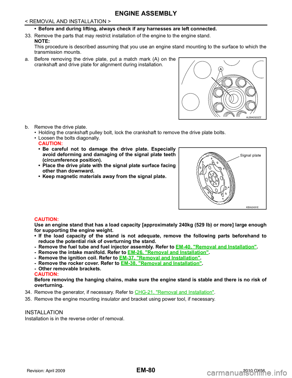
• Before and during lifting, always check if any harnesses are left connected.
33. Remove the parts that may restrict installation of the engine to the engine stand. NOTE:
This procedure is described assuming that you use an engine stand mounting to the surface to which the
transmission mounts.
a. Before removing the drive plate, put a match mark (A) on the crankshaft and drive plate for alignment during installation.
b. Remove the drive plate. • Holding the crankshaft pulley bolt, lock the crankshaft to remove the drive plate bolts.
• Loosen the bolts diagonally.CAUTION:
• Be careful not to damage the drive plate. Especiallyavoid deforming and damaging of the signal plate teeth
(circumference position).
• Place the drive plate with th e signal plate surface facing
other than downward.
• Keep magnetic materials away from the signal plate.
CAUTION:
Use an engine stand that has a load capacity [a pproximately 240kg (529 lb) or more] large enough
for supporting the engine weight.
• If the load capacity of the stand is not adeq uate, remove the following parts beforehand to
reduce the potential risk of overturning the stand.
- Remove the fuel tube and fuel injector assembly. Refer to EM-40, "
Removal and Installation".
- Remove the intake manifold. Refer to EM-26, "
Removal and Installation".
- Remove the ignition coil. Refer to EM-37, "
Removal and Installation".
- Remove the rocker cover. Refer to EM-38, "
Removal and Installation".
- Other removable brackets.
CAUTION:
Before removing the hanging chains, make sure th e engine stand is stable and there is no risk of
overturning.
34. Remove the generator, if necessary. Refer to CHG-21, "
Removal and Installation".
35. Remove the engine mounting insulator and bracket using power tool, if necessary.
INSTALLATION
Installation is in the reverse order of removal.
ALBIA0522ZZ
KBIA2491E
Revision: April 20092010 QX56
Page 2121 of 4210

ADJUSTMENT AND INSPECTIONEXL-145
< ON-VEHICLE REPAIR >
C
DE
F
G H
I
J
K
M A
B
EXL
N
O P
ON-VEHICLE REPAIR
ADJUSTMENT AND INSPECTION
HEADLAMP
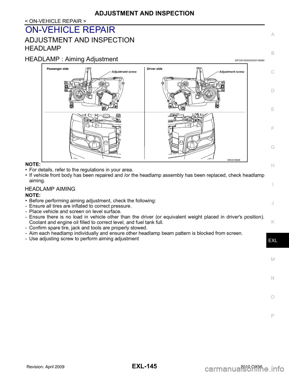
HEADLAMP : Aiming AdjustmentINFOID:0000000005146696
NOTE:
• For details, refer to the regulations in your area.
• If vehicle front body has been repaired and /or the headlamp assembly has been replaced, check headlamp
aiming.
HEADLAMP AIMING
NOTE:
• Before performing aiming adjustment, check the following:
- Ensure all tires are inflated to correct pressure.
- Place vehicle and screen on level surface.
- Ensure there is no load in vehicle other than the driver (or equivalent weight placed in driver's position). Coolant and engine oil filled to correct level, and fuel tank full.
- Confirm spare tire, jack and tools are properly stowed.
- Aim each headlamp individually and ensure other headlamp beam pattern is blocked from screen.
- Use adjusting screw to perform aiming adjustment
WKIA1859E
Revision: April 20092010 QX56
Page 2123 of 4210

ADJUSTMENT AND INSPECTIONEXL-147
< ON-VEHICLE REPAIR >
C
DE
F
G H
I
J
K
M A
B
EXL
N
O P
• See that vehicle is unloaded (except for full levels of coolant, engine oil and fuel, and spare tire, jack, and tools). Have the driver
or equivalent weight placed in driver seat.
Adjust aiming in the vertical direction by turning the adjustment
screw.
NOTE:
Access adjustment screw from underneath front bumper. Turn screw
clockwise to raise pattern and c ounterclockwise to lower pattern.
1. Set the distance between the screen and the center of the fog lamp lens as shown.
2. Turn front fog lamps ON.
3. Adjust front fog lamps using adjusting screw so that the top edge of the high intensity zone is 200 mm (7.9 in) below the height of
the fog lamp centers as shown.
• When performing adjustment, if necessary, cover the head-lamps and opposite fog lamp.
SEL350X
MEL327G
MEL328GA
Revision: April 20092010 QX56
Page 2244 of 4210

IDENTIFICATION INFORMATIONGI-21
< FEATURES OF NEW MODEL >
C
DE
F
G H
I
J
K L
M B
GI
N
O P
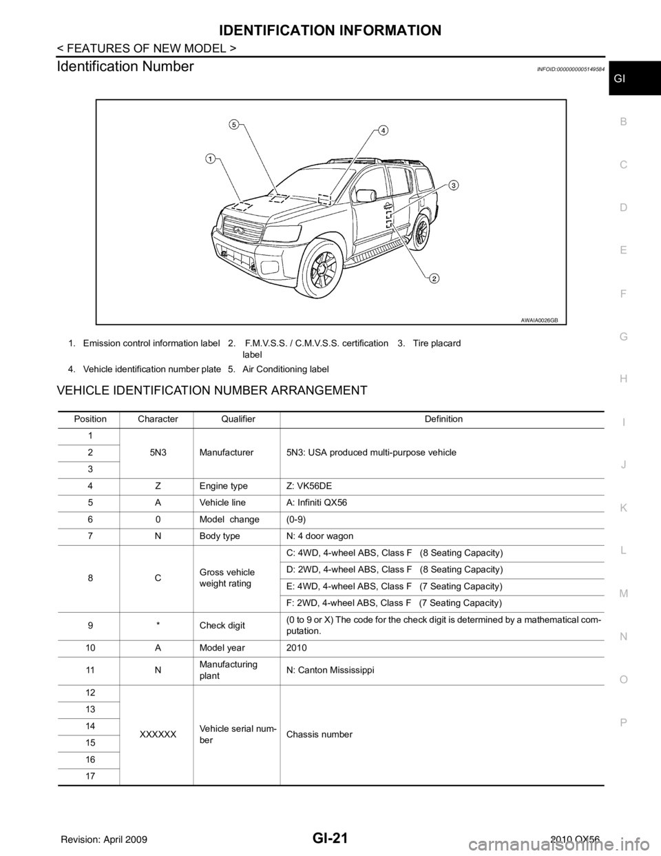
Identification NumberINFOID:0000000005149584
VEHICLE IDENTIFICATION NUMBER ARRANGEMENT
1. Emission control information label 2. F.M.V.S.S. / C.M.V.S.S. certification label3. Tire placard
4. Vehicle identification number plate 5. Air Conditioning label
AWAIA0026GB
Position Character Qualifier Definition
1 5N3 Manufacturer 5N3: USA produced multi-purpose vehicle
2
3
4 Z Engine type Z: VK56DE
5 A Vehicle line A: Infiniti QX56
6 0 Model change (0-9)
7 N Body type N: 4 door wagon
8C Gross vehicle
weight ratingC: 4WD, 4-wheel ABS, Class F (8 Seating Capacity)
D: 2WD, 4-wheel ABS, Class F (8 Seating Capacity)
E: 4WD, 4-wheel ABS, Class F (7 Seating Capacity)
F: 2WD, 4-wheel ABS, Class F (7 Seating Capacity)
9 * Check digit (0 to 9 or X) The code for the check digit is determined by a mathematical com-
putation.
10 A Model year 2010
11 NManufacturing
plant
N: Canton Mississippi
12
XXXXXX Vehicle serial num-
ber Chassis number
13
14
15
16
17
Revision: April 20092010 QX56
Page 2248 of 4210

PRECAUTIONSGI-25
< PRECAUTION >
C
DE
F
G H
I
J
K L
M B
GI
N
O P
2. Use the Intelligent Key or mechanical key to turn the ignition switch to the ″ACC ″ position. At this time, the
steering lock will be released.
3. Disconnect both battery cables. The steering lock will remain released and the steering wheel can be
rotated.
4. Perform the necessary repair operation.
5. When the repair work is completed, return the ignition switch to the ″LOCK ″ position before connecting
the battery cables. (At this time, the steering lock mechanism will engage.)
6. Perform a self-diagnosis check of al l control units using CONSULT-III.
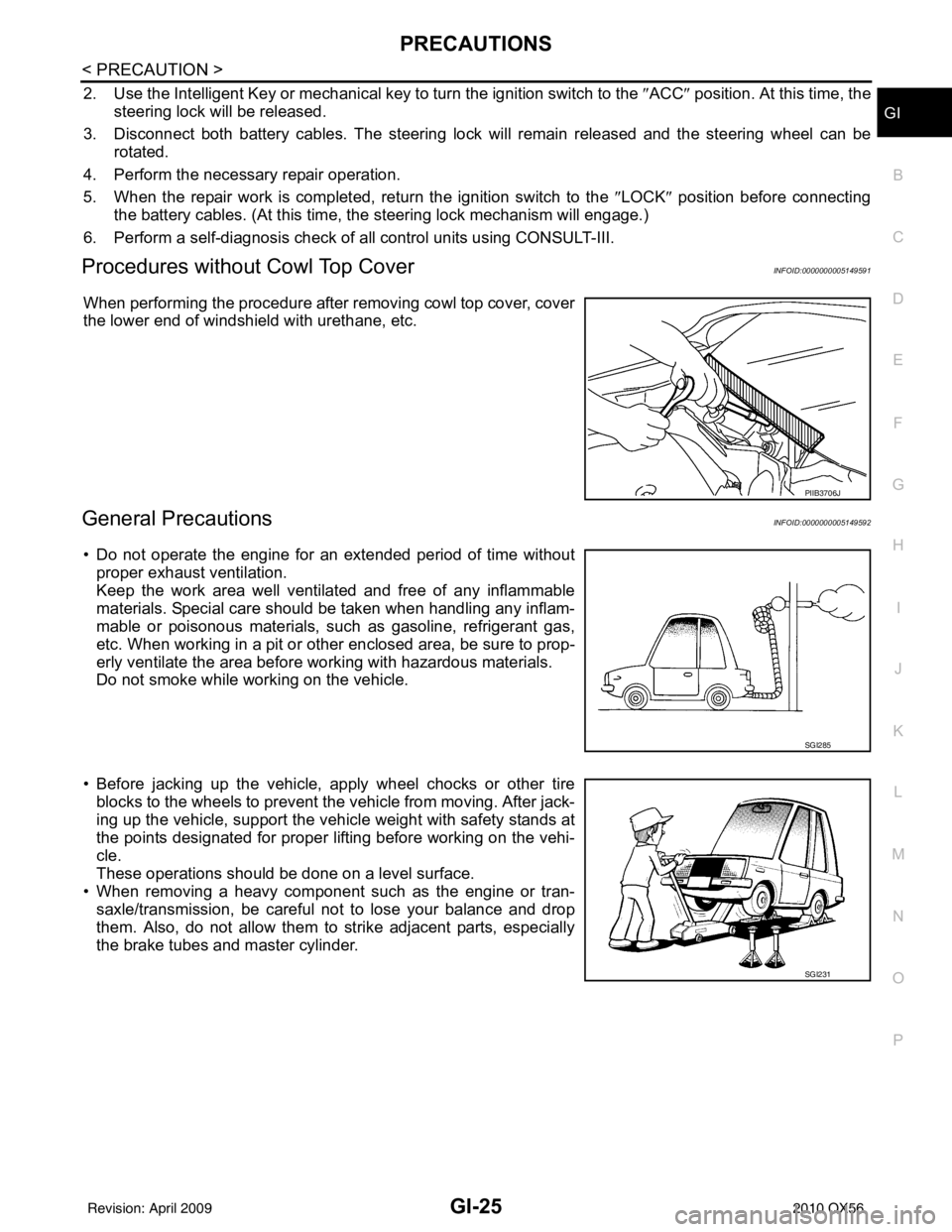
Procedures without Cowl Top CoverINFOID:0000000005149591
When performing the procedure after removing cowl top cover, cover
the lower end of windshield with urethane, etc.
General PrecautionsINFOID:0000000005149592
• Do not operate the engine for an extended period of time without
proper exhaust ventilation.
Keep the work area well ventilated and free of any inflammable
materials. Special care should be taken when handling any inflam-
mable or poisonous materials, such as gasoline, refrigerant gas,
etc. When working in a pit or ot her enclosed area, be sure to prop-
erly ventilate the area before working with hazardous materials.
Do not smoke while working on the vehicle.
• Before jacking up the vehicle, apply wheel chocks or other tire blocks to the wheels to prevent t he vehicle from moving. After jack-
ing up the vehicle, support the vehicle weight with safety stands at
the points designated for proper lifting before working on the vehi-
cle.
These operations should be done on a level surface.
• When removing a heavy component such as the engine or tran-
saxle/transmission, be careful not to lose your balance and drop
them. Also, do not allow them to strike adjacent parts, especially
the brake tubes and master cylinder.
PIIB3706J
SGI285
SGI231
Revision: April 20092010 QX56