width INFINITI QX56 2010 Factory User Guide
[x] Cancel search | Manufacturer: INFINITI, Model Year: 2010, Model line: QX56, Model: INFINITI QX56 2010Pages: 4210, PDF Size: 81.91 MB
Page 1427 of 4210
![INFINITI QX56 2010 Factory User Guide EC-74
< COMPONENT DIAGNOSIS >[VK56DE]
TROUBLE DIAGNOSIS - SPECIFICATION VALUE
COMPONENT DIAGNOSIS
TROUBLE DIAGNOSIS - SPECIFICATION VALUE
DescriptionINFOID:0000000005149081
The specification (SP) valu INFINITI QX56 2010 Factory User Guide EC-74
< COMPONENT DIAGNOSIS >[VK56DE]
TROUBLE DIAGNOSIS - SPECIFICATION VALUE
COMPONENT DIAGNOSIS
TROUBLE DIAGNOSIS - SPECIFICATION VALUE
DescriptionINFOID:0000000005149081
The specification (SP) valu](/img/42/57032/w960_57032-1426.png)
EC-74
< COMPONENT DIAGNOSIS >[VK56DE]
TROUBLE DIAGNOSIS - SPECIFICATION VALUE
COMPONENT DIAGNOSIS
TROUBLE DIAGNOSIS - SPECIFICATION VALUE
DescriptionINFOID:0000000005149081
The specification (SP) value indicates the tolerance of
the value that is displayed in “SPEC” of “DATA MONI-
TOR” mode with CONSULT-III during normal operation of the Engine Control System. When the value in
“SPEC” of “DATA MONITOR” mode is within the SP value, the Engine Control System is confirmed OK. When
the value in “SPEC” of “DATA MONITOR” mode is NOT within the SP value, the Engine Control System may
have one or more malfunctions.
The SP value is used to detect malfunctions that may af fect the Engine Control System, but will not light the
MIL.
The SP value will be displayed for the following three items:
• B/FUEL SCHDL (The fuel injection pulse width progr ammed into ECM prior to any learned on board correc-
tion)
• A/F ALPHA-B1/B2 (The mean value of air-fuel ratio feedback correction factor per cycle)
• MAS A/F SE-B1 (The signal voltage of the mass air flow sensor)
Testing ConditionINFOID:0000000005149082
• Vehicle driven distance: More than 5,000 km (3,107 miles)
• Barometric pressure: 98.3 - 104.3 kPa (1.003 - 1.064 kg/cm
2, 14.25 - 15.12 psi)
• Atmospheric temperature: 20 - 30 °C (68 - 86° F)
• Engine coolant temperature: 75 - 95 °C (167 - 203° F)
• Engine speed: Idle
• Transmission: Warmed-up
- After the engine is warmed up to normal operating temper ature, drive vehicle until “ATF TEMP SE 1” (A/T
fluid temperature sensor signal) indicates more than 60 °C (140° F).
• Electrical load: Not applied
- Rear window defogger switch, air conditioner switch, lighting switch are OFF. Steering wheel is straight
ahead.
Inspection ProcedureINFOID:0000000005149083
NOTE:
Perform “SPEC” in “DATA MONITOR” mode in maximum scale display.
1. Perform EC-13, "
Basic Inspection".
2. Confirm that the testing conditions indicated above are met.
3. Select “B/FUEL SCHDL”, “A/F ALPHA-B1”, “A/F ALPHA-B2” and “MAS A/F SE-B1” in “SPEC” of “DATA
MONITOR” mode with CONSULT-III.
4. Make sure that monitor items are within the SP value.
5. If NG, go to EC-75, "
Diagnosis Procedure".
Revision: April 20092010 QX56
Page 1454 of 4210
![INFINITI QX56 2010 Factory User Guide P0075, P0081 IVT CONTROL SOLENOID VALVEEC-101
< COMPONENT DIAGNOSIS > [VK56DE]
C
D
E
F
G H
I
J
K L
M A
EC
NP
O
P0075, P0081 IVT CONTROL SOLENOID VALVE
Component DescriptionINFOID:0000000005149105
Inta INFINITI QX56 2010 Factory User Guide P0075, P0081 IVT CONTROL SOLENOID VALVEEC-101
< COMPONENT DIAGNOSIS > [VK56DE]
C
D
E
F
G H
I
J
K L
M A
EC
NP
O
P0075, P0081 IVT CONTROL SOLENOID VALVE
Component DescriptionINFOID:0000000005149105
Inta](/img/42/57032/w960_57032-1453.png)
P0075, P0081 IVT CONTROL SOLENOID VALVEEC-101
< COMPONENT DIAGNOSIS > [VK56DE]
C
D
E
F
G H
I
J
K L
M A
EC
NP
O
P0075, P0081 IVT CONTROL SOLENOID VALVE
Component DescriptionINFOID:0000000005149105
Intake valve timing control solenoid valve is activated by ON/OFF
pulse duty (ratio) signals from the ECM.
The intake valve timing control solenoid valve changes the oil
amount and direction of flow through intake valve timing control unit
or stops oil flow.
The longer pulse width advances valve angle.
The shorter pulse width retards valve angle.
When ON and OFF pulse widths become equal, the solenoid valve
stops oil pressure flow to fix the intake valve angle at the control
position.
On Board Diagnosis LogicINFOID:0000000005149106
DTC Confirmation ProcedureINFOID:0000000005149107
1. If DTC Confirmation Procedure has been previously conducted, always perform the following procedure
before conducting the next step.
a. Turn ignition switch OFF and wait at least 10 seconds.
b. Turn ignition switch ON.
c. Turn ignition switch OFF and wait at least 10 seconds.
2. Start engine and let it idle for 5 seconds.
3. Check 1st trip DTC.
4. If 1st trip DTC is detected, go to EC-101, "
Diagnosis Procedure".
Diagnosis ProcedureINFOID:0000000005149108
1.CHECK INTAKE VALVE TIMING CONTROL SO LENOID VALVE POWER SUPPLY CIRCUIT
1. Turn ignition switch OFF.
2. Disconnect intake valve timing control solenoid valve harness connector.
PBIB1842E
DTC No. Trouble diagnosis name DTC detecting condition Possible cause
P0075
0075
(Bank 1) Intake valve timing control
solenoid valve circuit An improper voltage is sent to the ECM
through intake valve timing control solenoid
valve. • Harness or connectors
(Intake valve timing control solenoid valve
circuit is open or shorted.)
• Intake valve timing control solenoid valve
P0081
0081
(Bank 2)
BBIA0771E
Revision: April 20092010 QX56
Page 1879 of 4210

EM-28
< ON-VEHICLE REPAIR >
INTAKE MANIFOLD
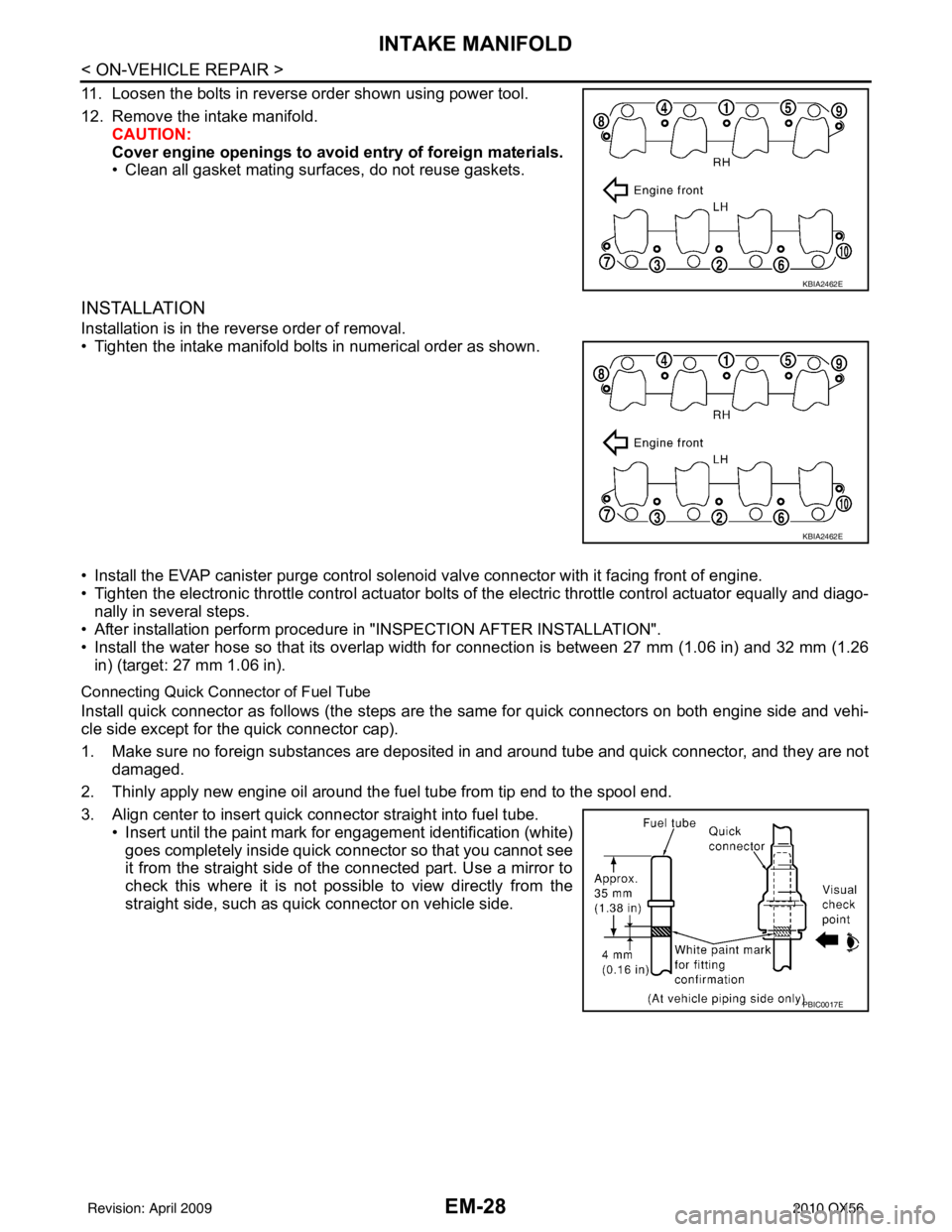
11. Loosen the bolts in reverse order shown using power tool.
12. Remove the intake manifold.CAUTION:
Cover engine openings to avoid entry of foreign materials.
• Clean all gasket mating surfaces, do not reuse gaskets.
INSTALLATION
Installation is in the reverse order of removal.
• Tighten the intake manifold bolts in numerical order as shown.
• Install the EVAP canister purge control sol enoid valve connector with it facing front of engine.
• Tighten the electronic throttle control actuator bolts of the electric throttle control actuator equally and diago-
nally in several steps.
• After installation perform procedure in "INSPECTION AFTER INSTALLATION".
• Install the water hose so that its overlap width for connection is between 27 mm (1.06 in) and 32 mm (1.26 in) (target: 27 mm 1.06 in).
Connecting Quick Connector of Fuel Tube
Install quick connector as follows (the steps are t he same for quick connectors on both engine side and vehi-
cle side except for the quick connector cap).
1. Make sure no foreign substances are deposited in and around tube and quick connector, and they are not
damaged.
2. Thinly apply new engine oil around the fuel tube from tip end to the spool end.
3. Align center to insert quick connector straight into fuel tube. • Insert until the paint mark for engagement identification (white)goes completely inside quick connector so that you cannot see
it from the straight side of the connected part. Use a mirror to
check this where it is not possible to view directly from the
straight side, such as quick connector on vehicle side.
KBIA2462E
KBIA2462E
PBIC0017E
Revision: April 20092010 QX56
Page 1949 of 4210

EM-98
< DISASSEMBLY AND ASSEMBLY >
ENGINE UNIT
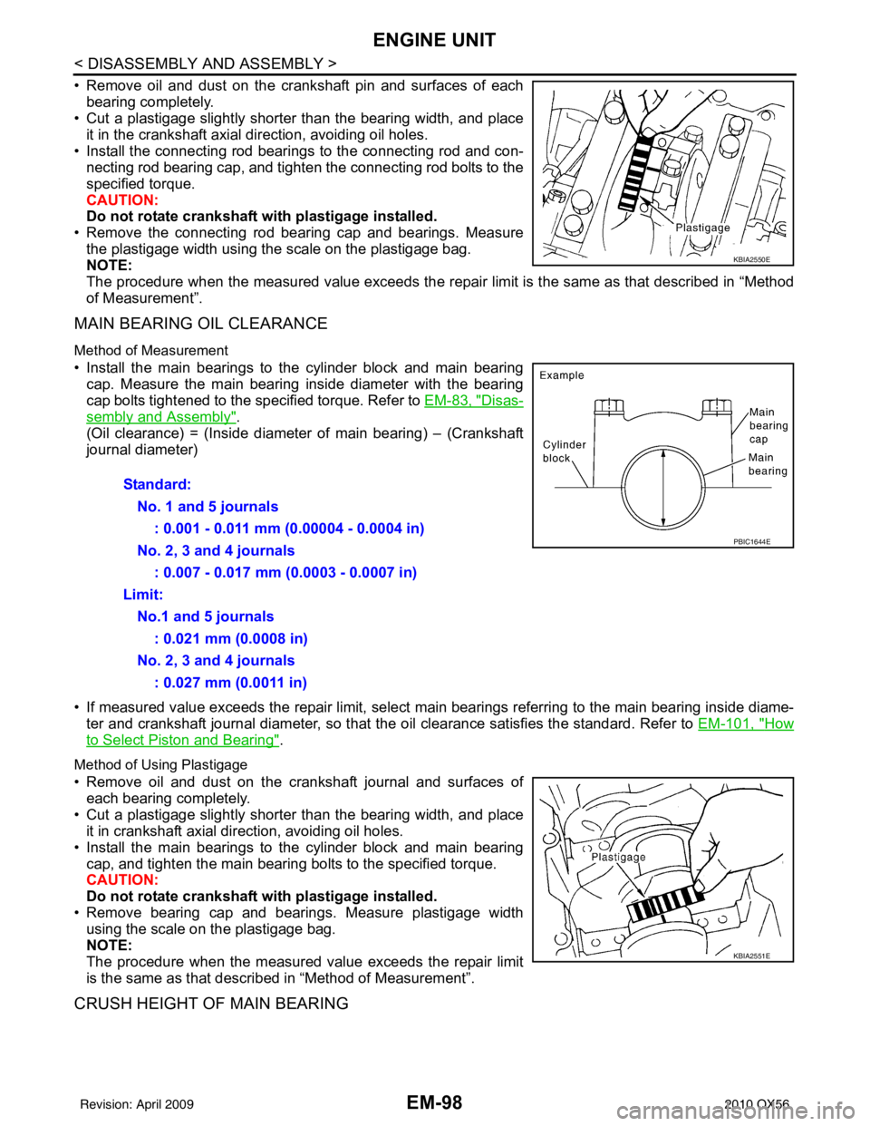
• Remove oil and dust on the crankshaft pin and surfaces of eachbearing completely.
• Cut a plastigage slightly shorter than the bearing width, and place
it in the crankshaft axial direction, avoiding oil holes.
• Install the connecting rod beari ngs to the connecting rod and con-
necting rod bearing cap, and tighten the connecting rod bolts to the
specified torque.
CAUTION:
Do not rotate crankshaft with plastigage installed.
• Remove the connecting rod bear ing cap and bearings. Measure
the plastigage width using the scale on the plastigage bag.
NOTE:
The procedure when the measured value exceeds the repair limit is the same as that described in “Method
of Measurement”.
MAIN BEARING OIL CLEARANCE
Method of Measurement
• Install the main bearings to the cylinder block and main bearing cap. Measure the main bearing inside diameter with the bearing
cap bolts tightened to the specified torque. Refer to EM-83, "
Disas-
sembly and Assembly".
(Oil clearance) = (Inside diameter of main bearing) – (Crankshaft
journal diameter)
• If measured value exceeds the repair limit, select main bearings referring to the main bearing inside diame-
ter and crankshaft journal diameter, so that the oil clearance satisfies the standard. Refer to EM-101, "
How
to Select Piston and Bearing".
Method of Using Plastigage
• Remove oil and dust on the crankshaft journal and surfaces of
each bearing completely.
• Cut a plastigage slightly shorter than the bearing width, and place it in crankshaft axial direction, avoiding oil holes.
• Install the main bearings to the cylinder block and main bearing cap, and tighten the main bearing bolts to the specified torque.
CAUTION:
Do not rotate crankshaft with plastigage installed.
• Remove bearing cap and bearings. Measure plastigage width using the scale on the plastigage bag.
NOTE:
The procedure when the measured value exceeds the repair limit
is the same as that descri bed in “Method of Measurement”.
CRUSH HEIGHT OF MAIN BEARING
KBIA2550E
Standard:
No. 1 and 5 journals : 0.001 - 0.011 mm (0.00004 - 0.0004 in)
No. 2, 3 and 4 journals : 0.007 - 0.017 mm (0.0003 - 0.0007 in)
Limit: No.1 and 5 journals : 0.021 mm (0.0008 in)
No. 2, 3 and 4 journals : 0.027 mm (0.0011 in)
PBIC1644E
KBIA2551E
Revision: April 20092010 QX56
Page 2246 of 4210

IDENTIFICATION INFORMATIONGI-23
< FEATURES OF NEW MODEL >
C
DE
F
G H
I
J
K L
M B
GI
N
O P
DimensionsINFOID:0000000005149586
Unit: mm (in)
Wheels & TiresINFOID:0000000005149587
* With Steel Wheel Drive type
2WD4WD
Overall length 5254 (206.9)5254 (206.9)
Overall width 2021 (79.6)2021 (79.6)
Overall height (with roof rack) 1948 (76.7)1968 (77.5)
Front tread width 1729 (68.1)1729 (68.1)
Rear tread width 1729 (68.1)1729 (68.1)
Wheelbase 3130 (123.2)3130 (123.2)
Minimum Running Ground Clearance (at front suspension) 211.2 (8.3)232 (9.1)
Drive Type Grade Road wheelTireSpare tire size *
All QX56 20x8JJ Chromium Aluminum Alloy
P275/60R20P275/60R20
20X8J Steel P275/60R20P275/60R20
Revision: April 20092010 QX56
Page 3732 of 4210

DIAGNOSIS SYSTEM (TCM)TM-37
< FUNCTION DIAGNOSIS >
CEF
G H
I
J
K L
M A
B
TM
N
O P
DTC & SRT CONFIRMATION
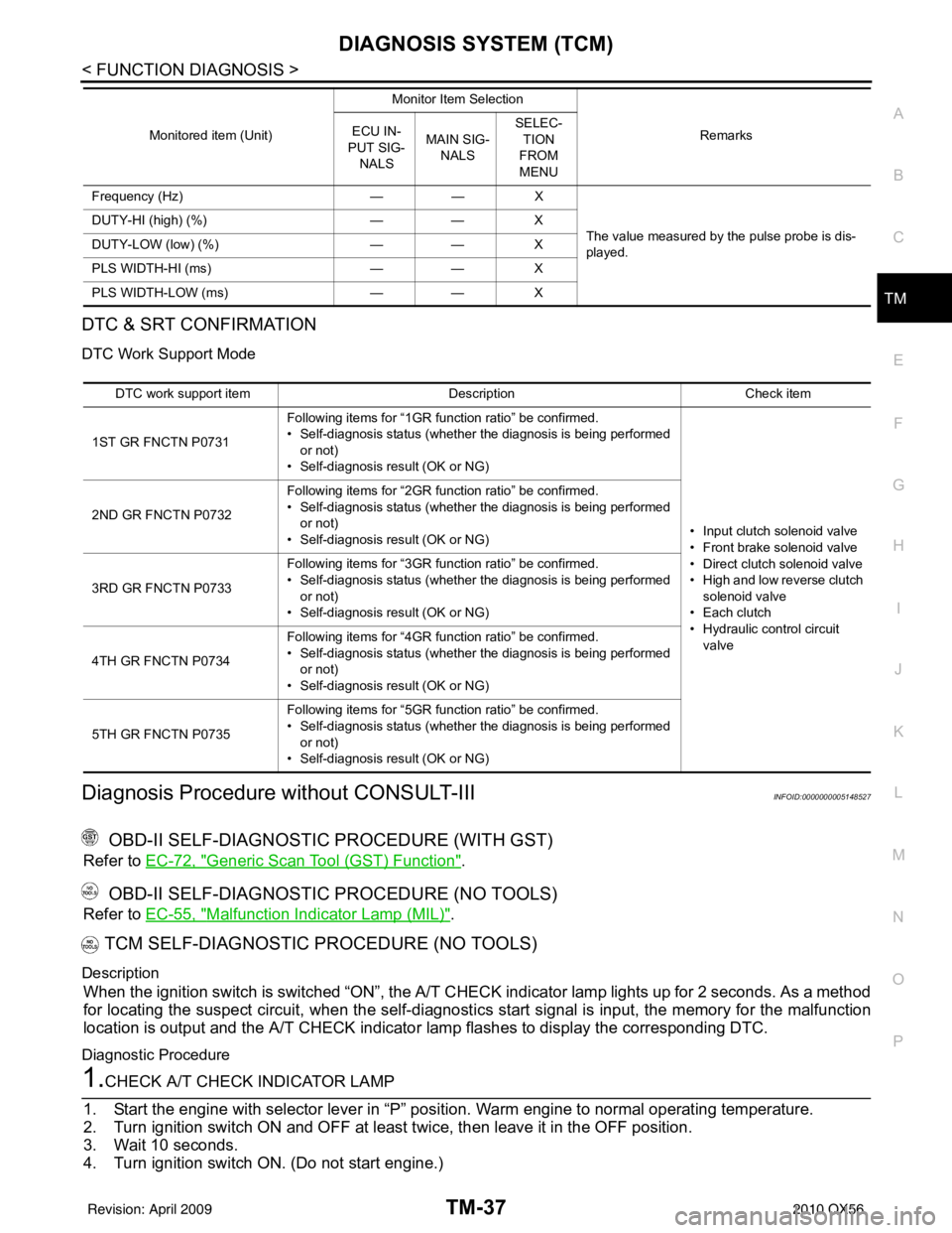
DTC Work Support Mode
Diagnosis Procedure without CONSULT-IIIINFOID:0000000005148527
OBD-II SELF-DIAGNOSTIC PROCEDURE (WITH GST)
Refer to EC-72, "Generic Scan Tool (GST) Function".
OBD-II SELF-DIAGNOSTIC PROCEDURE (NO TOOLS)
Refer to EC-55, "Malfunction Indicator Lamp (MIL)".
TCM SELF-DIAGNOSTIC PROCEDURE (NO TOOLS)
Description
When the ignition switch is switched “ON”, the A/T CHECK indicator lamp lights up for 2 seconds. As a method
for locating the suspect circuit, when the self-diagnosti cs start signal is input, the memory for the malfunction
location is output and the A/T CHECK indicator lamp flashes to display the corresponding DTC.
Diagnostic Procedure
1.CHECK A/T CHECK INDICATOR LAMP
1. Start the engine with selector lever in “P” pos ition. Warm engine to normal operating temperature.
2. Turn ignition switch ON and OFF at least twice, then leave it in the OFF position.
3. Wait 10 seconds.
4. Turn ignition switch ON. (Do not start engine.)
Frequency (Hz) —— X
The value measured by the pulse probe is dis-
played.
DUTY-HI (high) (%)
—— X
DUTY-LOW (low) (%) —— X
PLS WIDTH-HI (ms) —— X
PLS WIDTH-LOW (ms) —— X
Monitored item (Unit)
Monitor Item Selection
Remarks
ECU IN-
PUT SIG- NALS MAIN SIG-
NALS SELEC-
TION
FROM
MENU
DTC work support item DescriptionCheck item
1ST GR FNCTN P0731 Following items for “1GR function ratio” be confirmed.
• Self-diagnosis status (whether the diagnosis is being performed
or not)
• Self-diagnosis result (OK or NG)
• Input clutch solenoid valve
• Front brake solenoid valve
• Direct clutch solenoid valve
• High and low reverse clutch solenoid valve
• Each clutch
• Hydraulic co ntrol circuit
valve
2ND GR FNCTN P0732
Following items for “2GR function ratio” be confirmed.
• Self-diagnosis status (whether the diagnosis is being performed
or not)
• Self-diagnosis result (OK or NG)
3RD GR FNCTN P0733 Following items for “3GR function ratio” be confirmed.
• Self-diagnosis status (whether the diagnosis is being performed
or not)
• Self-diagnosis result (OK or NG)
4TH GR FNCTN P0734 Following items for “4GR function ratio” be confirmed.
• Self-diagnosis status (whether the diagnosis is being performed
or not)
• Self-diagnosis result (OK or NG)
5TH GR FNCTN P0735 Following items for “5GR function ratio” be confirmed.
• Self-diagnosis status (whether the diagnosis is being performed
or not)
• Self-diagnosis result (OK or NG)
Revision: April 20092010 QX56