wheel torque INFINITI QX56 2010 Factory Service Manual
[x] Cancel search | Manufacturer: INFINITI, Model Year: 2010, Model line: QX56, Model: INFINITI QX56 2010Pages: 4210, PDF Size: 81.91 MB
Page 449 of 4210
BR-4
< PRECAUTION >
PRECAUTIONS
5. When the repair work is completed, return the ignition switch to the ″LOCK ″ position before connecting
the battery cables. (At this time, the steering lock mechanism will engage.)
6. Perform a self-diagnosis check of a ll control units using CONSULT-III.
Precaution for Brake SystemINFOID:0000000005147886
• Always use recommended brake fluid. Refer to MA-13, "Fluids and Lubricants".
• Do not reuse drained brake fluid.
• Be careful not to splash brake fluid on painted areas.
• To clean or wash all parts of master cylinder, disc brake caliper and wheel cylinder, use clean brake fluid.
• Do not use mineral oils such as gasoline or kerosene. They will ruin rubber parts of the hydraulic system.
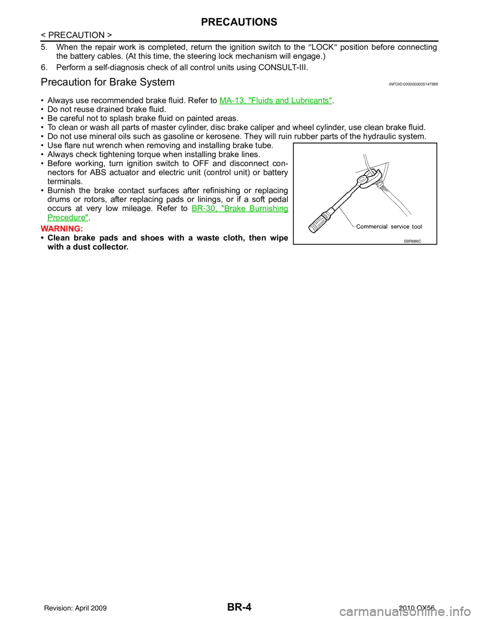
• Use flare nut wrench when removing and installing brake tube.
• Always check tightening torque when installing brake lines.
• Before working, turn ignition switch to OFF and disconnect con- nectors for ABS actuator and electric unit (control unit) or battery
terminals.
• Burnish the brake contact surfaces after refinishing or replacing drums or rotors, after replacing pads or linings, or if a soft pedal
occurs at very low mileage. Refer to BR-30, "
Brake Burnishing
Procedure".
WARNING:
• Clean brake pads and shoes wi th a waste cloth, then wipe
with a dust collector.
SBR686C
Revision: April 20092010 QX56
Page 463 of 4210

BR-18
< ON-VEHICLE MAINTENANCE >
BRAKE FLUID
3. Fully depress brake pedal 4 to 5 times.
4. With brake pedal depressed, loosen bleed valve to let the air out, and then tighten it immediately.
5. Repeat steps 3 and 4 until no more air comes out.
6. Tighten bleed valve to the specified torque. Refer to BR-31, "
Exploded View of Brake Caliper" (front disc
brake), BR-35, "
Exploded View of Brake Caliper" (rear disc brake).
7. Repeat steps 2 through 6 at each wheel, with master cylinder reservoir tank filled at least half way, bleed- ing air in order from the front left, rear left, and front right bleed valves.
Revision: April 20092010 QX56
Page 474 of 4210
FRONT DISC BRAKEBR-29
< ON-VEHICLE REPAIR >
C
DE
G H
I
J
K L
M A
B
BR
N
O P
FRONT DISC BRAKE
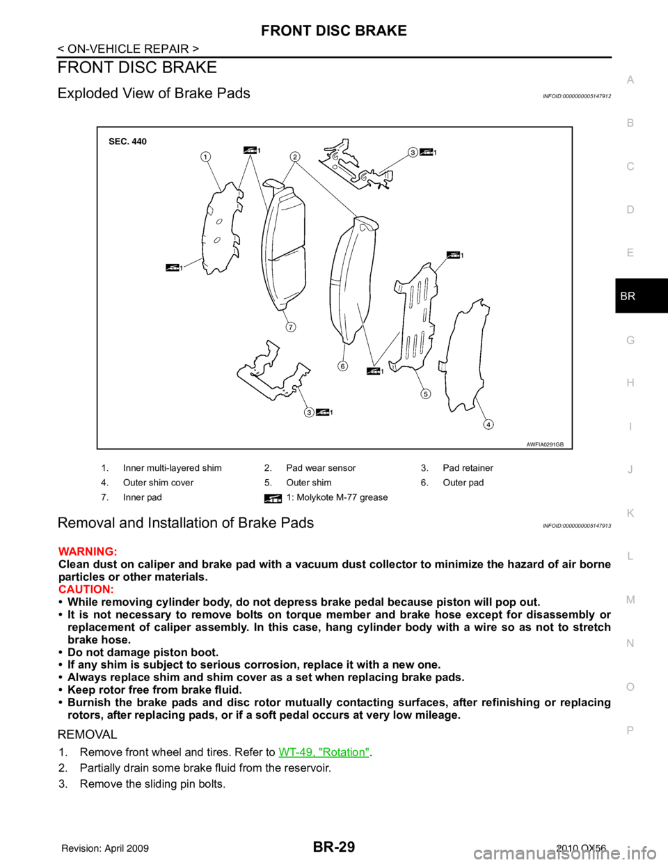
Exploded View of Brake PadsINFOID:0000000005147912
Removal and Installation of Brake PadsINFOID:0000000005147913
WARNING:
Clean dust on caliper and brake pad with a vacuum dust collector to minimize the hazard of air borne
particles or other materials.
CAUTION:
• While removing cylinder bod y, do not depress brake pedal because piston will pop out.
• It is not necessary to remove bolts on torque member and brake hose except for disassembly or replacement of caliper assembly. In this case, hang cylinder body with a wire so as not to stretch
brake hose.
• Do not damage piston boot.
• If any shim is subject to serious corrosion, replace it with a new one.
• Always replace shim and shim cover as a set when replacing brake pads.
• Keep rotor free from brake fluid.
• Burnish the brake pads and disc rotor mutually contacting surfaces, after refinishing or replacing rotors, after replacing pads, or if a so ft pedal occurs at very low mileage.
REMOVAL
1. Remove front wheel and tires. Refer to WT-49, "Rotation".
2. Partially drain some brake fluid from the reservoir.
3. Remove the sliding pin bolts.
1. Inner multi-layered shim 2. Pad wear sensor 3. Pad retainer
4. Outer shim cover 5. Outer shim6. Outer pad
7. Inner pad 1: Molykote M-77 grease
AWFIA0291GB
Revision: April 20092010 QX56
Page 475 of 4210
BR-30
< ON-VEHICLE REPAIR >
FRONT DISC BRAKE
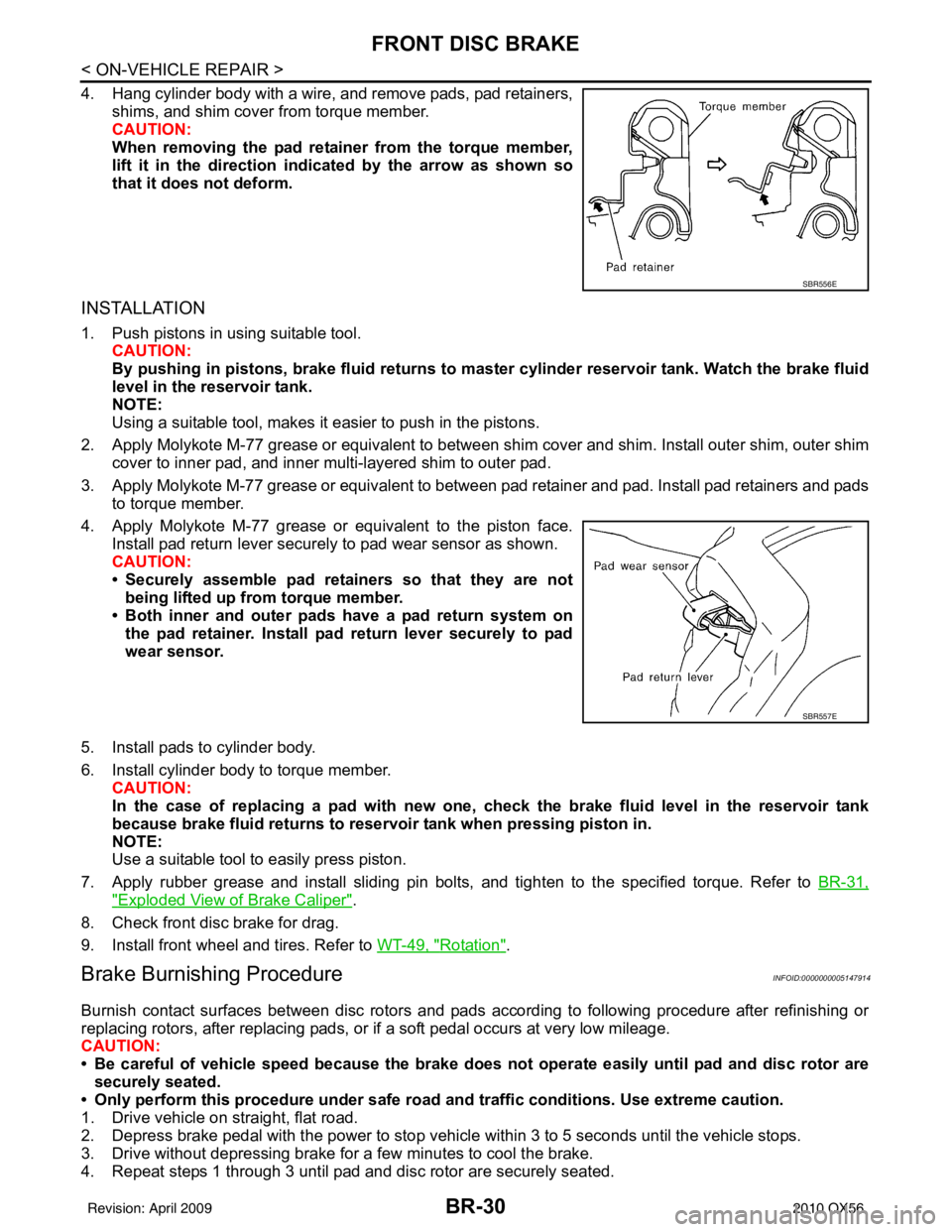
4. Hang cylinder body with a wire, and remove pads, pad retainers,shims, and shim cover from torque member.
CAUTION:
When removing the pad retainer from the torque member,
lift it in the direction indi cated by the arrow as shown so
that it does not deform.
INSTALLATION
1. Push pistons in using suitable tool.
CAUTION:
By pushing in pistons, brake fluid returns to m aster cylinder reservoir tank. Watch the brake fluid
level in the reservoir tank.
NOTE:
Using a suitable tool, makes it easier to push in the pistons.
2. Apply Molykote M-77 grease or equivalent to between shim cover and shim. Install outer shim, outer shim cover to inner pad, and inner multi-layered shim to outer pad.
3. Apply Molykote M-77 grease or equivalent to between pad retainer and pad. Install pad retainers and pads to torque member.
4. Apply Molykote M-77 grease or equivalent to the piston face. Install pad return lever securely to pad wear sensor as shown.
CAUTION:
• Securely assemble pad retainers so that they are not
being lifted up from torque member.
• Both inner and outer pads have a pad return system on
the pad retainer. Install pad return lever securely to pad
wear sensor.
5. Install pads to cylinder body.
6. Install cylinder body to torque member. CAUTION:
In the case of replacing a pad with new one, ch eck the brake fluid level in the reservoir tank
because brake fluid returns to reservoir tank when pressing piston in.
NOTE:
Use a suitable tool to easily press piston.
7. Apply rubber grease and install sliding pin bolts, and tighten to the specified torque. Refer to BR-31,
"Exploded View of Brake Caliper".
8. Check front disc brake for drag.
9. Install front wheel and tires. Refer to WT-49, "
Rotation".
Brake Burnishing ProcedureINFOID:0000000005147914
Burnish contact surfaces between disc rotors and pads according to following procedure after refinishing or
replacing rotors, after replacing pads, or if a soft pedal occurs at very low mileage.
CAUTION:
• Be careful of vehicle speed because the brake does not operate easily until pad and disc rotor are
securely seated.
• Only perform this procedure under safe road and traffic conditions. Use extreme caution.
1. Drive vehicle on straight, flat road.
2. Depress brake pedal with the power to stop vehicle within 3 to 5 seconds until the vehicle stops.
3. Drive without depressing brake for a few minutes to cool the brake.
4. Repeat steps 1 through 3 until pad and disc rotor are securely seated.
SBR556E
SBR557E
Revision: April 20092010 QX56
Page 476 of 4210
FRONT DISC BRAKEBR-31
< ON-VEHICLE REPAIR >
C
DE
G H
I
J
K L
M A
B
BR
N
O P
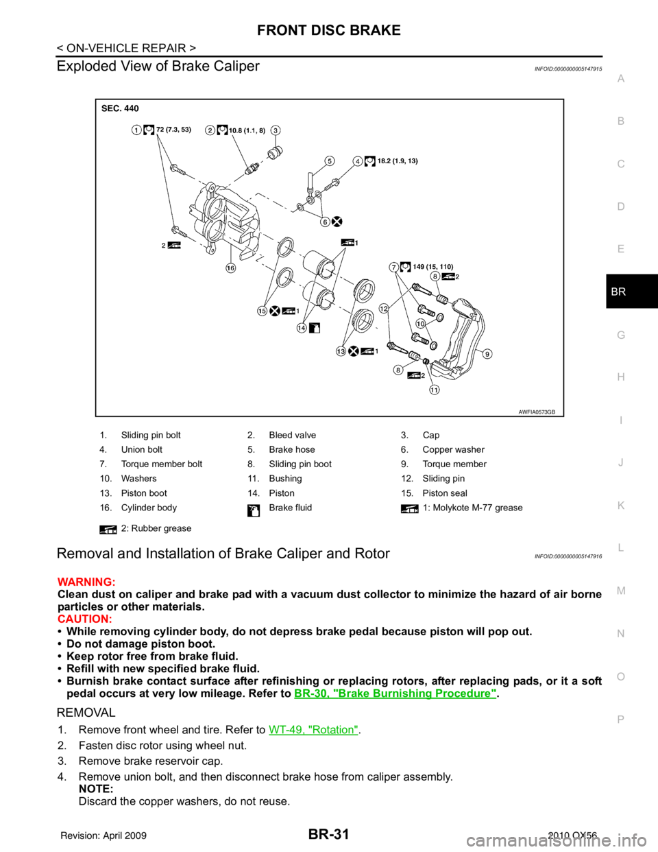
Exploded View of Brake CaliperINFOID:0000000005147915
Removal and Installation of Brake Caliper and RotorINFOID:0000000005147916
WARNING:
Clean dust on caliper and brake pad with a vacuum dust collector to minimize the hazard of air borne
particles or other materials.
CAUTION:
• While removing cylinder bod y, do not depress brake pedal because piston will pop out.
• Do not damage piston boot.
• Keep rotor free from brake fluid.
• Refill with new specified brake fluid.
• Burnish brake contact surface after refinishing or replacing rotors, after replacing pads, or it a soft
pedal occurs at very low mileage. Refer to BR-30, "
Brake Burnishing Procedure".
REMOVAL
1. Remove front wheel and tire. Refer to WT-49, "Rotation".
2. Fasten disc rotor using wheel nut.
3. Remove brake reservoir cap.
4. Remove union bolt, and then disconnect brake hose from caliper assembly. NOTE:
Discard the copper washers, do not reuse.
1. Sliding pin bolt 2. Bleed valve 3. Cap
4. Union bolt 5. Brake hose 6. Copper washer
7. Torque member bolt 8. Sliding pin boot 9. Torque member
10. Washers 11. Bushing 12. Sliding pin
13. Piston boot 14. Piston 15. Piston seal
16. Cylinder body Brake fluid1: Molykote M-77 grease
2: Rubber grease
AWFIA0573GB
Revision: April 20092010 QX56
Page 477 of 4210
BR-32
< ON-VEHICLE REPAIR >
FRONT DISC BRAKE
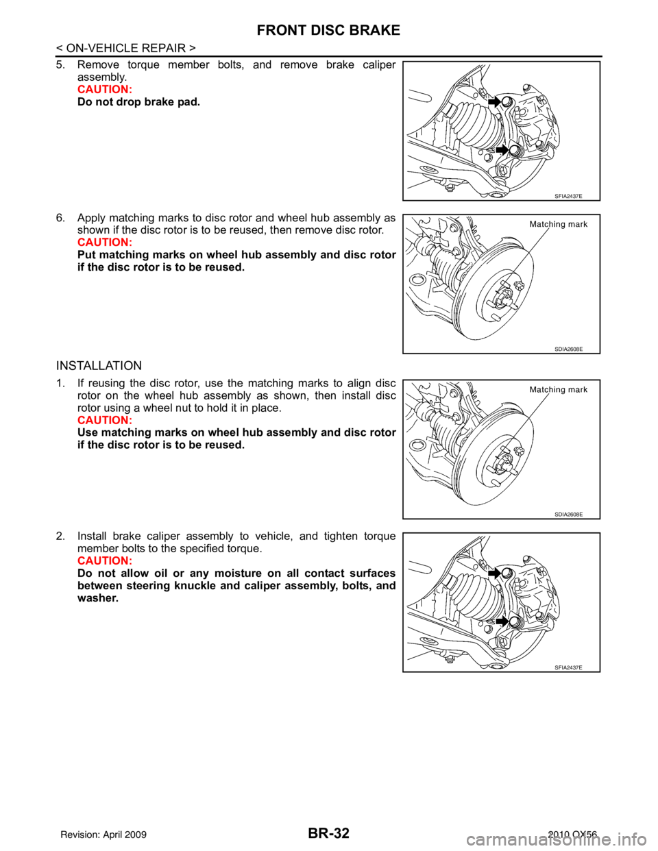
5. Remove torque member bolts, and remove brake caliperassembly.
CAUTION:
Do not drop brake pad.
6. Apply matching marks to disc rotor and wheel hub assembly as shown if the disc rotor is to be reused, then remove disc rotor.
CAUTION:
Put matching marks on wheel hub assembly and disc rotor
if the disc rotor is to be reused.
INSTALLATION
1. If reusing the disc rotor, use the matching marks to align discrotor on the wheel hub assembly as shown, then install disc
rotor using a wheel nut to hold it in place.
CAUTION:
Use matching marks on wheel hub assembly and disc rotor
if the disc rotor is to be reused.
2. Install brake caliper assembly to vehicle, and tighten torque member bolts to the specified torque.
CAUTION:
Do not allow oil or any moisture on all contact surfaces
between steering knuckle and caliper assembly, bolts, and
washer.
SFIA2437E
SDIA2608E
SDIA2608E
SFIA2437E
Revision: April 20092010 QX56
Page 478 of 4210
FRONT DISC BRAKEBR-33
< ON-VEHICLE REPAIR >
C
DE
G H
I
J
K L
M A
B
BR
N
O P
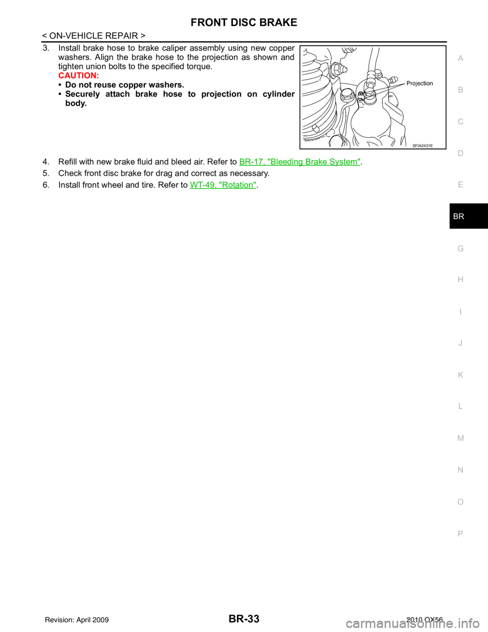
3. Install brake hose to brake caliper assembly using new copper washers. Align the brake hose to the projection as shown and
tighten union bolts to the specified torque.
CAUTION:
• Do not reuse copper washers.
• Securely attach brake hose to projection on cylinderbody.
4. Refill with new brake fluid and bleed air. Refer to BR-17, "
Bleeding Brake System".
5. Check front disc brake for drag and correct as necessary.
6. Install front wheel and tire. Refer to WT-49, "
Rotation".
SFIA2431E
Revision: April 20092010 QX56
Page 506 of 4210
![INFINITI QX56 2010 Factory Service Manual BRC-14
< FUNCTION DIAGNOSIS >[VDC/TCS/ABS]
TCS
TCS
System DiagramINFOID:0000000005147950
System DescriptionINFOID:0000000005147951
• Traction Control System is a function that electronically control INFINITI QX56 2010 Factory Service Manual BRC-14
< FUNCTION DIAGNOSIS >[VDC/TCS/ABS]
TCS
TCS
System DiagramINFOID:0000000005147950
System DescriptionINFOID:0000000005147951
• Traction Control System is a function that electronically control](/img/42/57032/w960_57032-505.png)
BRC-14
< FUNCTION DIAGNOSIS >[VDC/TCS/ABS]
TCS
TCS
System DiagramINFOID:0000000005147950
System DescriptionINFOID:0000000005147951
• Traction Control System is a function that electronically controls engine torque, brake fluid pressure and A/T
gear position to ensure the optimum slippage ratio at drive wheels by computing wheel speed signals from 4
wheel sensors. When ABS actuator and electric unit (control unit) detects a spin at drive wheels (rear
wheels), it compares wheel speed signals from all 4 wheels. At this time, LH and RH rear brake fluid pres-
sure are controlled, while fuel being cut to engine and throttle valve being closed to reduce engine torque by
the control unit. Further more, throttle position is continuously controlled to ensure the optimum engine
torque at all times.
• During TCS operation, it informs driver of syst em operation by flashing SLIP indicator lamp.
• Electrical system diagnosis by CONSULT-III is available.
AWFIA0065GB
Revision: April 20092010 QX56
Page 603 of 4210
![INFINITI QX56 2010 Factory Service Manual PRECAUTIONSBRC-111
< PRECAUTION > [VDC/TCS/ABS]
C
D
E
G H
I
J
K L
M A
B
BRC
N
O P
5. When the repair work is completed, return the ignition switch to the ″LOCK ″ position before connecting
the ba INFINITI QX56 2010 Factory Service Manual PRECAUTIONSBRC-111
< PRECAUTION > [VDC/TCS/ABS]
C
D
E
G H
I
J
K L
M A
B
BRC
N
O P
5. When the repair work is completed, return the ignition switch to the ″LOCK ″ position before connecting
the ba](/img/42/57032/w960_57032-602.png)
PRECAUTIONSBRC-111
< PRECAUTION > [VDC/TCS/ABS]
C
D
E
G H
I
J
K L
M A
B
BRC
N
O P
5. When the repair work is completed, return the ignition switch to the ″LOCK ″ position before connecting
the battery cables. (At this time, the steering lock mechanism will engage.)
6. Perform a self-diagnosis check of al l control units using CONSULT-III.
Precaution for Brake SystemINFOID:0000000005148094
CAUTION:
• Always use recommended brake fluid. Refer to MA-13, "
Fluids and Lubricants".
• Never reuse drained brake fluid.
• Be careful not to splash brake fluid on painted areas; it may cause paint damage. If brake fluid is
splashed on painted areas, wash it away with water immediately.
• To clean or wash all parts of master cylin der and disc brake caliper, use clean brake fluid.
• Never use mineral oils such as gasoline or kerosen e. They will ruin rubber parts of the hydraulic sys-
tem.
• Use flare nut wrench when removing and installing brake
tube.
• If a brake fluid leak is found, the part must be disassembled
without fail. Then it has to be replaced with a new one if a
defect exists.
• Turn the ignition switch OFF and remove the connector of the ABS actuator and electric unit (con trol unit) or the battery ter-
minal before performing the work.
• Always torque brake lines when installing.
• Burnish the brake contact surf aces after refinishing or replac-
ing rotors, after replacing pads, or if a soft pedal occurs at
very low mileage.
Refer to BR-30, "
Brake Burnishing Procedure" (front disc brake) or BR-35, "Brake Burnishing Proce-
dure" (rear disc brake).
WARNING:
• Clean brake pads and shoes with a waste cl oth, then wipe with a dust collector.
Precaution for Brake ControlINFOID:0000000005148095
• During ABS operation, the brake pedal may vibrate lightly and a mechanical noise may be heard. This is
normal.
• Just after starting vehicle, the brake pedal may vibrate or a motor operating noise may be heard from engine
compartment. This is a normal status of operation check.
• Stopping distance may be longer than that of vehicles without ABS when vehicle drives on rough, gravel, or snow-covered (fresh, deep snow) roads.
• When an error is indicated by ABS or another warning lamp, collect all necessary information from customer (what symptoms are present under what conditions) and check for simple causes before starting diagnosis.
Besides electrical system inspection, check boos ter operation, brake fluid level, and fluid leaks.
• If incorrect tire sizes or types are installed on the vehicle or brake pads are not Genuine NISSAN parts, stop-
ping distance or steering stability may deteriorate.
• If there is a radio, antenna or related wiring near control module, ABS function may have a malfunction or
error.
• If aftermarket parts (car stereo, CD player, etc.) have been installed, check for incidents such as harness pinches, open circuits or improper wiring.
• If the following components are replaced with non-genuine components or modified, the VDC OFF indicator lamp and SLIP indicator lamp may turn on or the VDC system may not operate properly. Components
related to suspension (shock absorbers, struts, springs , bushings, etc.), tires, wheels (exclude specified
size), components related to brake system (pads, roto rs, calipers, etc.), components related to engine (muf-
fler, ECM, etc.), components related to body reinforcement (roll bar, tower bar, etc.).
• Driving with broken or excessively worn suspensi on components, tires or brake system components may
cause the VDC OFF indicator lamp and the SLIP indicator lamp to turn on, and the VDC system may not
operate properly.
• When the TCS or VDC is activated by sudden acceleration or sudden turn, some noise may occur. The noise is a result of the normal operation of the TCS and VDC.
• When driving on roads which have extreme slopes (such as mountainous roads) or high banks (such as sharp curves on a freeway), the VDC may not operate no rmally, or the VDC warning lamp and the SLIP indi-
cator lamp may turn on. This is not a problem if normal operation can be resumed after restarting the engine.
SBR686C
Revision: April 20092010 QX56
Page 605 of 4210
![INFINITI QX56 2010 Factory Service Manual PREPARATIONBRC-113
< PREPARATION > [VDC/TCS/ABS]
C
D
E
G H
I
J
K L
M A
B
BRC
N
O P
PREPARATION
PREPARATION
Special Service ToolINFOID:0000000005148097
The actual shapes of Kent-Moore tools may differ INFINITI QX56 2010 Factory Service Manual PREPARATIONBRC-113
< PREPARATION > [VDC/TCS/ABS]
C
D
E
G H
I
J
K L
M A
B
BRC
N
O P
PREPARATION
PREPARATION
Special Service ToolINFOID:0000000005148097
The actual shapes of Kent-Moore tools may differ](/img/42/57032/w960_57032-604.png)
PREPARATIONBRC-113
< PREPARATION > [VDC/TCS/ABS]
C
D
E
G H
I
J
K L
M A
B
BRC
N
O P
PREPARATION
PREPARATION
Special Service ToolINFOID:0000000005148097
The actual shapes of Kent-Moore tools may differ from those of special service tools illustrated here.
Commercial Service ToolINFOID:0000000005148098
Tool number
(Kent-Moore No.)
Tool name Description
KV991J0080
(J-45741)
ABS active wheel sensor tester Checking operation of ABS active wheel sen-
sors
WFIA0101E
Tool name
Description
1. Flare nut crowfoot
2. Torque wrench Removing and installing brake piping
a: 10 mm (0.39 in)/12 mm (0.47 in)
S-NT360
Revision: April 20092010 QX56