heater INFINITI QX56 2011 Factory Service Manual
[x] Cancel search | Manufacturer: INFINITI, Model Year: 2011, Model line: QX56, Model: INFINITI QX56 2011Pages: 5598, PDF Size: 94.53 MB
Page 1 of 5598
A
B
D
E
F
G
H
I
J
K
L
M
N
P
O
C
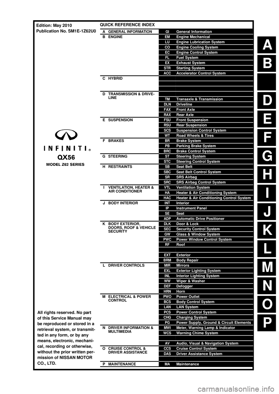
QUICK REFERENCE INDEX
AGENERAL INFORMATIONGIGeneral Information
BENGINEEMEngine Mechanical
LUEngine Lubrication System
COEngine Cooling System
ECEngine Control System
FLFuel System
EXExhaust System
STRStarting System
ACCAccelerator Control System
CHYBRIDHBCHybrid Control System
HBBHybrid Battery System
HBRHybrid Brake System
DTRANSMISSION & DRIVE-
LINECLClutch
TMTransaxle & Transmission
DLNDriveline
FAXFront Axle
RAXRear Axle
ESUSPENSIONFSUFront Suspension
RSURear Suspension
SCSSuspension Control System
WTRoad Wheels & Tires
FBRAKESBRBrake System
PBParking Brake System
BRCBrake Control System
GSTEERINGSTSteering System
STCSteering Control System
HRESTRAINTSSBSeat Belt
SBCSeat Belt Control System
SRSRS Airbag
SRCSRS Airbag Control System
IVENTILATION, HEATER &
AIR CONDITIONERVTLVentilation System
HAHeater & Air Conditioning System
HACHeater & Air Conditioning Control System
JBODY INTERIORINTInterior
IPInstrument Panel
SESeat
ADPAutomatic Drive Positioner
KBODY EXTERIOR,
DOORS, ROOF & VEHICLE
SECURITYDLKDoor & Lock
SECSecurity Control System
GWGlass & Window System
PWCPower Window Control System
RFRoof
HDHood
EXTExterior
BRMBody Repair
LDRIVER CONTROLSMIRMirrors
EXLExterior Lighting System
INLInterior Lighting System
WWWiper & Washer
DEFDefogger
HRNHorn
MELECTRICAL & POWER
CONTROLPWOPower Outlet
BCSBody Control System
LANLAN System
PCSPower Control System
CHGCharging System
PGPower Supply, Ground & Circuit Elements
NDRIVER INFORMATION &
MULTIMEDIAMWIMeter, Warning Lamp & Indicator
WCSWarning Chime System
SNSonar System
AVAudio, Visual & Navigation System
OCRUISE CONTROL &
DRIVER ASSISTANCECCSCruise Control System
DASDriver Assistance System
DMSDrive Mode System
PMAINTENANCEMAMaintenance
All rights reserved. No part
of this Service Manual may
be reproduced or stored in a
retrieval system, or transmit-
ted in any form, or by any
means, electronic, mechani-
cal, recording or otherwise,
without the prior written per-
mission of NISSAN MOTOR
CO., LTD.
Edition: May 2010
Publication No. SM1E-1Z62U0
Page 951 of 5598
ENGINE COOLANTCO-9
< PERIODIC MAINTENANCE >
C
DE
F
G H
I
J
K L
M A
CO
NP
O
3. Check drained engine coolant for contaminants such as rust, corrosion or discoloration.
If contaminated, flush the engine cooling system. Refer to CO-10, "
Flushing".
RefillingINFOID:0000000006289659
1. Install reservoir tank if removed, and radiator drain plug.
CAUTION:
Be sure to clean drain plug and install with new O-ring. Refer to CO-13, "
Exploded View".
If water drain plug on cylinder block is removed, close and tighten it. Refer to EM-107, "
Disassem-
bly and Assembly".
2. Check that each hose clamp is firmly tightened.
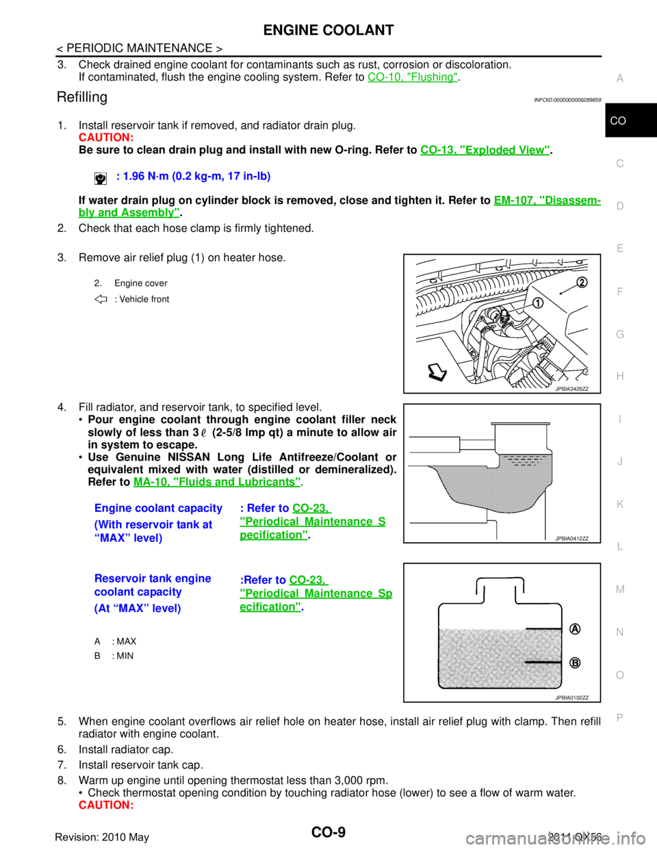
3. Remove air relief plug (1) on heater hose.
4. Fill radiator, and reservoir tank, to specified level. Pour engine coolant through engine coolant filler neck
slowly of less than 3 (2-5/8 lmp qt) a minute to allow air
in system to escape.
Use Genuine NISSAN Long Li fe Antifreeze/Coolant or
equivalent mixed with water (dis tilled or demineralized).
Refer to MA-10, "
Fluids and Lubricants".
5. When engine coolant overflows air relief hole on heater hos e, install air relief plug with clamp. Then refill
radiator with engine coolant.
6. Install radiator cap.
7. Install reservoir tank cap.
8. Warm up engine until opening thermostat less than 3,000 rpm. Check thermostat opening condition by touching radiat or hose (lower) to see a flow of warm water.
CAUTION: : 1.96 N·m (0.2 kg-m, 17 in-lb)
2. Engine cover
: Vehicle front
JPBIA3429ZZ
Engine coolant capacity : Refer to CO-23,
"PeriodicalMaintenanceS
pecification".
(With reservoir tank at
“MAX” level)JPBIA0412ZZ
Reservoir tank engine
coolant capacity :Refer to
CO-23,
"PeriodicalMaintenanceSp
ecification".
(At “MAX” level)
A : MAX
B: MIN
JPBIA0102ZZ
Revision: 2010 May2011 QX56
Page 952 of 5598
CO-10
< PERIODIC MAINTENANCE >
ENGINE COOLANT
Watch water temperature gauge so as not to overheat engine.
9. Stop the engine and cool down to less than approximately 50 °C (122 °F).
Cool down using fan to reduce the time.
If necessary, refill radiator up to filler neck with engine coolant.
10. Refill reservoir tank to “MAX” level line with engine coolant if necessary.
11. Repeat steps 6 through 10 two or more times with reservoir tank cap installed until engine coolant level no longer drops.
12. Check cooling system for leakage with engine running.
13. Warm up the engine, and check for sound of engine coolant flow while running engine from idle up to 3,000 rpm with heater temperature controller set at several position between “COOL” and “WARM”.
Sound may be noticeable at heater unit.
14. Repeat step 13 three times.
15. If sound is heard, bleed air from cooling system by repeating step 4, and steps from 6 to 14 until engine
coolant level no longer drops.
FlushingINFOID:0000000006289660
1. Install reservoir tank if removed, and radiator drain plug. CAUTION:
Be sure to clean drain plug and install with new O-ring. Refer to CO-13, "
Exploded View".
If water drain plug on cylinder block is removed, close and tighten it. Refer to EM-107, "
Disassem-
bly and Assembly".
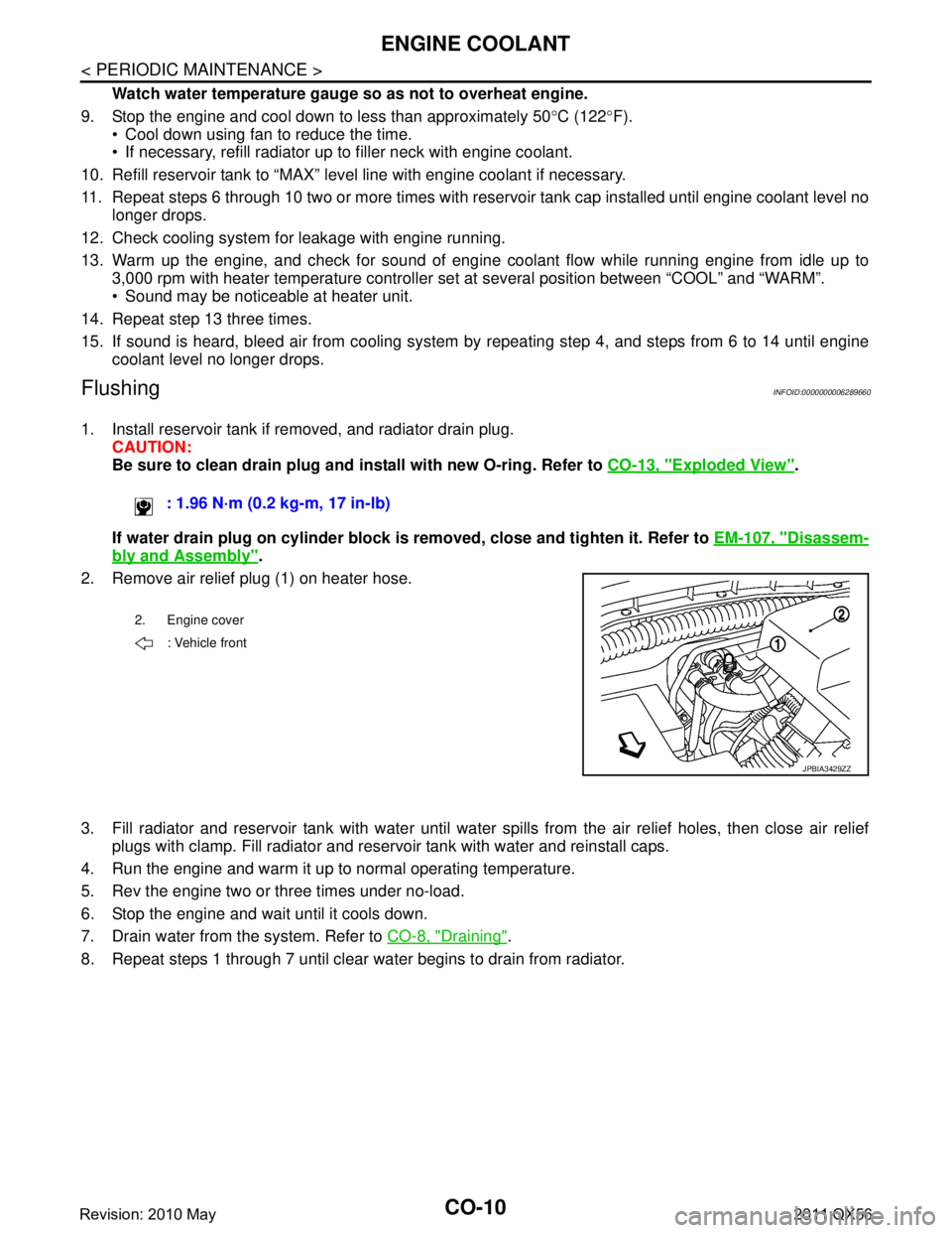
2. Remove air relief plug (1) on heater hose.
3. Fill radiator and reservoir tank with water until water spills from the air relief holes, then close air relief
plugs with clamp. Fill radiator and reservoir tank with water and reinstall caps.
4. Run the engine and warm it up to normal operating temperature.
5. Rev the engine two or three times under no-load.
6. Stop the engine and wait until it cools down.
7. Drain water from the system. Refer to CO-8, "
Draining".
8. Repeat steps 1 through 7 until clear water begins to drain from radiator. : 1.96 N·m (0.2 kg-m, 17 in-lb)
2. Engine cover
: Vehicle front
JPBIA3429ZZ
Revision: 2010 May2011 QX56
Page 962 of 5598
CO-20
< REMOVAL AND INSTALLATION >
WATER INLET AND THERMOSTAT ASSEMBLY
WATER INLET AND THERMOSTAT ASSEMBLY
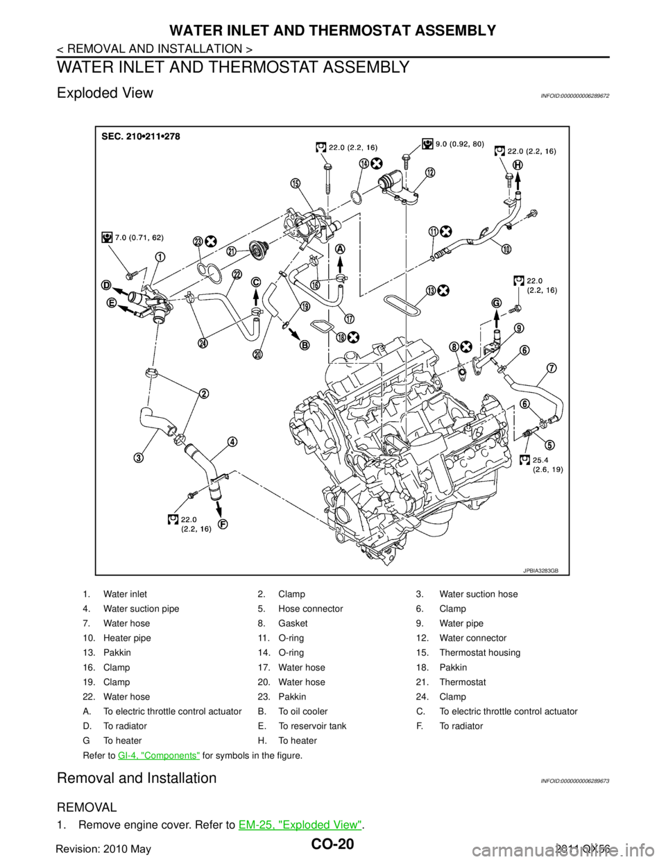
Exploded ViewINFOID:0000000006289672
Removal and InstallationINFOID:0000000006289673
REMOVAL
1. Remove engine cover. Refer to EM-25, "Exploded View".
1. Water inlet 2. Clamp 3. Water suction hose
4. Water suction pipe 5. Hose connector 6. Clamp
7. Water hose 8. Gasket 9. Water pipe
10. Heater pipe 11. O-ring 12. Water connector
13. Pakkin 14. O-ring 15. Thermostat housing
16. Clamp 17. Water hose 18. Pakkin
19. Clamp 20. Water hose 21. Thermostat
22. Water hose 23. Pakkin 24. Clamp
A. To electric throttle control actuator B. To o il cooler C. To electric throttle control actuator
D. To radiator E. To reservoir tank F. To radiator
G To heater H. To heater
Refer to GI-4, "
Components" for symbols in the figure.
JPBIA3283GB
Revision: 2010 May2011 QX56
Page 963 of 5598
WATER INLET AND THERMOSTAT ASSEMBLYCO-21
< REMOVAL AND INSTALLATION >
C
DE
F
G H
I
J
K L
M A
CO
NP
O
2. Remove front under cover with power tool. Refer to
EXT-25, "Exploded View".
3. Drain engine coolant from drain plugs on radiator and cylinder block. Refer to CO-8, "
Draining" and EM-
103, "Setting".
CAUTION:
Perform this step when engine is cold.
Never spill engine coolant on drive belts.
4. Disconnect radiator hose (upper and lower). Refer to CO-13, "
Exploded View".
5. Remove intake manifold. Refer to EM-30, "
Exploded View".
6. Remove fuel feed tube. Refer to EM-43, "
Exploded View".
7. Remove water hose, water connector, heater pipes and heater hoses.
8. Remove thermostat housing.
9. Remove water inlet and thermostat.
INSTALLATION
Note the following, and install in the reverse order of removal.
CAUTION:
Be careful not to spill engine coolant over en gine room. Use rag to absorb engine coolant.
Thermostat
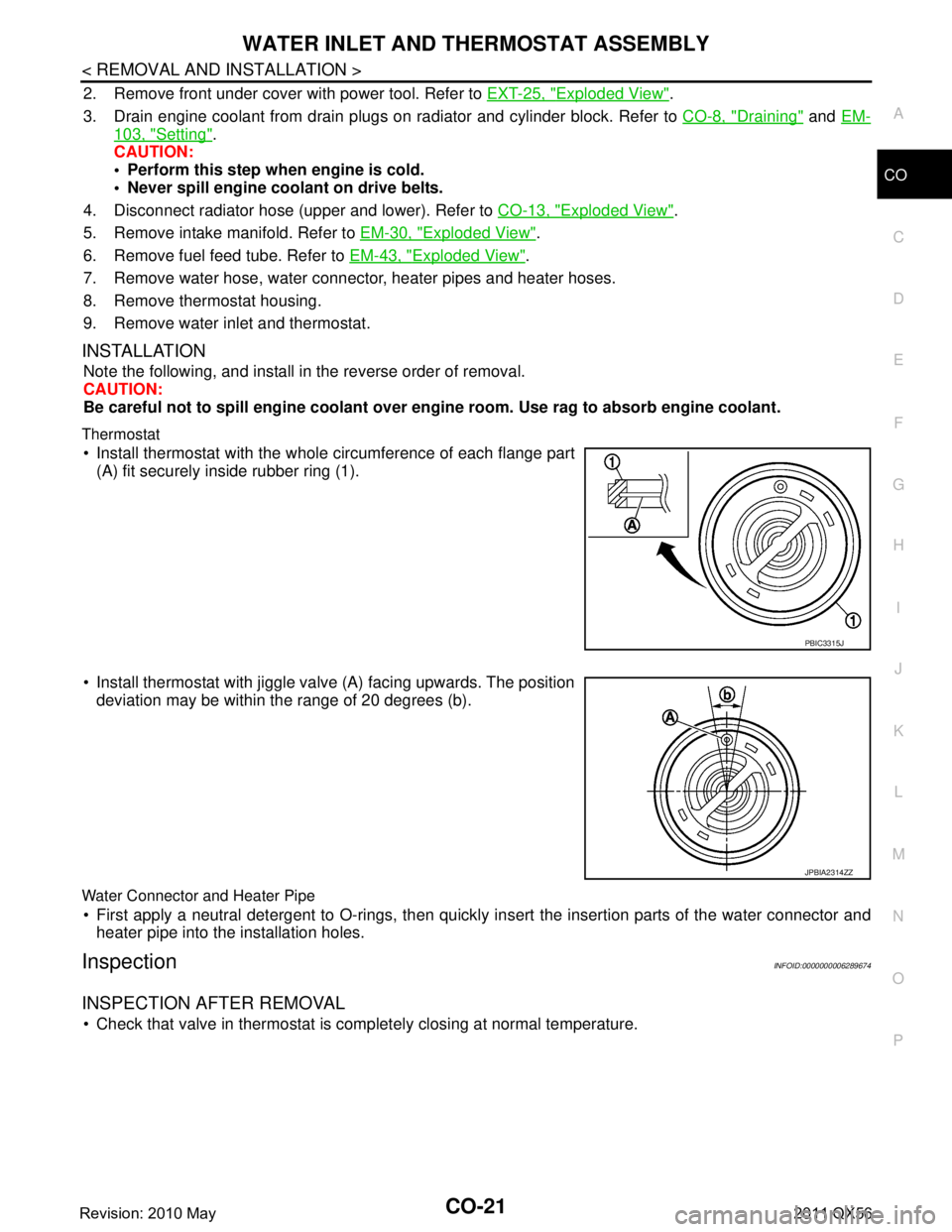
Install thermostat with the whole circumference of each flange part
(A) fit securely inside rubber ring (1).
Install thermostat with jiggle valve (A) facing upwards. The position deviation may be within the range of 20 degrees (b).
Water Connector and Heater Pipe
First apply a neutral detergent to O-rings, then quickly in sert the insertion parts of the water connector and
heater pipe into the installation holes.
InspectionINFOID:0000000006289674
INSPECTION AFTER REMOVAL
Check that valve in thermostat is co mpletely closing at normal temperature.
PBIC3315J
JPBIA2314ZZ
Revision: 2010 May2011 QX56
Page 1788 of 5598
DLK-252
< REMOVAL AND INSTALLATION >
CAB MOUNTING INSULATOR
Drain brake fluid from brake line. Refer to BR-10, "Draining".
Release fuel pressure. Refer to EC-153, "
Work Procedure".
Disconnect both battery cables. Refer to PG-164, "
Removal and Installation".
Drain engine coolant from radiator. Refer to CO-8, "
Draining".
Discharge refrigerant from A/C circuit. Refer to HA-20, "
Recycle Refrigerant".
Drain power steering fluid from reservoir tank.
4. Remove parts relating to connection of body assembly and frame assembly. Tire and wheel: Refer to WT-64, "
Removal and Installation" (with TPMS).
Front fender protector (LH and RH): Refer to EXT-23, "
FENDER PROTECTOR : Removal and Installa-
tion".
Front bumper: Refer to EXT-13, "
Removal and Installation".
Radiator core support upper: Refer to DLK-220, "
Removal and Installation".
Fan shroud: Refer to CO-16, "
Removal and Installation".
Battery and battery case: Refer to PG-164, "
Removal and Installation".
Air cleaner case (upper and lower): Refer to EM-27, "
Removal and Installation".
Engine cover: Refer to EM-25, "
Removal and Installation".
Rear wheel house protector (LH and RH): EXT-24, "
REAR WHEEL HOUSE PROTECTOR : Removal
and Installation".
Rear bumper: Refer to EXT-17, "
Removal and Installation".
Fuel filler tube: Remove to FL-8, "
Exploded View".
Spare tire
Towing hook bracket.
5. Separate parts relating to connection of body assembly and frame assembly. Vehicle front
Disconnect ICC sensor connector. (models with ICC) Refer to CCS-176, "
Removal and Installation".
Remove radiator upper hose and radiator lower hose from radiator assembly. Refer to CO-13,
"Exploded View".
Remove A/T fluid cooler hose B and A/T fluid cooler hose E from A/T fluid cooler tubes. Refer to TM-
202, "Exploded View".
Remove power steering return hose from oil cooler, and then power steering return hose clamp bolt from frame assembly. Refer to ST-54, "
Exploded View".
Remove power steering suction hose from reservoir tank. Refer to ST-54, "
Exploded View".
CAUTION:
Never spill power steering fluid in engine room.
Remove A/C low-presser flexible hose from A/C low-presser pipe. Refer to HA-35, "
LOW-PRESSURE
FLEXIBLE HOSE : Removal and Installation".
Remove A/C hi-presser flexible hose from condenser. Refer to HA-34, "
HIGH-PRESSURE FLEXIBLE
HOSE : Removal and Installation".
Remove all engine Control Harness connectors, har ness clips and others that are connected to the
body assembly side of the engine room. (engine room LH and RH side). Refer to PG-148, "
Engine Con-
trol Harness".
NOTE:
Separate harness connectors from ECM (engine control module). Refer to EC-10, "
General Precau-
tions".
CAUTION:
When pulling out harnesses, never damage harnesses or connectors.
After temporarily securing connectors, cover th em with vinyl or similar material to protect
against adhesion of foreign materials.
Disconnect engine room harness connectors and remo ve harness clips from engine assembly (engine
RH side). Refer to PG-146, "
Engine Room Harness".
Remove heater hoses from front water outlet tube (engine room RH side). Refer to HA-33, "
Exploded
View".
Disconnect front wheel sensor connectors (LH and RH). Refer to BRC-134, "
FRONT WHEEL SENSOR
: Exploded View".
Disconnect fuel feed tube and EVAP hos e (front wheel well LH side).
Remove steering lower shaft from steering gear side assembly. Refer to ST-37, "
Removal and Installa-
tion"
CAUTION:
Spiral cable may be cut if steering wheel turns while separating steering column assembly and
steering gear assembly.
Revision: 2010 May2011 QX56
Page 2027 of 5598

EC-3
C
DE
F
G H
I
J
K L
M
EC A
N
O P
Work Procedure ..................................................
..
147
IDLE AIR VOLUME LEARNING ......................148
Description .......................................................... ..148
Work Procedure ....................................................148
VVEL CONTROL SHAFT POSITION SEN-
SOR ADJUSTMENT .........................................
150
Description .......................................................... ..150
Work Procedure ....................................................150
MIXTURE RATIO SELF-LEARNING VALUE
CLEAR ..............................................................
152
Description .......................................................... ..152
Work Procedure ....................................................152
FUEL PRESSURE .......................................... ..153
Work Procedure .................................................. ..153
HOW TO SET SRT CODE ................................156
Description .......................................................... ..156
SRT Set Driving Pattern ........................................157
Work Procedure ....................................................159
DTC/CIRCUIT DIAGNOSIS .......................161
TROUBLE DIAGNOSIS - SPECIFICATION
VALUE ............................................................ ..
161
Description .......................................................... ..161
Component Function Check ..................................161
Diagnosis Procedure .............................................162
POWER SUPPLY AND GROUND CIRCUIT ....168
Diagnosis Procedure ........................................... ..168
U0101 CAN COMM CIRCUIT ...........................171
DTC Logic ........................................................... ..171
Diagnosis Procedure .............................................171
U1001 CAN COMM CIRCUIT ...........................172
DTC Logic ........................................................... ..172
Diagnosis Procedure .............................................172
U0113, U1003 CAN COMM CIRCUIT ..............173
DTC Logic ........................................................... ..173
Diagnosis Procedure .............................................173
U1024 CAN COMM CIRCUIT ...........................175
DTC Logic ........................................................... ..175
Diagnosis Procedure .............................................175
P0011, P0021 IVT CONTROL ..........................177
DTC Logic ........................................................... ..177
Diagnosis Procedure .............................................178
Component Inspection (Intake Valve Timing Con-
trol Solenoid Valve) ...............................................
179
P0031, P0032, P0051, P0052 A/F SENSOR 1
HEATER ...........................................................
181
DTC Logic ........................................................... ..181
Diagnosis Procedure .............................................181
Component Inspection (A/F Sensor 1 Heater) ......182
P0037, P0038, P0057, P0058 HO2S2 HEAT-
ER ....................................................................
184
DTC Logic ............................................................ ..184
Diagnosis Procedure .............................................184
Component Inspection (HO2 Sensor 2 Heater) .....186
P006A, P0101 MAF SENSOR ........................187
DTC Logic ..............................................................187
Diagnosis Procedure .............................................188
Component Inspection (MAF Sensor) ...................190
P0075, P0081 IVT CONTROL SOLENOID
VALVE .............................................................
193
DTC Logic ..............................................................193
Diagnosis Procedure .............................................193
Component Inspection (Intake Valve Timing Con-
trol Solenoid Valve) ...............................................
194
P0087, P0088, P0090 FRP CONTROL SYS-
TEM .................................................................
195
DTC Logic ..............................................................195
Diagnosis Procedure .............................................196
Component Inspection ...........................................196
P008A LOW FUEL PRESSURE CONTROL
SYSTEM ..........................................................
198
DTC Logic ............................................................ ..198
Diagnosis Procedure .............................................198
P008B LOW FUEL PRESSURE CONTROL
SYSTEM ..........................................................
200
DTC Logic ............................................................ ..200
Diagnosis Procedure .............................................200
P0102, P0103 MAF SENSOR .........................201
DTC Logic ..............................................................201
Diagnosis Procedure .............................................201
Component Inspection (MAF Sensor) ...................203
P0106 MANIFOLD ABSOLUTE PRESSURE
SENSOR ..........................................................
206
DTC Logic ..............................................................206
Diagnosis Procedure .............................................207
Component Inspection (MAP Sensor) ...................208
P010A MANIFOLD ABSOLUTE PRESSURE
SENSOR ..........................................................
210
DTC Logic ..............................................................210
Diagnosis Procedure .............................................210
Component Inspection (MAP Sensor) ...................211
P0112, P0113 IAT SENSOR ...........................213
DTC Logic ..............................................................213
Diagnosis Procedure .............................................213
Component Inspection (Intake Air Temperature
Sensor) ..................................................................
214
P0116 ECT SENSOR ......................................215
DTC Logic ..............................................................215
Diagnosis Procedure .............................................215
Revision: 2010 May2011 QX56
Page 2044 of 5598
![INFINITI QX56 2011 Factory Service Manual
EC-20
< SYSTEM DESCRIPTION >[VK56VD]
COMPONENT PARTS
High pressure fuel pump
EC-28, "High Pressure Fuel Pump"
Low pressure fuel pumpEC-30, "Low Pressure Fuel Pump"
Fuel pump control module (FPCM)EC-2 INFINITI QX56 2011 Factory Service Manual
EC-20
< SYSTEM DESCRIPTION >[VK56VD]
COMPONENT PARTS
High pressure fuel pump
EC-28, "High Pressure Fuel Pump"
Low pressure fuel pumpEC-30, "Low Pressure Fuel Pump"
Fuel pump control module (FPCM)EC-2](/img/42/57033/w960_57033-2043.png)
EC-20
< SYSTEM DESCRIPTION >[VK56VD]
COMPONENT PARTS
High pressure fuel pump
EC-28, "High Pressure Fuel Pump"
Low pressure fuel pumpEC-30, "Low Pressure Fuel Pump"
Fuel pump control module (FPCM)EC-27, "Fuel Pump Control Module"
Fuel rail pressure sensorEC-27, "Fuel Rail Pressure Sensor"
Low fuel pressure sensorEC-30, "Low Fuel Pressure Sensor"
Fuel injectorEC-26, "Fuel Injector"
Fuel level sensorEC-26, "Fuel Level Sensor"
Fuel tank temperature sensorEC-27, "Fuel Tank Temperature Sensor"
A/F sensor 1
EC-21, "Air Fuel Ratio (A/F) Sensor 1"A/F sensor 1 heater
Heated oxygen sensor 2EC-27, "
Heated Oxygen Sensor 2"Heated oxygen sensor 2 heater
Manifold absolute pressure sensorEC-31, "
Manifold Absolute Pressure Sensor"
Knock sensorEC-30, "Knock Sensor"
Engine oil temperature sensorEC-25, "Engine Oil Temperature Sensor"
Power steering pressure sensorEC-31, "Power Steering Pressure (PSP) Sensor"
Electrically-controlled cooling fan coupling EC-24, "Electrically-controlled cooling fan coupling"
Intake valve timing control solenoid valveEC-29, "Intake Valve Timing Control Solenoid Valve"
VVEL control moduleEC-32, "VVEL Control Module"
VVEL actuator motor relayEC-32, "VVEL Actuator Motor Relay"
VVEL actuator motorEC-32, "VVEL Actuator Motor"
VVEL control shaft position sensor EC-32, "VVEL Control Shaft Position Sensor"
EVAP control system pressure sensor EC-26, "EVAP Control System Pressure Sensor"
EVAP canister vent control valveEC-26, "EVAP Canister Vent Control Valve"
EVAP canister purge volume control solenoid valveEC-26, "EVAP Canister Purge Volume Control Solenoid Valve"
Battery current sensor (with battery temperature sensor)EC-22, "Battery Current Sensor (With Battery Temperature Sen-
sor)"
Refrigerant pressure sensor
EC-32, "Refrigerant Pressure Sensor"
Stop lamp switch
EC-21, "ASCD Brake Switch & Stop Lamp Switch"ASCD brake switch
ASCD steering switchEC-21, "
ASCD Steering Switch"
Information displayEC-49, "AUTMATIC SPEED CONTROL DEVICE (ASCD) : Switch
Name and Function"
Stop lamp switch
EC-29, "ICC Brake Switch & Stop Lamp Switch"ICC brake switch
ICC steering switchEC-29, "
ICC Steering Switch"
Component Reference
Revision: 2010 May2011 QX56
Page 2045 of 5598
![INFINITI QX56 2011 Factory Service Manual
COMPONENT PARTSEC-21
< SYSTEM DESCRIPTION > [VK56VD]
C
D
E
F
G H
I
J
K L
M A
EC
NP
O
Accelerator Pedal
Position SensorINFOID:0000000006217658
The accelerator pedal position (APP) sensor is installed INFINITI QX56 2011 Factory Service Manual
COMPONENT PARTSEC-21
< SYSTEM DESCRIPTION > [VK56VD]
C
D
E
F
G H
I
J
K L
M A
EC
NP
O
Accelerator Pedal
Position SensorINFOID:0000000006217658
The accelerator pedal position (APP) sensor is installed](/img/42/57033/w960_57033-2044.png)
COMPONENT PARTSEC-21
< SYSTEM DESCRIPTION > [VK56VD]
C
D
E
F
G H
I
J
K L
M A
EC
NP
O
Accelerator Pedal
Position SensorINFOID:0000000006217658
The accelerator pedal position (APP) sensor is installed on the
accelerator pedal assembly. The sensor detects the accelerator
position and sends a signal to the ECM.
Accelerator pedal position sensor has two sensors. These sensors
are a kind of potentiometer which transform the accelerator pedal
position into output voltage, and emit the voltage signals to the ECM.
The ECM judges the current opening angle of the accelerator pedal
from these signals and controls the throttle control motor based on
these signals.
Idle position of the accelerator pedal is determined by the ECM
receiving the signal from the accelerator pedal position sensor. The
ECM uses this signal for engine operations such as fuel cut.
Air Fuel Ratio (A/F) Sensor 1INFOID:0000000006217659
DESCRIPTION
The sensor element of the A/F sensor 1 is composed an electrode layer, which transports ions. It has a heater
in the element.
The sensor is capable of precise measurement = 1, but also in the lean and rich range. Together with its
control electronics, the sens or outputs a clear, continuous signal throughout a wide range.
The exhaust gas components diffuse through the diffusion layer at the sensor cell. An electrode layer is
applied voltage, and this current relative oxygen density in lean. Also this current relative hydrocarbon density
in rich.
Therefore, the A/F sensor 1 is able to indicate air fuel ratio by this
electrode layer of current. In addition, a heater is integrated in the
sensor to ensure the required operating temperature of approxi-
mately 760 °C (1,400 °F).
A/F SENSOR 1 HEATER
A/F sensor 1 heater is integrated in the sensor.
The ECM performs ON/OFF duty control of the A/F sensor 1 heater corresponding to the engine operating
condition to keep the temperature of A/F s ensor 1 element within the specified range.
ASCD Brake Switch & Stop Lamp Switch INFOID:0000000006217660
Stop lamp switch and ASCD brake switch are installed to brake pedal bracket.
When the brake pedal is depressed, ASCD brake switch is turned OFF and stop lamp switch is turned ON.
ECM detects the state of the brake pedal by those two types of input (ON/OFF signal).
ASCD Steering SwitchINFOID:0000000006217661
ASCD steering switch has variant values of electrical resistance for each button. ECM reads voltage variation
of switch, and determines which button is operated.
ASCD IndicatorsINFOID:0000000006217662
ASCD operation status is indicated by CRUISE indicator in combination meter.
ECM transmits the ASCD status signal to the combi nation meter via CAN communication according to ASCD
operation.
PBIB1741E
JSBIA0527GB
Revision: 2010 May2011 QX56
Page 2052 of 5598
![INFINITI QX56 2011 Factory Service Manual
EC-28
< SYSTEM DESCRIPTION >[VK56VD]
COMPONENT PARTS
The heated oxygen sensor 2, after three way catalyst (manifold),
monitors the oxygen level in the exhaust gas on each bank.
Even if switching char INFINITI QX56 2011 Factory Service Manual
EC-28
< SYSTEM DESCRIPTION >[VK56VD]
COMPONENT PARTS
The heated oxygen sensor 2, after three way catalyst (manifold),
monitors the oxygen level in the exhaust gas on each bank.
Even if switching char](/img/42/57033/w960_57033-2051.png)
EC-28
< SYSTEM DESCRIPTION >[VK56VD]
COMPONENT PARTS
The heated oxygen sensor 2, after three way catalyst (manifold),
monitors the oxygen level in the exhaust gas on each bank.
Even if switching characteristics of
the air fuel ratio (A/F) sensor 1
are shifted, the air fuel ratio is c ontrolled to stoichiometric, by the sig-
nal from the heated oxygen sensor 2.
This sensor is made of ceramic zirconia. The zirconia generates volt-
age from approximately 1 V in richer conditions to 0 V in leaner con-
ditions.
Under normal conditions the heated ox ygen sensor 2 is not used for
engine control operation.
HEATED OXYGEN SENSOR 2 HEATER
Heated oxygen sensor 2 heater is integrated in the sensor.
The ECM performs ON/OFF control of the heated oxy gen sensor 2 heater corresponding to the engine speed,
amount of intake air and engine coolant temperature.
High Pressure Fuel PumpINFOID:0000000006217678
The high pressure fuel pump is installed at the front of the engine bank 2 side and activated by the camshaft.
ECM controls the high pressure fuel pump control sol enoid valve built into the high pressure fuel pump and
adjusts the amount of discharge by changing the suction timing of the low pressure fuel.
Operating Description
SEF327R
Engine speed Heated oxygen sensor 2 heater
Above 3,600 rpm OFF
Below 3,600 rpm after the following conditions are met.
Engine: After warming up
Keeping the engine speed between 3,500 and 4,000 rpm for 1 minute and at idle for 1 minute under no load ON
JSBIA0285GB
Revision: 2010 May2011 QX56