weight INFINITI QX56 2011 Factory Service Manual
[x] Cancel search | Manufacturer: INFINITI, Model Year: 2011, Model line: QX56, Model: INFINITI QX56 2011Pages: 5598, PDF Size: 94.53 MB
Page 262 of 5598
AV-114
< BASIC INSPECTION >
CALIBRATING CAMERA IMAGE (AROUND VIEW MONITOR)
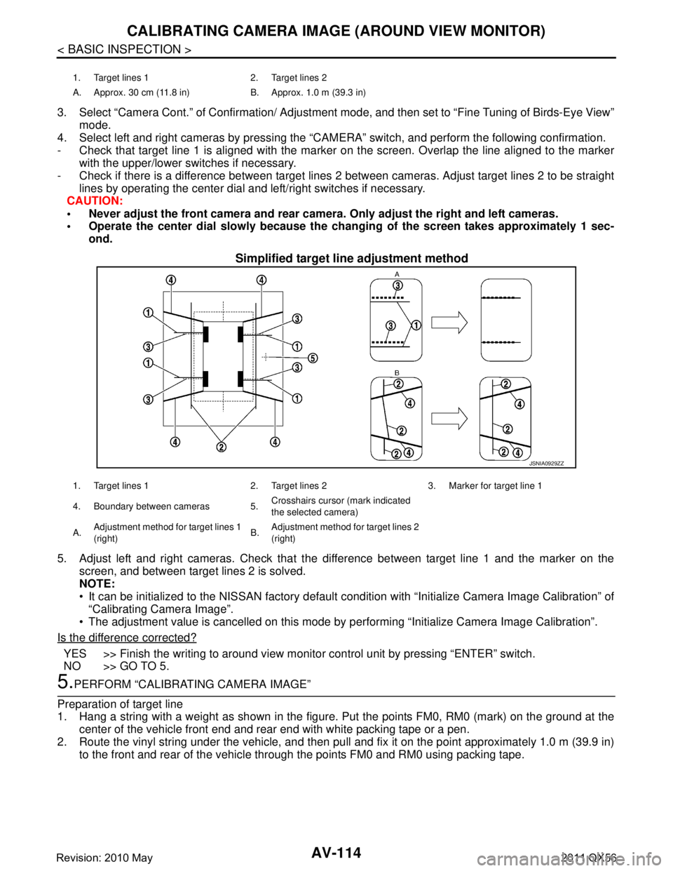
3. Select “Camera Cont.” of Confirmation/ Adjustment mode, and then set to “Fine Tuning of Birds-Eye View”
mode.
4. Select left and right cameras by pressing the “CAM ERA” switch, and perform the following confirmation.
- Check that target line 1 is aligned with the marker on the screen. Overlap the line aligned to the marker
with the upper/lower switches if necessary.
- Check if there is a difference between target lines 2 between cameras. Adjust target lines 2 to be straight
lines by operating the center dial and left/right switches if necessary.
CAUTION:
Never adjust the front camera and rear camer a. Only adjust the right and left cameras.
Operate the center dial slowly because the ch anging of the screen takes approximately 1 sec-
ond.
Simplified target line adjustment method
5. Adjust left and right cameras. Check that the difference between target line 1 and the marker on the
screen, and between target lines 2 is solved.
NOTE:
It can be initialized to the NISSAN factory default c ondition with “Initialize Camera Image Calibration” of
“Calibrating Camera Image”.
The adjustment value is cancelled on this mode by performing “Initialize Camera Image Calibration”.
Is the difference corrected?
YES >> Finish the writing to around view monito r control unit by pressing “ENTER” switch.
NO >> GO TO 5.
5.PERFORM “CALIBRATING CAMERA IMAGE”
Preparation of target line
1. Hang a string with a weight as shown in the figure. Put the points FM0, RM0 (mark) on the ground at the
center of the vehicle front end and rear end with white packing tape or a pen.
2. Route the vinyl string under the vehicle, and then pull and fix it on the point approximately 1.0 m (39.9 in)
to the front and rear of the vehicle through the points FM0 and RM0 using packing tape.
1. Target lines 1 2. Target lines 2
A. Approx. 30 cm (11.8 in) B. Approx. 1.0 m (39.3 in)
JSNIA0929ZZ
1. Target lines 1 2. Target lines 2 3. Marker for target line 1
4. Boundary between cameras 5. Crosshairs cursor (mark indicated
the selected camera)
A. Adjustment method for target lines 1
(right) B.
Adjustment method for target lines 2
(right)
Revision: 2010 May2011 QX56
Page 263 of 5598
AV
CALIBRATING CAMERA IMAGE (AROUND VIEW MONITOR)
AV-115
< BASIC INSPECTION >
C
D E
F
G H
I
J
K L
M B A
O P
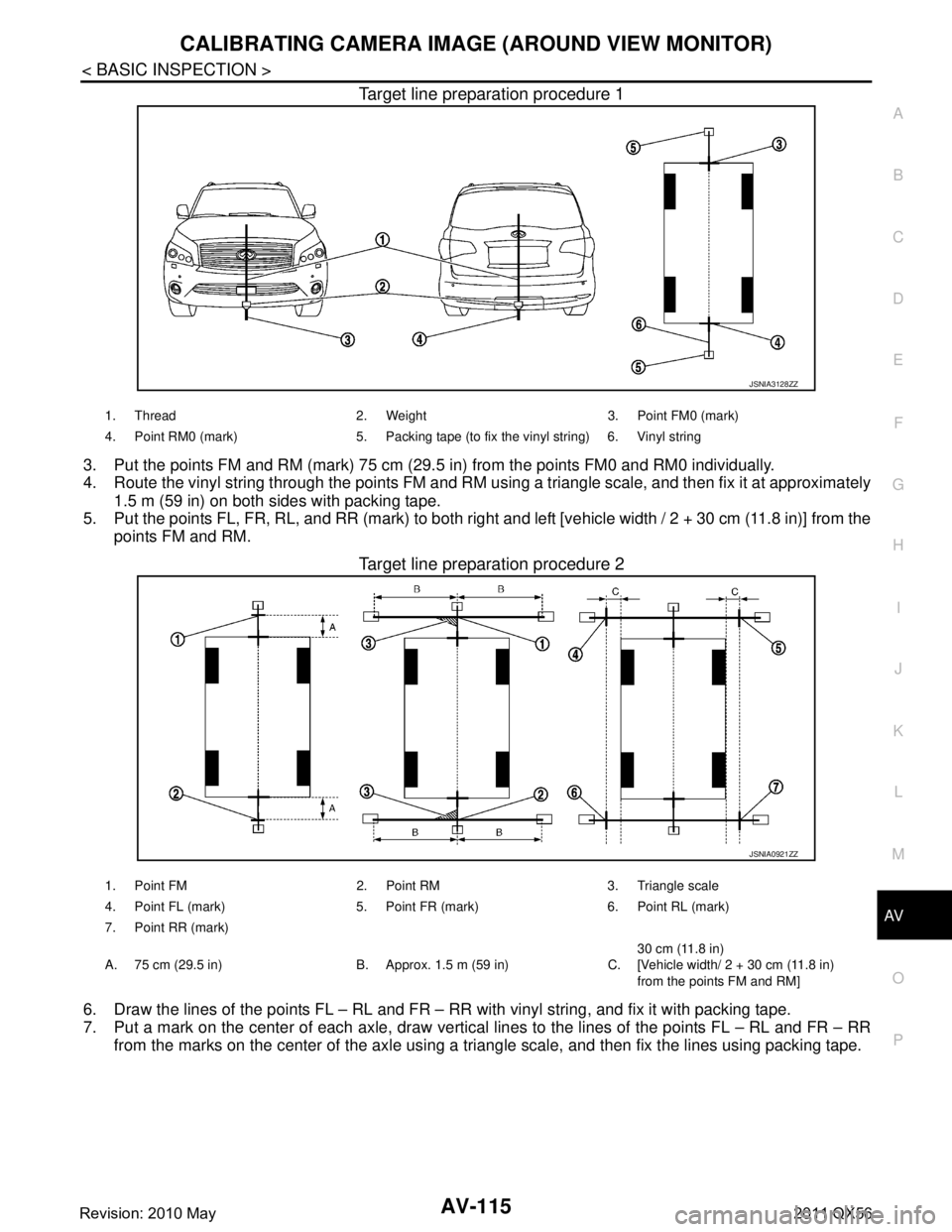
Target line preparation procedure 1
3. Put the points FM and RM (mark) 75 cm (29.5 in) from the points FM0 and RM0 individually.
4. Route the vinyl string through the points FM and RM us ing a triangle scale, and then fix it at approximately
1.5 m (59 in) on both sides with packing tape.
5. Put the points FL, FR, RL, and RR (mark) to both right and left [vehicle width / 2 + 30 cm (11.8 in)] from the
points FM and RM.
Target line preparation procedure 2
6. Draw the lines of the points FL – RL and FR – RR with vinyl string, and fix it with packing tape.
7. Put a mark on the center of each axle, draw vertical lines to the lines of the points FL – RL and FR – RR
from the marks on the center of t he axle using a triangle scale, and then fix the lines using packing tape.
JSNIA3128ZZ
1. Thread 2. Weight 3. Point FM0 (mark)
4. Point RM0 (mark) 5. Packing tape (to fix the vinyl string) 6. Vinyl string
JSNIA0921ZZ
1. Point FM 2. Point RM 3. Triangle scale
4. Point FL (mark) 5. Point FR (mark) 6. Point RL (mark)
7. Point RR (mark)
A. 75 cm (29.5 in) B. Approx. 1.5 m (59 in) C. 30 cm (11.8 in)
[Vehicle width/ 2 + 30 cm (11.8 in)
from the points FM and RM]
Revision: 2010 May2011 QX56
Page 532 of 5598
![INFINITI QX56 2011 Factory Service Manual
COMPONENT PARTSBRC-15
< SYSTEM DESCRIPTION > [WITH VDC]
C
D
E
G H
I
J
K L
M A
B
BRC
N
O P
Downsize and weight reduction is aimed. IC for detection portion and magnet for sensor rotor are adopted.
INFINITI QX56 2011 Factory Service Manual
COMPONENT PARTSBRC-15
< SYSTEM DESCRIPTION > [WITH VDC]
C
D
E
G H
I
J
K L
M A
B
BRC
N
O P
Downsize and weight reduction is aimed. IC for detection portion and magnet for sensor rotor are adopted.
](/img/42/57033/w960_57033-531.png)
COMPONENT PARTSBRC-15
< SYSTEM DESCRIPTION > [WITH VDC]
C
D
E
G H
I
J
K L
M A
B
BRC
N
O P
Downsize and weight reduction is aimed. IC for detection portion and magnet for sensor rotor are adopted.
Power supply is supplied to detection portion so that magnetic field
line is read. Magnetic field that is detected is converted to current
signal.
When sensor rotor rotates, magnetic field changes. Magnetic field
change is converted to current signals (rectangular wave) and is
transmitted to ABS actuator and electric unit (control unit). Change
of magnetic field is pr oportional to wheel speed.
Stop Lamp SwitchINFOID:0000000006222563
Detects the operation status of brake pedal and transmits converted electric signal to ABS actuator and elec-
tric unit (control unit).
Steering Angle SensorINFOID:0000000006222564
Detects the following information and transmits steering angle signal to ABS actuator and electric unit (control
unit) via CAN communication.
Steering wheel rotation amount
Steering wheel rotation angular velocity
Steering wheel rotation direction
Yaw Rate/Side/Decel G sensorINFOID:0000000006222565
Calculates the following information that affects the v ehicle and transmits a signal to ABS actuator and electric
unit (control unit) via communication lines.
Vehicle rotation angular velocity (yaw rate signal)
Vehicle lateral acceleration (side G signal) / longitudinal acceleration (decel G signal)
Brake Fluid Level SwitchINFOID:0000000006222566
Detects the brake fluid level in reservoir tank and trans mits converted electric signal from ABS actuator and
electric unit (control unit), when brake fluid level is the specified level or less.
Parking Brake SwitchINFOID:0000000006222567
Detects the operation status of parking brake switch and transmits converted electric signal from combination
meter to ABS actuator and electric unit (control unit).
VDC OFF SwitchINFOID:0000000006222568
VDC OFF switch is integrated in SNOW MODE / TOW MODE / VDC OFF switch assembly (2WD models) or
4WD switch assembly (4WD models).
The operation of the VDC OFF switch enables the arbi trary switching of the VDC function between stop sta-
tus and standby status. The status of the function is indicated by the VDC OFF indicator lamp. (ON: Non-
operational status, OFF: Standby status)
- VDC function NOTE:
Brake limited slip differentia l (BLSD) control operates.
- TCS function
VDC OFF indicator lamp turns OFF (standby status) when the engine is started again after it is stopped once while VDC OFF indicator lamp is ON (non-operational status).
JPFIC0131GB
Revision: 2010 May2011 QX56
Page 552 of 5598
![INFINITI QX56 2011 Factory Service Manual
SYSTEMBRC-35
< SYSTEM DESCRIPTION > [WITH VDC]
C
D
E
G H
I
J
K L
M A
B
BRC
N
O P
EBD function is expanded and developed from conventi onal ABS function and corrects rear wheel brake
force to approp INFINITI QX56 2011 Factory Service Manual
SYSTEMBRC-35
< SYSTEM DESCRIPTION > [WITH VDC]
C
D
E
G H
I
J
K L
M A
B
BRC
N
O P
EBD function is expanded and developed from conventi onal ABS function and corrects rear wheel brake
force to approp](/img/42/57033/w960_57033-551.png)
SYSTEMBRC-35
< SYSTEM DESCRIPTION > [WITH VDC]
C
D
E
G H
I
J
K L
M A
B
BRC
N
O P
EBD function is expanded and developed from conventi onal ABS function and corrects rear wheel brake
force to appropriate level by electronic control according to load weight (number of passengers).
During braking, control unit portion compares slight slip on front and rear wheels by wheel speed sensor signal, transmits drive sig-
nal to actuator portion when rear wheel slip exceeds front wheel
slip for the specified value or more, and controls rear wheel brake
force (brake fluid pressure) so t hat increase of rear wheel slip is
prevented and slips on front wheel and rear wheel are nearly
equalized. ABS control is applied when slip on each wheel
increases and wheel speed is the threshold value of ABS control or
less.
CONSULT-III can be used to diagnose the system diagnosis.
Fail-safe function is adopted. When a malfunction occurs in EBD function, the control is suspended for VDC function, TCS function,
ABS function, EBD function, hill start assist function and brake lim-
ited slip differential (BLSD) func tion. The vehicle status becomes
the same as models without VDC function, TCS function, ABS
function, EBD function, hill start assist function and brake limited
slip differential (BLSD) function. Refer to BRC-25, "
Fail-safe".
JPFIC0142GB
JPFIC0143GB
Revision: 2010 May2011 QX56
Page 679 of 5598

BRM-4
< PRECAUTION >
REPAIRING HIGH STRENGTH STEEL
PRECAUTION
REPAIRING HIGH STRENGTH STEEL
High Strength Steel (HSS)INFOID:0000000006248484
High strength steel is used for body panels in order to reduce vehicle weight.
Accordingly, precautions in repairing automotive bodies made of high strength steel are described below:
Read the following precautions when repairing HSS:
1. Additional points to consider
Tensile strength Major applicable parts 440 - 780 MPa Rear floor reinforcement
2nd seat mounting member assembly
Front seat mounting rear crossmember assembly
Front floor reinforcement
2nd crossmember (Lower)
Side radiator core support
Radiator core support main assembly
Front side member assembly
4th crossmember
2nd seat mounting crossmember
Rear side member
Rear crossmember
Inner side roof rail
Upper inner front pillar
Inner center pillar
Upper front pillar reinforcement
Lower center pillar brace
Front pillar brace
Outer sill reinforcement
Front roof rail
Rear roof rail
Radiator guard crossmember assembly
2nd crossmember assembly
2nd crossmember reinforcement
Front side member assembly
Front bound bumper bracket assembly
Lower front link mounting bracket assembly
Center side member assembly
Fuel tank protector assembly
Rear suspension mounting bracket assembly
Rear shock absorber bracket assembly
Rear side member assembly
Rear end gusset
Rear end crossmember assembly
980 - 1350 MPa Lower dash center reinforcement
(Lower dash Component part)
Inner sill
Rear seat crossmember
(2nd seat mounting crossmember component part)
Inner center pillar (Upper)
Upper outer center pillar reinforcement
(Lower center pillar brace component part)
Front bumper crossmember assembly
Revision: 2010 May2011 QX56
Page 809 of 5598
![INFINITI QX56 2011 Factory Service Manual
CCS-74
< BASIC INSPECTION >[ICC]
LASER BEAM AIMING ADJUSTMENT
Suspend a weight from a string (1) at
tached to its end at the point (B)
leftward from the ICC target board center (A).
>> GO TO 3.
3.SE INFINITI QX56 2011 Factory Service Manual
CCS-74
< BASIC INSPECTION >[ICC]
LASER BEAM AIMING ADJUSTMENT
Suspend a weight from a string (1) at
tached to its end at the point (B)
leftward from the ICC target board center (A).
>> GO TO 3.
3.SE](/img/42/57033/w960_57033-808.png)
CCS-74
< BASIC INSPECTION >[ICC]
LASER BEAM AIMING ADJUSTMENT
Suspend a weight from a string (1) at
tached to its end at the point (B)
leftward from the ICC target board center (A).
>> GO TO 3.
3.SETTING ICC TARGET BOARD
1. Suspend a thread with weight on tip from the center of the front and rear bumpers. Then, mark the center
points on the ground as each weight point.
2. Link the front and rear bumpers center point s marked on the ground and extend a straight line ahead.
Then mark a point 3.9 m (12.8 ft) position ahead of t he front bumper. Then, adjust the position of the ICC
target board so that the weight comes on the top of the marked point [3.9 m (12.8 ft) position ahead of the
front bumper] and face to the vehicle.
3. Remove the thread suspended to the left side of I CC target board and suspend a thread with weight on tip
on the center of the ICC ta rget board. Then mark the poi nt of weight on the ground.
4. Pivot the edge of the ICC target board 25 ° (a) to either side.
NOTE:
Approx. 90 mm (3.54 in) (b) shift rates the 25 ° (a) movement.
>> GO TO 4.
4.CHECK THE ICC TARGET BOA RD INSTALLATION POSITION
Check that the ICC target board (1) is located as shown in the figure.
NOTE:
The distance between laser beam axis and I CC target board is 4.0 m (13.0 ft).
>> GO TO 5.
W [mm (in)] : 34 (1.34)
JSOIA0337ZZ
1 : ICC target board
2 : String with a weight
C : ICC target board center marking point
JSOIA0026ZZ
1. ICC target board 2. ICC sensor 3. Vehicle
B. Vehicle center L
1. 4.0 m (13.0 ft)
W. 34 mm (1.34 in)
a. 25 °
JSOIA0338ZZ
Revision: 2010 May2011 QX56
Page 1751 of 5598
HOOD
DLK-215
< REMOVAL AND INSTALLATION >
C
D E
F
G H
I
J
L
M A
B
DLK
N
O P
REMOVAL AND INSTALLATION
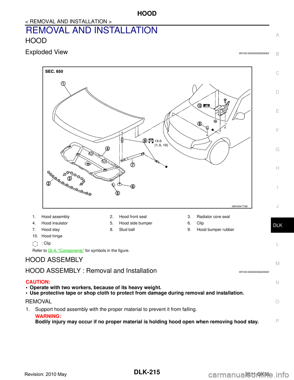
HOOD
Exploded ViewINFOID:0000000006226062
HOOD ASSEMBLY
HOOD ASSEMBLY : Removal and InstallationINFOID:0000000006226063
CAUTION:
Operate with two workers, because of its heavy weight.
Use protective tape or shop cloth to protect from damage during removal and installation.
REMOVAL
1. Support hood assembly with the proper material to prevent it from falling.
WARNING:
Bodily injury may occur if no proper material is holding hood open when removing hood stay.
1. Hood assembly 2. Hood front seal 3. Radiator core seal
4. Hood insulator 5. Hood side bumper 6. Clip
7. Hood stay 8. Stud ball 9. Hood bumper rubber
10. Hood hinge
: Clip
Refer to GI-4, "
Components" for symbols in the figure.
JMKIA5477GB
Revision: 2010 May2011 QX56
Page 1753 of 5598
HOOD
DLK-217
< REMOVAL AND INSTALLATION >
C
D E
F
G H
I
J
L
M A
B
DLK
N
O P
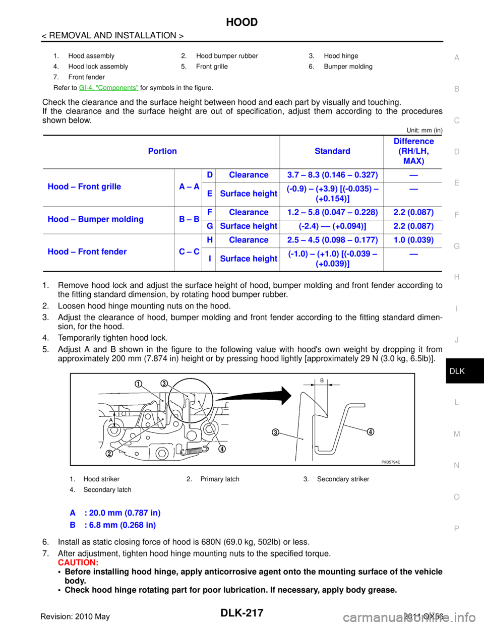
Check the clearance and the surface height betw een hood and each part by visually and touching.
If the clearance and the surface height are out of spec ification, adjust them according to the procedures
shown below.
Unit: mm (in)
1. Remove hood lock and adjust the surface height of hood, bumper molding and front fender according to
the fitting standard dimension, by rotating hood bumper rubber.
2. Loosen hood hinge mounting nuts on the hood.
3. Adjust the clearance of hood, bumper molding and fr ont fender according to the fitting standard dimen-
sion, for the hood.
4. Temporarily tighten hood lock.
5. Adjust A and B shown in the figure to the following value with hood's own weight by dropping it from approximately 200 mm (7.874 in) height or by pressi ng hood lightly [approximately 29 N (3.0 kg, 6.5lb)].
6. Install as static closing force of hood is 680N (69.0 kg, 502lb) or less.
7. After adjustment, tighten hood hinge mounting nuts to the specified torque. CAUTION:
Before installing hood hinge, apply anticorrosive agent onto th e mounting surface of the vehicle
body.
Check hood hinge rotating pa rt for poor lubrication. If necessary, apply body grease.
1. Hood assembly 2. Hood bumper rubber 3. Hood hinge
4. Hood lock assembly 5. Front grille 6. Bumper molding
7. Front fender
Refer to GI-4, "
Components" for symbols in the figure.
Portion Standard Difference
(RH/LH, MAX)
Hood – Front grille A – A D Clearance 3.7 – 8.3 (0.146 – 0.327) —
E Surface height (-0.9) – (+3.9) [(-0.035) –
(+0.154)] —
Hood – Bumper molding B – B F Clearance 1.2 – 5.8 (0.047 – 0.228) 2.2 (0.087)
G Surface height (-2.4) –– (+0.094)] 2.2 (0.087)
Hood – Front fender C – C H Clearance 2.5 – 4.5 (0.098 – 0.177) 1.0 (0.039)
I Surface height (-1.0) – (+1.0) [(-0.039 –
(+0.039)] —
1. Hood striker 2. Primary latch 3. Secondary striker
4. Secondary latch
A : 20.0 mm (0.787 in)
B : 6.8 mm (0.268 in)
PIIB5794E
Revision: 2010 May2011 QX56
Page 1760 of 5598
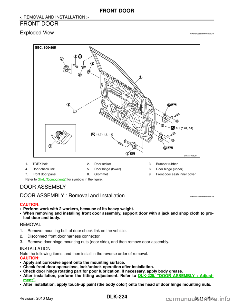
DLK-224
< REMOVAL AND INSTALLATION >
FRONT DOOR
FRONT DOOR
Exploded ViewINFOID:0000000006226074
DOOR ASSEMBLY
DOOR ASSEMBLY : Removal and InstallationINFOID:0000000006226075
CAUTION:
Perform work with 2 workers, because of its heavy weight.
When removing and installing front door assembly, support door with a jack and shop cloth to pro-
tect door and body.
REMOVAL
1. Remove mounting bolt of door check link on the vehicle.
2. Disconnect front door harness connector.
3. Remove door hinge mounting nuts (door side), and then remove door assembly.
INSTALLATION
Note the following items, and then install in the reverse order of removal.
CAUTION:
Apply anticorrosive agent onto the mounting surface.
Check front door open/close, lock/un lock operation after installation.
Check door hinge rotating pa rt for poor lubrication. If necessary, apply body grease.
After installation, perform th e fitting adjustment. Refer to DLK-225, "
DOOR ASSEMBLY : Adjust-
ment".
After installation, apply touch-up paint (the body color) onto the head of door hinge mounting nuts.
1. TORX bolt 2. Door striker 3. Bumper rubber
4. Door check link 5. Door hinge (lower) 6. Door hinge (upper)
7. Front door panel 8. Grommet 9. Front door sash inner cover
Refer to GI-4, "
Components" for symbols in the figure.
JMKIA5363GB
Revision: 2010 May2011 QX56
Page 1762 of 5598

DLK-226
< REMOVAL AND INSTALLATION >
FRONT DOOR
4. Temporarily tighten door hinge mounting nuts on door side.
5. Loosen door hinge mounting bolts on body side.
6. Raise front door at rear end to adjust clearance of the front door according to the fitting standard dimen-
sion.
7. After adjustment tighten bolts and nuts to the specified torque. CAUTION:
After installation, apply touch-up paint (the bo dy color) onto the head of hinge mounting bolts
and nuts.
Check door hinge rotating part for poor lubrication. If necessary, apply body grease.
8. Install front fender. Refer to refer to DLK-222, "
FRONT FENDER : Removal and Installation".
DOOR STRIKER ADJUSTMENT
Adjust door striker so that it becomes parallel with door lock insertion direction.
DOOR STRIKER
DOOR STRIKER : Removal and InstallationINFOID:0000000006226077
REMOVAL
Remove TORX bolts, and then remove door striker.
INSTALLATION
Note the following items, and then install in the reverse order of removal.
CAUTION:
Check front door open/close, operation after installation.
After installation, be sure to perf orm the fitting adjustment. Refer to DLK-225, "
DOOR ASSEMBLY :
Adjustment".
DOOR HINGE
DOOR HINGE : Removal and InstallationINFOID:0000000006226078
REMOVAL
CAUTION:
Perform work with 2 workers, because of its heavy weight.
When removing and installing front door assembly, support door with a jack and shop cloth to pro-
tect door and body.
1. Remove front fender. Refer to DLK-222, "
FRONT FENDER : Removal and Installation".
2. Remove front door assembly. Refer to DLK-224, "
DOOR ASSEMBLY : Removal and Installation".
3. Remove front door hinge mounting bolts (body side), and then remove front door hinge.
INSTALLATION
Note the following items, and then install in the reverse order of removal.
CAUTION:
Apply anticorrosive agent onto the mounting surface.
Check front door open/close, lock/un lock operation after installation.
Check door hinge rotating pa rt for poor lubrication. If necessary, apply body grease.
After installation, perform th e fitting adjustment. Refer to DLK-225, "
DOOR ASSEMBLY : Adjust-
ment".
After installation, apply touch-up paint (the body color) onto the head of door hinge mounting nuts.
DOOR CHECK LINK
DOOR CHECK LINK : Re moval and InstallationINFOID:0000000006226079
REMOVAL
1. Fully close the front door window.
2. Remove front door finisher. Refer to INT-14, "
Removal and Installation".
3. Remove front door speaker mounting bolts.
4. Disconnect connector and remove front door speaker.
Revision: 2010 May2011 QX56