lock INFINITI QX56 2011 Factory Owners Manual
[x] Cancel search | Manufacturer: INFINITI, Model Year: 2011, Model line: QX56, Model: INFINITI QX56 2011Pages: 5598, PDF Size: 94.53 MB
Page 951 of 5598
ENGINE COOLANTCO-9
< PERIODIC MAINTENANCE >
C
DE
F
G H
I
J
K L
M A
CO
NP
O
3. Check drained engine coolant for contaminants such as rust, corrosion or discoloration.
If contaminated, flush the engine cooling system. Refer to CO-10, "
Flushing".
RefillingINFOID:0000000006289659
1. Install reservoir tank if removed, and radiator drain plug.
CAUTION:
Be sure to clean drain plug and install with new O-ring. Refer to CO-13, "
Exploded View".
If water drain plug on cylinder block is removed, close and tighten it. Refer to EM-107, "
Disassem-
bly and Assembly".
2. Check that each hose clamp is firmly tightened.
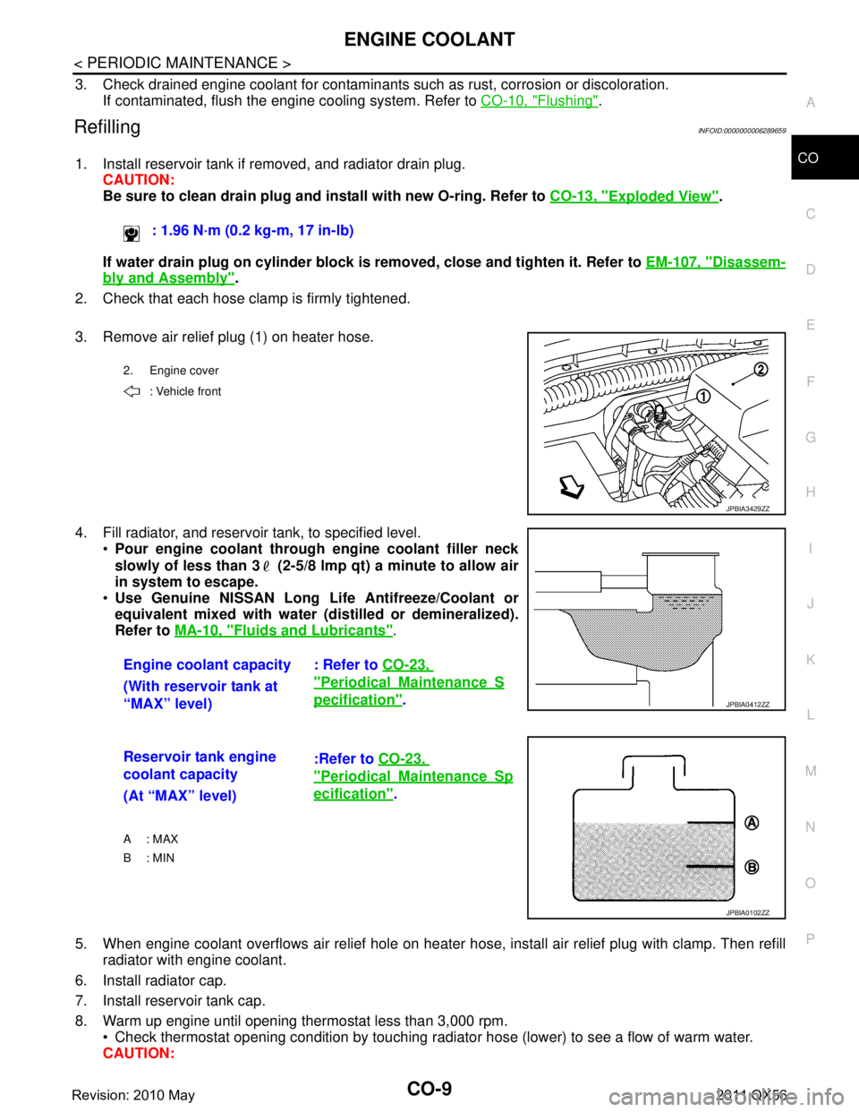
3. Remove air relief plug (1) on heater hose.
4. Fill radiator, and reservoir tank, to specified level. Pour engine coolant through engine coolant filler neck
slowly of less than 3 (2-5/8 lmp qt) a minute to allow air
in system to escape.
Use Genuine NISSAN Long Li fe Antifreeze/Coolant or
equivalent mixed with water (dis tilled or demineralized).
Refer to MA-10, "
Fluids and Lubricants".
5. When engine coolant overflows air relief hole on heater hos e, install air relief plug with clamp. Then refill
radiator with engine coolant.
6. Install radiator cap.
7. Install reservoir tank cap.
8. Warm up engine until opening thermostat less than 3,000 rpm. Check thermostat opening condition by touching radiat or hose (lower) to see a flow of warm water.
CAUTION: : 1.96 N·m (0.2 kg-m, 17 in-lb)
2. Engine cover
: Vehicle front
JPBIA3429ZZ
Engine coolant capacity : Refer to CO-23,
"PeriodicalMaintenanceS
pecification".
(With reservoir tank at
“MAX” level)JPBIA0412ZZ
Reservoir tank engine
coolant capacity :Refer to
CO-23,
"PeriodicalMaintenanceSp
ecification".
(At “MAX” level)
A : MAX
B: MIN
JPBIA0102ZZ
Revision: 2010 May2011 QX56
Page 952 of 5598
CO-10
< PERIODIC MAINTENANCE >
ENGINE COOLANT
Watch water temperature gauge so as not to overheat engine.
9. Stop the engine and cool down to less than approximately 50 °C (122 °F).
Cool down using fan to reduce the time.
If necessary, refill radiator up to filler neck with engine coolant.
10. Refill reservoir tank to “MAX” level line with engine coolant if necessary.
11. Repeat steps 6 through 10 two or more times with reservoir tank cap installed until engine coolant level no longer drops.
12. Check cooling system for leakage with engine running.
13. Warm up the engine, and check for sound of engine coolant flow while running engine from idle up to 3,000 rpm with heater temperature controller set at several position between “COOL” and “WARM”.
Sound may be noticeable at heater unit.
14. Repeat step 13 three times.
15. If sound is heard, bleed air from cooling system by repeating step 4, and steps from 6 to 14 until engine
coolant level no longer drops.
FlushingINFOID:0000000006289660
1. Install reservoir tank if removed, and radiator drain plug. CAUTION:
Be sure to clean drain plug and install with new O-ring. Refer to CO-13, "
Exploded View".
If water drain plug on cylinder block is removed, close and tighten it. Refer to EM-107, "
Disassem-
bly and Assembly".
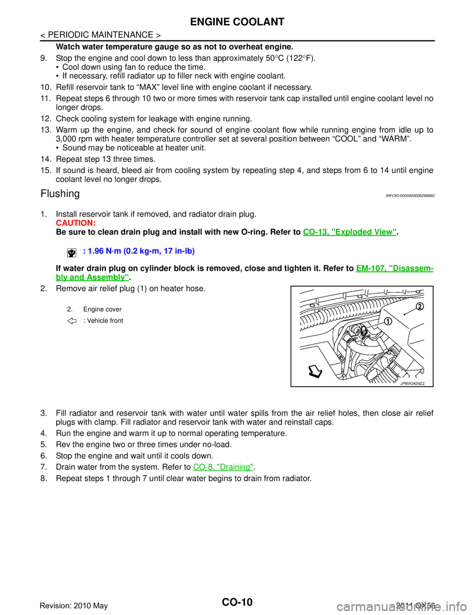
2. Remove air relief plug (1) on heater hose.
3. Fill radiator and reservoir tank with water until water spills from the air relief holes, then close air relief
plugs with clamp. Fill radiator and reservoir tank with water and reinstall caps.
4. Run the engine and warm it up to normal operating temperature.
5. Rev the engine two or three times under no-load.
6. Stop the engine and wait until it cools down.
7. Drain water from the system. Refer to CO-8, "
Draining".
8. Repeat steps 1 through 7 until clear water begins to drain from radiator. : 1.96 N·m (0.2 kg-m, 17 in-lb)
2. Engine cover
: Vehicle front
JPBIA3429ZZ
Revision: 2010 May2011 QX56
Page 960 of 5598
CO-18
< REMOVAL AND INSTALLATION >
WATER PUMP
WATER PUMP
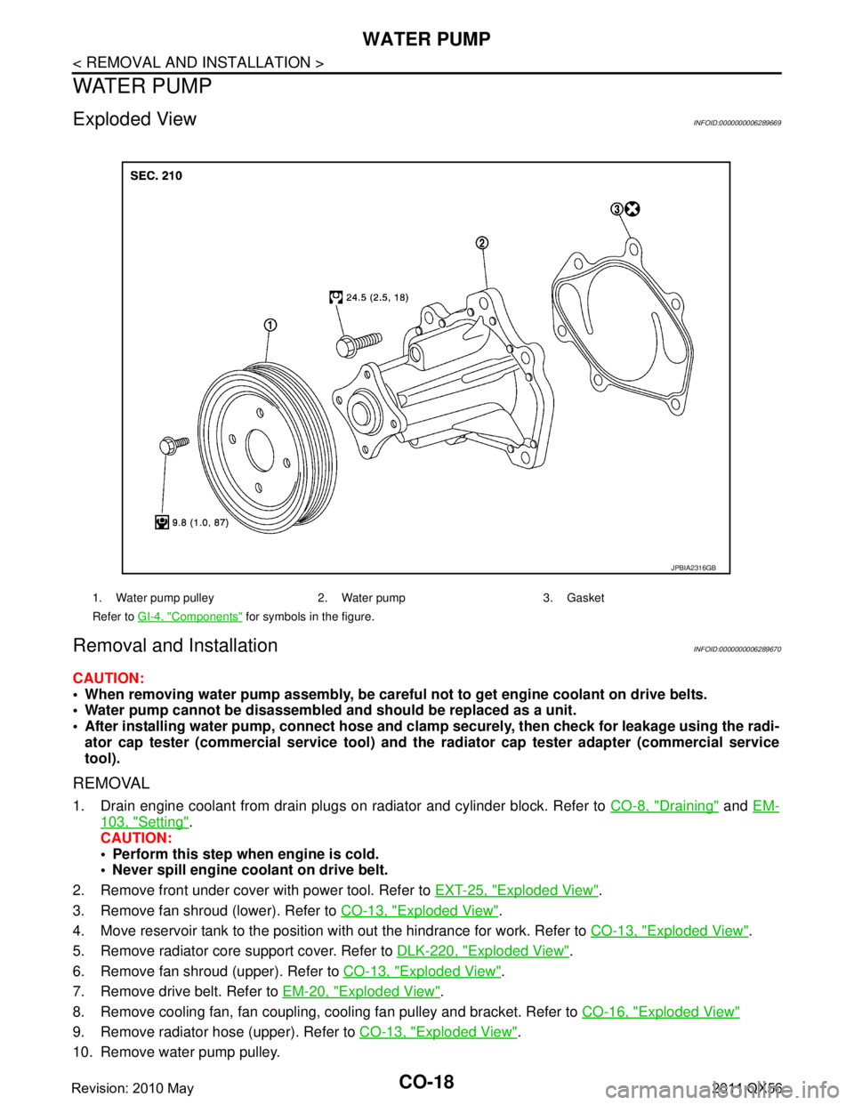
Exploded ViewINFOID:0000000006289669
Removal and InstallationINFOID:0000000006289670
CAUTION:
When removing water pump assembly, be careful not to get engine coolant on drive belts.
Water pump cannot be disassembled and should be replaced as a unit.
After installing water pump, co nnect hose and clamp securely, then check for leakage using the radi-
ator cap tester (commercial service tool) and the radiator cap tester adapter (commercial service
tool).
REMOVAL
1. Drain engine coolant from drain plugs on radiator and cylinder block. Refer to CO-8, "Draining" and EM-
103, "Setting".
CAUTION:
Perform this step when engine is cold.
Never spill engine coolant on drive belt.
2. Remove front under cover with power tool. Refer to EXT-25, "
Exploded View".
3. Remove fan shroud (lower). Refer to CO-13, "
Exploded View".
4. Move reservoir tank to the position with out the hindrance for work. Refer to CO-13, "
Exploded View".
5. Remove radiator core support cover. Refer to DLK-220, "
Exploded View".
6. Remove fan shroud (upper). Refer to CO-13, "
Exploded View".
7. Remove drive belt. Refer to EM-20, "
Exploded View".
8. Remove cooling fan, fan coupling, cooling fan pulley and bracket. Refer to CO-16, "
Exploded View"
9. Remove radiator hose (upper). Refer to CO-13, "Exploded View".
10. Remove water pump pulley.
1. Water pump pulley 2. Water pump 3. Gasket
Refer to GI-4, "
Components" for symbols in the figure.
JPBIA2316GB
Revision: 2010 May2011 QX56
Page 961 of 5598
WATER PUMPCO-19
< REMOVAL AND INSTALLATION >
C
DE
F
G H
I
J
K L
M A
CO
NP
O
11. Remove water pump. Refer to
CO-18, "Exploded View".
Engine coolant will leak from cylinder block, so have a receptacle ready under vehicle.
CAUTION:
Handle the water pump vane so that it does not contact any other parts.
Never disassemble water pump.
INSTALLATION
Install in the reverse order of removal.
InspectionINFOID:0000000006289671
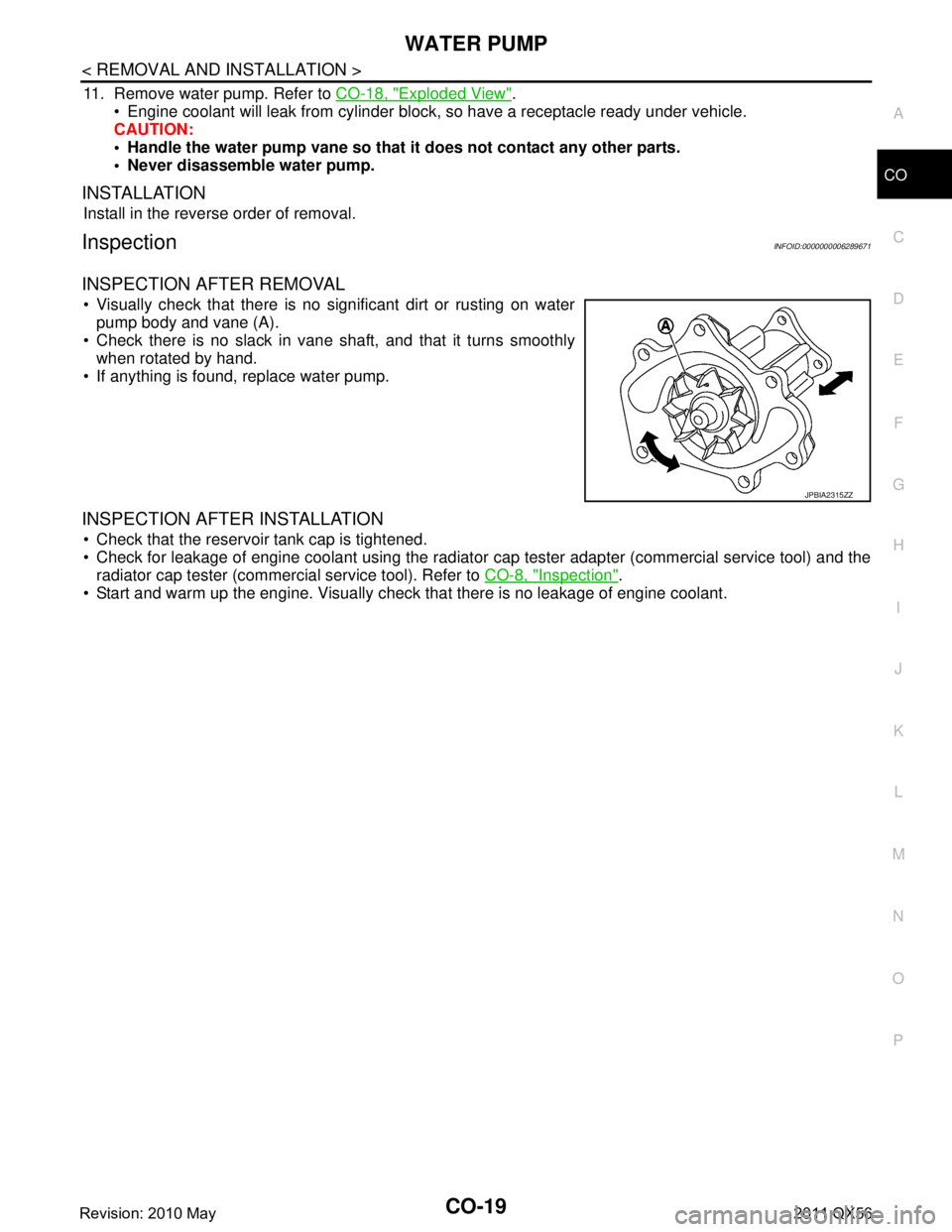
INSPECTION AFTER REMOVAL
Visually check that there is no significant dirt or rusting on water pump body and vane (A).
Check there is no slack in vane shaft, and that it turns smoothly when rotated by hand.
If anything is found, replace water pump.
INSPECTION AFTER INSTALLATION
Check that the reservoir tank cap is tightened.
Check for leakage of engine coolant using the radiator cap tester adapter (commercial service tool) and the
radiator cap tester (commercial service tool). Refer to CO-8, "
Inspection".
Start and warm up the engine. Visually check that there is no leakage of engine coolant.
JPBIA2315ZZ
Revision: 2010 May2011 QX56
Page 963 of 5598
WATER INLET AND THERMOSTAT ASSEMBLYCO-21
< REMOVAL AND INSTALLATION >
C
DE
F
G H
I
J
K L
M A
CO
NP
O
2. Remove front under cover with power tool. Refer to
EXT-25, "Exploded View".
3. Drain engine coolant from drain plugs on radiator and cylinder block. Refer to CO-8, "
Draining" and EM-
103, "Setting".
CAUTION:
Perform this step when engine is cold.
Never spill engine coolant on drive belts.
4. Disconnect radiator hose (upper and lower). Refer to CO-13, "
Exploded View".
5. Remove intake manifold. Refer to EM-30, "
Exploded View".
6. Remove fuel feed tube. Refer to EM-43, "
Exploded View".
7. Remove water hose, water connector, heater pipes and heater hoses.
8. Remove thermostat housing.
9. Remove water inlet and thermostat.
INSTALLATION
Note the following, and install in the reverse order of removal.
CAUTION:
Be careful not to spill engine coolant over en gine room. Use rag to absorb engine coolant.
Thermostat
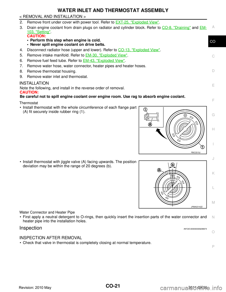
Install thermostat with the whole circumference of each flange part
(A) fit securely inside rubber ring (1).
Install thermostat with jiggle valve (A) facing upwards. The position deviation may be within the range of 20 degrees (b).
Water Connector and Heater Pipe
First apply a neutral detergent to O-rings, then quickly in sert the insertion parts of the water connector and
heater pipe into the installation holes.
InspectionINFOID:0000000006289674
INSPECTION AFTER REMOVAL
Check that valve in thermostat is co mpletely closing at normal temperature.
PBIC3315J
JPBIA2314ZZ
Revision: 2010 May2011 QX56
Page 974 of 5598

DAS-9
C
DE
F
G H
I
J
K L
M B
DAS
N
P A
DTC Index ...........................................................
..
445
SIDE RADAR RH .............................................446
Reference Value ................................................. ..446
Fail-safe ................................................................446
DTC Inspection Priority Chart ...............................447
DTC Index .............................................................447
WIRING DIAGRAM ....................................448
DRIVER ASSISTANCE SYSTEMS ................ ..448
Wiring Diagram ................................................... ..448
BASIC INSPECTION .................................463
DIAGNOSIS AND REPAIR WORK FLOW .... ..463
Work Flow ........................................................... ..463
PRE-INSPECTION FOR DIAGNOSIS ..............466
Inspection Procedure .......................................... ..466
ADDITIONAL SERVICE WHEN REPLACING
SIDE RADAR .................................................. ..
467
Description .......................................................... ..467
Work Procedure ....................................................467
ACTION TEST ..................................................468
Description .......................................................... ..468
Work Procedure ....................................................468
DTC/CIRCUIT DIAGNOSIS .......................470
C1A00 CONTROL UNIT ................................. ..470
DTC Logic ........................................................... ..470
Diagnosis Procedure .............................................470
C1A01 POWER SUPPLY CIRCUIT 1, C1A02
POWER SUPPLY CIRCUIT 2 ..........................
471
DTC Logic ........................................................... ..471
Diagnosis Procedure .............................................471
C1A03 VEHICLE SPEED SENSOR .................472
DTC Logic ........................................................... ..472
Diagnosis Procedure .............................................472
C1A15 GEAR POSITION .................................473
Description .......................................................... ..473
DTC Logic .............................................................473
Diagnosis Procedure .............................................473
C1A24 NP RANGE ...........................................475
DTC Logic ........................................................... ..475
Diagnosis Procedure .............................................475
C1A39 STEERING ANGLE SENSOR ..............477
DTC Logic ........................................................... ..477
Diagnosis Procedure .............................................477
C1B50 SIDE RADAR MALFUNCTION ............478
DTC LOGIC ......................................................... ..478
Diagnosis Procedure .............................................478
C1B51 BSW/BSI INDICATOR SHORT CIR-
CUIT ................................................................
479
DTC Logic ............................................................ ..479
Diagnosis Procedure .............................................479
C1B52 BSW/BSI INDICATOR OPEN CIR-
CUIT ................................................................
480
DTC Logic ..............................................................480
Diagnosis Procedure .............................................480
C1B53 SIDE RADAR RIGHT MALFUNCTION .482
DTC Logic ............................................................ ..482
Diagnosis Procedure .............................................482
C1B54 SIDE RADAR LEFT MALFUNCTION .483
DTC Logic ..............................................................483
Diagnosis Procedure .............................................483
C1B55 RADAR BLOCKAGE ..........................484
DTC Logic ..............................................................484
Diagnosis Procedure .............................................484
U1000 CAN COMM CIRCUIT .........................485
SIDE RADAR LH ................................................... ..485
SIDE RADAR LH : Description ..............................485
SIDE RADAR LH : DTC Logic ...............................485
SIDE RADAR LH : Diagnosis Procedure ...............485
SIDE RADAR RH ................................................... ..485
SIDE RADAR RH : Description .............................485
SIDE RADAR RH : DTC Logic ..............................486
SIDE RADAR RH : Diagnosis Procedure ..............486
ADAS CONTROL UNIT ......................................... ..486
ADAS CONTROL UNIT : Description ....................486
ADAS CONTROL UNIT : DTC Logic .....................486
ADAS CONTROL UNIT : Diagnosis Procedure ....486
U1010 CONTROL UNIT (CAN) .......................488
SIDE RADAR LH ................................................... ..488
SIDE RADAR LH : Description ..............................488
SIDE RADAR LH : DTC Logic ...............................488
SIDE RADAR LH : Diagnosis Procedure ...............488
SIDE RADAR RH ................................................... ..488
SIDE RADAR RH : Description .............................488
SIDE RADAR RH : DTC Logic ..............................488
SIDE RADAR RH : Diagnosis Procedure ..............488
ADAS CONTROL UNIT ......................................... ..488
ADAS CONTROL UNIT : Description ....................488
ADAS CONTROL UNIT : DTC Logic .....................489
ADAS CONTROL UNIT : Diagnosis Procedure ....489
U0104 ADAS CAN 1 .......................................490
DTC Logic ............................................................ ..490
Diagnosis Procedure .............................................490
U0121 VDC CAN 2 ..........................................491
DTC Logic ............................................................ ..491
Revision: 2010 May2011 QX56
Page 988 of 5598
![INFINITI QX56 2011 Factory Owners Manual
DAS
DIAGNOSIS SYSTEM (ADAS CONTROL UNIT)
DAS-23
< SYSTEM DESCRIPTION > [ADAS CONTROL UNIT]
C
D
E
F
G H
I
J
K L
M B
N P A
Display Items for The Cause of Automatic Cancellation 2
SELF DIAGNOSTIC RESULT INFINITI QX56 2011 Factory Owners Manual
DAS
DIAGNOSIS SYSTEM (ADAS CONTROL UNIT)
DAS-23
< SYSTEM DESCRIPTION > [ADAS CONTROL UNIT]
C
D
E
F
G H
I
J
K L
M B
N P A
Display Items for The Cause of Automatic Cancellation 2
SELF DIAGNOSTIC RESULT](/img/42/57033/w960_57033-987.png)
DAS
DIAGNOSIS SYSTEM (ADAS CONTROL UNIT)
DAS-23
< SYSTEM DESCRIPTION > [ADAS CONTROL UNIT]
C
D
E
F
G H
I
J
K L
M B
N P A
Display Items for The Cause of Automatic Cancellation 2
SELF DIAGNOSTIC RESULT
Refer to DAS-38, "DTC Index".
DATA MONITOR
INCHING LOST ×A vehicle ahead is not detected during the following driving when
the vehicle speed is approximately 24 km/h (15 MPH) or less
CAN COMM ERROR ×××ADAS control unit received an abnormal signal with CAN commu-
nication
ABS/TCS/VDC CIRC ×××An abnormal condition occurs in VDC/TCS/ABS system
ECD CIRCUIT ×××An abnormal condition occurs in ECD system
ASCD VHCL SPD DTAC ×Vehicle speed is detached from set vehicle speed
ASCD DOUBLE COMD ×Cancel switch and operation switch are detected simultaneously
APA HI TEMP ×The accelerator pedal actuator integrated motor temperature is
high
ICC SENSOR CAN
COMM ERR ××Communication error between ADAS control unit and the ICC sen-
sor
4WD LOCK MODE ×××Shifting of the 4WD shift switch to 4H or 4L
ABS WARNING LAMP ××ABS warning lamp ON
NO RECORD ××× —
Cause of cancellation Description
OPE VDC/TCS/ABS 1 The activation of VDC, TCS, or ABS during LDP system control
Vehicle dynamics Vehicle behavior exceeds specified value
Steering speed Steering speed was more than the specified value in evasive direction
End by yaw angle Yaw angle was the end of LDP control
Departure yaw large Detected more than the specified value of yaw angle in departure direction
ICC WARNING Target approach warning of ICC system, IBA system or FCW system was activated
CURVATURE Road curve was more than the specified value
Steering angle large Steering angle was more than the specified value
Brake is operated Brake pedal was operated
IGN LOW VOLT Decrease in ADAS control unit IGN voltage
Lateral offset Distance of vehicle and lane was detached in lateral direction more than the specified value
Lane marker lost Lane camera unit lost the trace of lane marker
Lane marker unclear Detected lane marker was unclear
Yaw acceleration Detected yawing speed was more than the specified value
Deceleration large Deceleration in a longitudinal direction was more than the specified value
Accel is operated Accelerator pedal was depressed
Departure steering Steering wheel was steered more than the specified value in departure direction
Evasive steering Steering wheel was steered more than the specified value in the evasive direction
R range Selector lever was operated to R range
Parking brake drift Rear wheels lock was detected
Not operating condition Did not meet the operating condition (vehicle speed, turn signal operation, etc)
SNOW MODE SW SNOW mo de switch was pressed
VDC OFF SW VDC OFF switch was pressed
OPE VDC/ABS 2 The activation of VDC or ABS duri ng a standby time of LDP system control
4WD LOCK MODE Shifting of the 4WD shift switch to 4H or 4L
NO RECORD —
Revision: 2010 May2011 QX56
Page 1046 of 5598
![INFINITI QX56 2011 Factory Owners Manual
DAS
DIAGNOSIS SYSTEM (ADAS CONTROL UNIT)
DAS-81
< SYSTEM DESCRIPTION > [DCA]
C
D
E
F
G H
I
J
K L
M B
N P A
Display Items for The Cause of Automatic Cancellation 2
SELF DIAGNOSTIC RESULT
Refer to DAS INFINITI QX56 2011 Factory Owners Manual
DAS
DIAGNOSIS SYSTEM (ADAS CONTROL UNIT)
DAS-81
< SYSTEM DESCRIPTION > [DCA]
C
D
E
F
G H
I
J
K L
M B
N P A
Display Items for The Cause of Automatic Cancellation 2
SELF DIAGNOSTIC RESULT
Refer to DAS](/img/42/57033/w960_57033-1045.png)
DAS
DIAGNOSIS SYSTEM (ADAS CONTROL UNIT)
DAS-81
< SYSTEM DESCRIPTION > [DCA]
C
D
E
F
G H
I
J
K L
M B
N P A
Display Items for The Cause of Automatic Cancellation 2
SELF DIAGNOSTIC RESULT
Refer to DAS-38, "DTC Index".
DATA MONITOR
INCHING LOST ×A vehicle ahead is not detected during the following driving when
the vehicle speed is approximately 24 km/h (15 MPH) or less
CAN COMM ERROR ×××ADAS control unit received an abnormal signal with CAN commu-
nication
ABS/TCS/VDC CIRC ×××An abnormal condition occurs in VDC/TCS/ABS system
ECD CIRCUIT ×××An abnormal condition occurs in ECD system
ASCD VHCL SPD DTAC ×Vehicle speed is detached from set vehicle speed
ASCD DOUBLE COMD ×Cancel switch and operation switch are detected simultaneously
APA HI TEMP ×The accelerator pedal actuator integrated motor temperature is
high
ICC SENSOR CAN
COMM ERR ××Communication error between ADAS control unit and the ICC sen-
sor
4WD LOCK MODE ×××Shifting of the 4WD shift switch to 4H or 4L
ABS WARNING LAMP ××ABS warning lamp ON
NO RECORD ××× —
Cause of cancellation Description
OPE VDC/TCS/ABS 1 The activation of VDC, TCS, or ABS during LDP system control
Vehicle dynamics Vehicle behavior exceeds specified value
Steering speed Steering speed was more than the specified value in evasive direction
End by yaw angle Yaw angle was the end of LDP control
Departure yaw large Detected more than the specified value of yaw angle in departure direction
ICC WARNING Target approach warning of ICC system, IBA system or FCW system was activated
CURVATURE Road curve was more than the specified value
Steering angle large Steering angle was more than the specified value
Brake is operated Brake pedal was operated
IGN LOW VOLT Decrease in ADAS control unit IGN voltage
Lateral offset Distance of vehicle and lane was detached in lateral direction more than the specified value
Lane marker lost Lane camera unit lost the trace of lane marker
Lane marker unclear Detected lane marker was unclear
Yaw acceleration Detected yawing speed was more than the specified value
Deceleration large Deceleration in a longitudinal direction was more than the specified value
Accel is operated Accelerator pedal was depressed
Departure steering Steering wheel was steered more than the specified value in departure direction
Evasive steering Steering wheel was steered more than the specified value in the evasive direction
R range Selector lever was operated to R range
Parking brake drift Rear wheels lock was detected
Not operating condition Did not meet the operating condition (vehicle speed, turn signal operation, etc)
SNOW MODE SW SNOW mo de switch was pressed
VDC OFF SW VDC OFF switch was pressed
OPE VDC/ABS 2 The activation of VDC or ABS duri ng a standby time of LDP system control
4WD LOCK MODE Shifting of the 4WD shift switch to 4H or 4L
NO RECORD —
Revision: 2010 May2011 QX56
Page 1192 of 5598
![INFINITI QX56 2011 Factory Owners Manual
DAS
DIAGNOSIS SYSTEM (ADAS CONTROL UNIT)
DAS-227
< SYSTEM DESCRIPTION > [FCW]
C
D
E
F
G H
I
J
K L
M B
N P A
Display Items for The Cause of Automatic Cancellation 2
SELF DIAGNOSTIC RESULT
Refer to DA INFINITI QX56 2011 Factory Owners Manual
DAS
DIAGNOSIS SYSTEM (ADAS CONTROL UNIT)
DAS-227
< SYSTEM DESCRIPTION > [FCW]
C
D
E
F
G H
I
J
K L
M B
N P A
Display Items for The Cause of Automatic Cancellation 2
SELF DIAGNOSTIC RESULT
Refer to DA](/img/42/57033/w960_57033-1191.png)
DAS
DIAGNOSIS SYSTEM (ADAS CONTROL UNIT)
DAS-227
< SYSTEM DESCRIPTION > [FCW]
C
D
E
F
G H
I
J
K L
M B
N P A
Display Items for The Cause of Automatic Cancellation 2
SELF DIAGNOSTIC RESULT
Refer to DAS-38, "DTC Index".
DATA MONITOR
INCHING LOST ×A vehicle ahead is not detected during the following driving when
the vehicle speed is approximately 24 km/h (15 MPH) or less
CAN COMM ERROR ×××ADAS control unit received an abnormal signal with CAN commu-
nication
ABS/TCS/VDC CIRC ×××An abnormal condition occurs in VDC/TCS/ABS system
ECD CIRCUIT ×××An abnormal condition occurs in ECD system
ASCD VHCL SPD DTAC ×Vehicle speed is detached from set vehicle speed
ASCD DOUBLE COMD ×Cancel switch and operation switch are detected simultaneously
APA HI TEMP ×The accelerator pedal actuator integrated motor temperature is
high
ICC SENSOR CAN
COMM ERR ××Communication error between ADAS control unit and the ICC sen-
sor
4WD LOCK MODE ×××Shifting of the 4WD shift switch to 4H or 4L
ABS WARNING LAMP ××ABS warning lamp ON
NO RECORD ××× —
Cause of cancellation Description
OPE VDC/TCS/ABS 1 The activation of VDC, TCS, or ABS during LDP system control
Vehicle dynamics Vehicle behavior exceeds specified value
Steering speed Steering speed was more than the specified value in evasive direction
End by yaw angle Yaw angle was the end of LDP control
Departure yaw large Detected more than the specified value of yaw angle in departure direction
ICC WARNING Target approach warning of ICC system, IBA system or FCW system was activated
CURVATURE Road curve was more than the specified value
Steering angle large Steering angle was more than the specified value
Brake is operated Brake pedal was operated
IGN LOW VOLT Decrease in ADAS control unit IGN voltage
Lateral offset Distance of vehicle and lane was detached in lateral direction more than the specified value
Lane marker lost Lane camera unit lost the trace of lane marker
Lane marker unclear Detected lane marker was unclear
Yaw acceleration Detected yawing speed was more than the specified value
Deceleration large Deceleration in a longitudinal direction was more than the specified value
Accel is operated Accelerator pedal was depressed
Departure steering Steering wheel was steered more than the specified value in departure direction
Evasive steering Steering wheel was steered more than the specified value in the evasive direction
R range Selector lever was operated to R range
Parking brake drift Rear wheels lock was detected
Not operating condition Did not meet the operating condition (vehicle speed, turn signal operation, etc)
SNOW MODE SW SNOW mo de switch was pressed
VDC OFF SW VDC OFF switch was pressed
OPE VDC/ABS 2 The activation of VDC or ABS duri ng a standby time of LDP system control
4WD LOCK MODE Shifting of the 4WD shift switch to 4H or 4L
NO RECORD —
Revision: 2010 May2011 QX56
Page 1258 of 5598
![INFINITI QX56 2011 Factory Owners Manual
DAS
DIAGNOSIS SYSTEM (ADAS CONTROL UNIT)
DAS-293
< SYSTEM DESCRIPTION > [LDW & LDP]
C
D
E
F
G H
I
J
K L
M B
N P A
Display Items for The Cause of Automatic Cancellation 2
SELF DIAGNOSTIC RESULT
Refer INFINITI QX56 2011 Factory Owners Manual
DAS
DIAGNOSIS SYSTEM (ADAS CONTROL UNIT)
DAS-293
< SYSTEM DESCRIPTION > [LDW & LDP]
C
D
E
F
G H
I
J
K L
M B
N P A
Display Items for The Cause of Automatic Cancellation 2
SELF DIAGNOSTIC RESULT
Refer](/img/42/57033/w960_57033-1257.png)
DAS
DIAGNOSIS SYSTEM (ADAS CONTROL UNIT)
DAS-293
< SYSTEM DESCRIPTION > [LDW & LDP]
C
D
E
F
G H
I
J
K L
M B
N P A
Display Items for The Cause of Automatic Cancellation 2
SELF DIAGNOSTIC RESULT
Refer to DAS-38, "DTC Index".
DATA MONITOR
INCHING LOST ×A vehicle ahead is not detected during the following driving when
the vehicle speed is approximately 24 km/h (15 MPH) or less
CAN COMM ERROR ×××ADAS control unit received an abnormal signal with CAN commu-
nication
ABS/TCS/VDC CIRC ×××An abnormal condition occurs in VDC/TCS/ABS system
ECD CIRCUIT ×××An abnormal condition occurs in ECD system
ASCD VHCL SPD DTAC ×Vehicle speed is detached from set vehicle speed
ASCD DOUBLE COMD ×Cancel switch and operation switch are detected simultaneously
APA HI TEMP ×The accelerator pedal actuator integrated motor temperature is
high
ICC SENSOR CAN
COMM ERR ××Communication error between ADAS control unit and the ICC sen-
sor
4WD LOCK MODE ×××Shifting of the 4WD shift switch to 4H or 4L
ABS WARNING LAMP ××ABS warning lamp ON
NO RECORD ××× —
Cause of cancellation Description
OPE VDC/TCS/ABS 1 The activation of VDC, TCS, or ABS during LDP system control
Vehicle dynamics Vehicle behavior exceeds specified value
Steering speed Steering speed was more than the specified value in evasive direction
End by yaw angle Yaw angle was the end of LDP control
Departure yaw large Detected more than the specified value of yaw angle in departure direction
ICC WARNING Target approach warning of ICC system, IBA system or FCW system was activated
CURVATURE Road curve was more than the specified value
Steering angle large Steering angle was more than the specified value
Brake is operated Brake pedal was operated
IGN LOW VOLT Decrease in ADAS control unit IGN voltage
Lateral offset Distance of vehicle and lane was detached in lateral direction more than the specified value
Lane marker lost Lane camera unit lost the trace of lane marker
Lane marker unclear Detected lane marker was unclear
Yaw acceleration Detected yawing speed was more than the specified value
Deceleration large Deceleration in a longitudinal direction was more than the specified value
Accel is operated Accelerator pedal was depressed
Departure steering Steering wheel was steered more than the specified value in departure direction
Evasive steering Steering wheel was steered more than the specified value in the evasive direction
R range Selector lever was operated to R range
Parking brake drift Rear wheels lock was detected
Not operating condition Did not meet the operating condition (vehicle speed, turn signal operation, etc)
SNOW MODE SW SNOW mo de switch was pressed
VDC OFF SW VDC OFF switch was pressed
OPE VDC/ABS 2 The activation of VDC or ABS duri ng a standby time of LDP system control
4WD LOCK MODE Shifting of the 4WD shift switch to 4H or 4L
NO RECORD —
Revision: 2010 May2011 QX56