INFINITI QX56 2011 Factory Service Manual
Manufacturer: INFINITI, Model Year: 2011, Model line: QX56, Model: INFINITI QX56 2011Pages: 5598, PDF Size: 94.53 MB
Page 3411 of 5598
INSTRUMENT PANEL ASSEMBLYIP-21
< REMOVAL AND INSTALLATION >
C
DE
F
G H
I
K L
M A
B
IP
N
O P
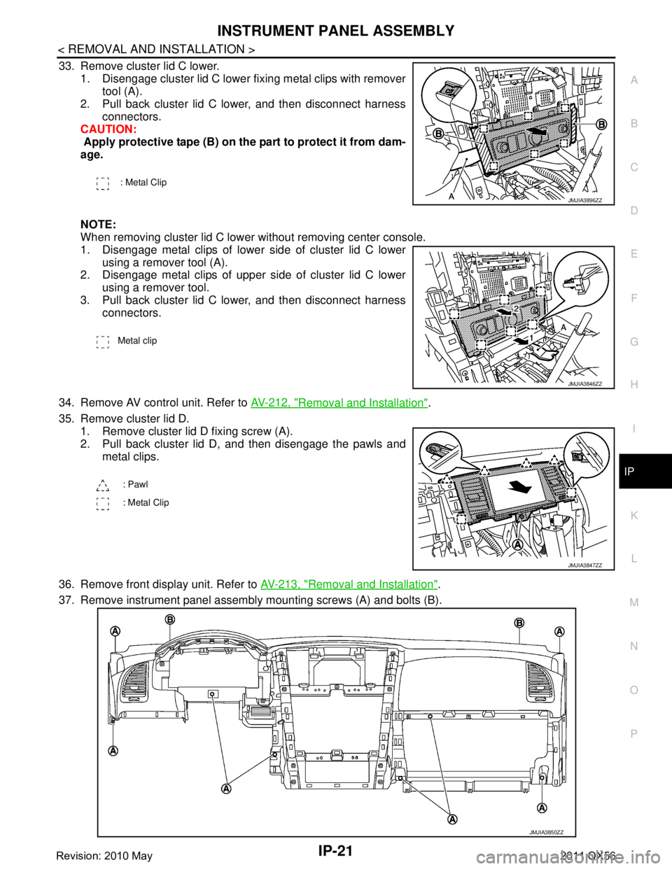
33. Remove cluster lid C lower. 1. Disengage cluster lid C lower fixing metal clips with remover tool (A).
2. Pull back cluster lid C lower, and then disconnect harness
connectors.
CAUTION:
Apply protective tape (B) on the part to protect it from dam-
age.
NOTE:
When removing cluster lid C lower without removing center console.
1. Disengage metal clips of lower side of cluster lid C lower
using a remover tool (A).
2. Disengage metal clips of upper side of cluster lid C lower
using a remover tool.
3. Pull back cluster lid C lower, and then disconnect harness connectors.
34. Remove AV control unit. Refer to AV-212, "
Removal and Installation".
35. Remove cluster lid D. 1. Remove cluster lid D fixing screw (A).
2. Pull back cluster lid D, and then disengage the pawls and metal clips.
36. Remove front display unit. Refer to AV-213, "
Removal and Installation".
37. Remove instrument panel assembly mounting screws (A) and bolts (B).
: Metal Clip
JMJIA3896ZZ
Metal clip
JMJIA3846ZZ
: Pawl
: Metal Clip
JMJIA3847ZZ
JMJIA3850ZZ
Revision: 2010 May2011 QX56
Page 3412 of 5598

IP-22
< REMOVAL AND INSTALLATION >
INSTRUMENT PANEL ASSEMBLY
38. Pull back instrument panel assembly, and then remove front squawker LH harness (1) fixing clip (A) fromfront ventilator duct (2).
39. Remove instrument panel from passenger door opening portion. CAUTION:
Cover tool with a shop cloth to pr event windshield glass from being damaged.
When removing instrument panel assembly, 2 worker s are required so as to prevent it from drop-
ping.
40. Remove the following parts after removing instrument panel assembly. Front passenger air bag module. Refer to SR-17, "
Removal and Installation".
Side ventilator grille LH/RH. Refer to VTL-10, "
SIDE VENTILATOR GRILLE : Removal and Installation".
Side ventilator duct: Refer to VTL-10, "
SIDE VENTILATOR DUCT : Removal and Installation".
Upper ventilator duct: Refer to VTL-10, "
UPPER VENTILATOR DUCT : Removal and Installation".
Front defroster nozzle: Refer to VTL-11, "
FRONT DEFROSTER NOZZLE : Removal and Installation".
Side defroster nozzle: Refer to VTL-11, "
SIDE DEFROSTER NOZZLE : Removal and Installation".
GPS antenna: Refer to AV-232, "
Removal and Installation".
Instrument finisher A
Instrument finisher B
INSTALLATION
Install in the reverse order of removal.
JMJIA3851ZZ
Revision: 2010 May2011 QX56
Page 3413 of 5598
CENTER CONSOLE ASSEMBLYIP-23
< REMOVAL AND INSTALLATION >
C
DE
F
G H
I
K L
M A
B
IP
N
O P
CENTER CONSOLE ASSEMBLY
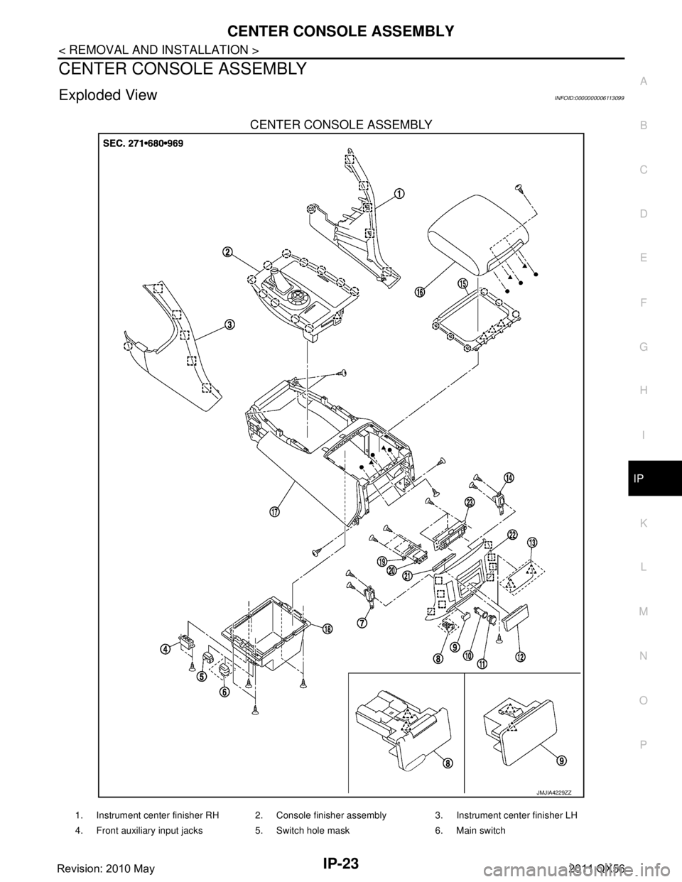
Exploded ViewINFOID:0000000006113099
CENTER CONSOLE ASSEMBLY
JMJIA4229ZZ
1. Instrument center finisher RH 2. Console finisher assembly 3. Instrument center finisher LH
4. Front auxiliary input jacks 5. Switch hole mask 6. Main switch
Revision: 2010 May2011 QX56
Page 3414 of 5598

IP-24
< REMOVAL AND INSTALLATION >
CENTER CONSOLE ASSEMBLY
CONSOLE FINISHER ASSEMBLY
7. Second heated seat switch LH 8. 120W unit 9. Mask
10. Inner socket 11. Socket knob 12. Console ashtray
13. Mask (without ashtray) 14. Second heated seat switch RH 15. Console hinge cover
16. Console lid assembly 17. Console body assembly 18. Console box
19. Inside key antenna 20. Rear auxiliary input jacks 21. Console ashtray bracket
22. Console rear finisher 23. Rear A/C control: Clip
: Pawl
: Metal clip
JMJIA4230ZZ
1. AT control indicator assembly 2. 4WD: 4WD switch assembly 2WD: SNOW MODE/TOW MODE/
VDC OFF switch assembly3. Console pocket assembly
4. Cup holder assembly 5. Inner socket 6. Socket ring
7. Socket knob 8. USB connector 9. Inner case
10. Coin pocket : Clip
: Pawl
Revision: 2010 May2011 QX56
Page 3415 of 5598
CENTER CONSOLE ASSEMBLYIP-25
< REMOVAL AND INSTALLATION >
C
DE
F
G H
I
K L
M A
B
IP
N
O P
Removal and InstallationINFOID:0000000006113100
CAUTION:
When removing, always use a remover tool that is made of plastic.
REMOVAL
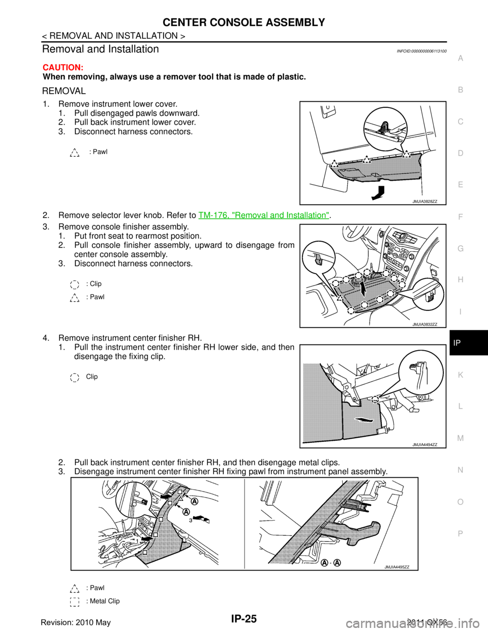
1. Remove instrument lower cover.
1. Pull disengaged pawls downward.
2. Pull back instrument lower cover.
3. Disconnect harness connectors.
2. Remove selector lever knob. Refer to TM-176, "
Removal and Installation".
3. Remove console finisher assembly. 1. Put front seat to rearmost position.
2. Pull console finisher assembly, upward to disengage from center console assembly.
3. Disconnect harness connectors.
4. Remove instrument center finisher RH. 1. Pull the instrument center finisher RH lower side, and then disengage the fixing clip.
2. Pull back instrument center finisher RH, and then disengage metal clips.
3. Disengage instrument center finisher RH fixi ng pawl from instrument panel assembly.
: Pawl
JMJIA3828ZZ
: Clip
: Pawl
JMJIA3832ZZ
Clip
JMJIA4494ZZ
: Pawl
: Metal Clip
JMJIA4495ZZ
Revision: 2010 May2011 QX56
Page 3416 of 5598
IP-26
< REMOVAL AND INSTALLATION >
CENTER CONSOLE ASSEMBLY
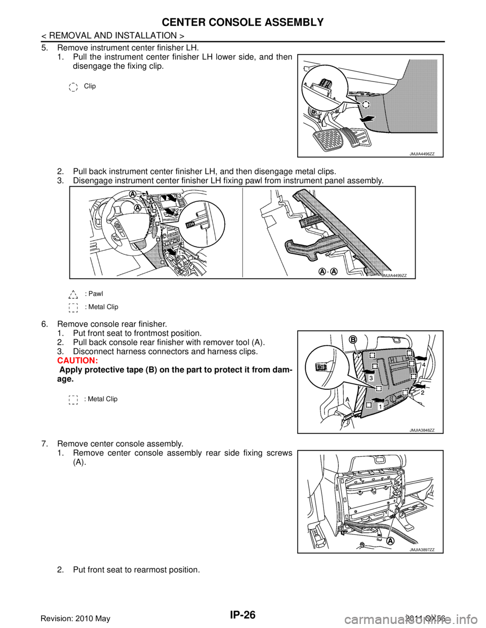
5. Remove instrument center finisher LH.1. Pull the instrument center finisher LH lower side, and thendisengage the fixing clip.
2. Pull back instrument center finisher LH, and then disengage metal clips.
3. Disengage instrument center finisher LH fi xing pawl from instrument panel assembly.
6. Remove console rear finisher. 1. Put front seat to frontmost position.
2. Pull back console rear finisher with remover tool (A).
3. Disconnect harness connectors and harness clips.
CAUTION:
Apply protective tape (B) on the part to protect it from dam-
age.
7. Remove center console assembly. 1. Remove center console assembly rear side fixing screws
(A).
2. Put front seat to rearmost position.
Clip
JMJIA4496ZZ
: Pawl
: Metal Clip
JMJIA4499ZZ
: Metal Clip
JMJIA3848ZZ
JMJIA3897ZZ
Revision: 2010 May2011 QX56
Page 3417 of 5598
CENTER CONSOLE ASSEMBLYIP-27
< REMOVAL AND INSTALLATION >
C
DE
F
G H
I
K L
M A
B
IP
N
O P
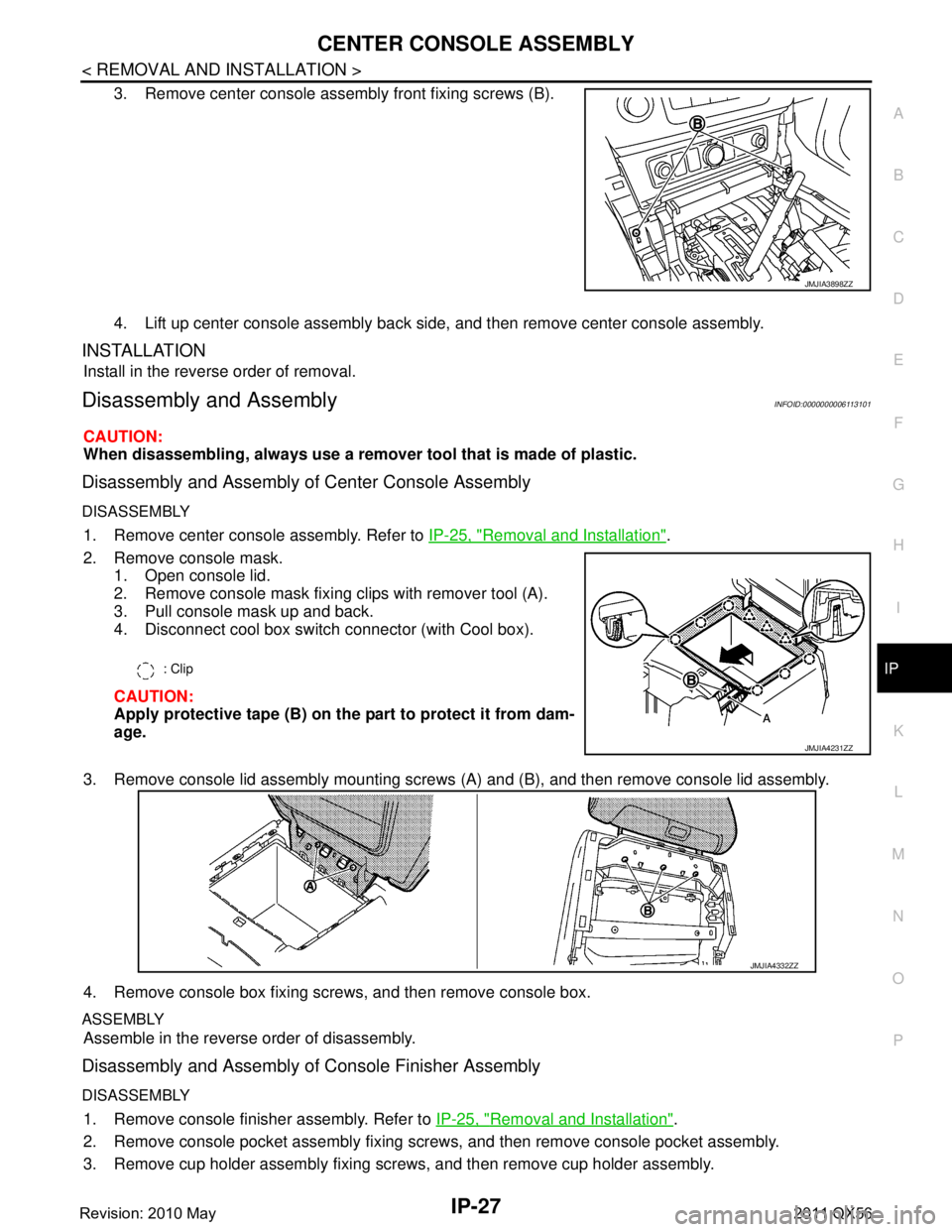
3. Remove center console assembly front fixing screws (B).
4. Lift up center console assembly back side, and then remove center console assembly.
INSTALLATION
Install in the reverse order of removal.
Disassembly and AssemblyINFOID:0000000006113101
CAUTION:
When disassembling, always use a remover tool that is made of plastic.
Disassembly and Assembly of Center Console Assembly
DISASSEMBLY
1. Remove center console assembly. Refer to IP-25, "Removal and Installation".
2. Remove console mask. 1. Open console lid.
2. Remove console mask fixing clips with remover tool (A).
3. Pull console mask up and back.
4. Disconnect cool box switch connector (with Cool box).
CAUTION:
Apply protective tape (B) on the part to protect it from dam-
age.
3. Remove console lid assembly mounting screws (A) and (B), and then remove console lid assembly.
4. Remove console box fixing screws, and then remove console box.
ASSEMBLY
Assemble in the reverse order of disassembly.
Disassembly and Assembly of Console Finisher Assembly
DISASSEMBLY
1. Remove console finisher assembly. Refer to IP-25, "Removal and Installation".
2. Remove console pocket assembly fixing screws, and then remove console pocket assembly.
3. Remove cup holder assembly fixing screws, and then remove cup holder assembly.
JMJIA3898ZZ
: Clip
JMJIA4231ZZ
JMJIA4332ZZ
Revision: 2010 May2011 QX56
Page 3418 of 5598

IP-28
< REMOVAL AND INSTALLATION >
CENTER CONSOLE ASSEMBLY
4. Remove console power socket. Refer to PWO-11, "CONSOLE POWER SOCKET (REAR) : Removal and
Installation".
5. Remove 4WD switch assembly (2WD: SNOW MODE/TOW MODE/VDC OFF switch assembly). Refer to DLN-108, "
Removal and Installation".
ASSEMBLY
Assemble in the reverse order of disassembly.
Revision: 2010 May2011 QX56
Page 3419 of 5598
REAR CONSOLE ASSEMBLYIP-29
< REMOVAL AND INSTALLATION >
C
DE
F
G H
I
K L
M A
B
IP
N
O P
REAR CONSOLE ASSEMBLY
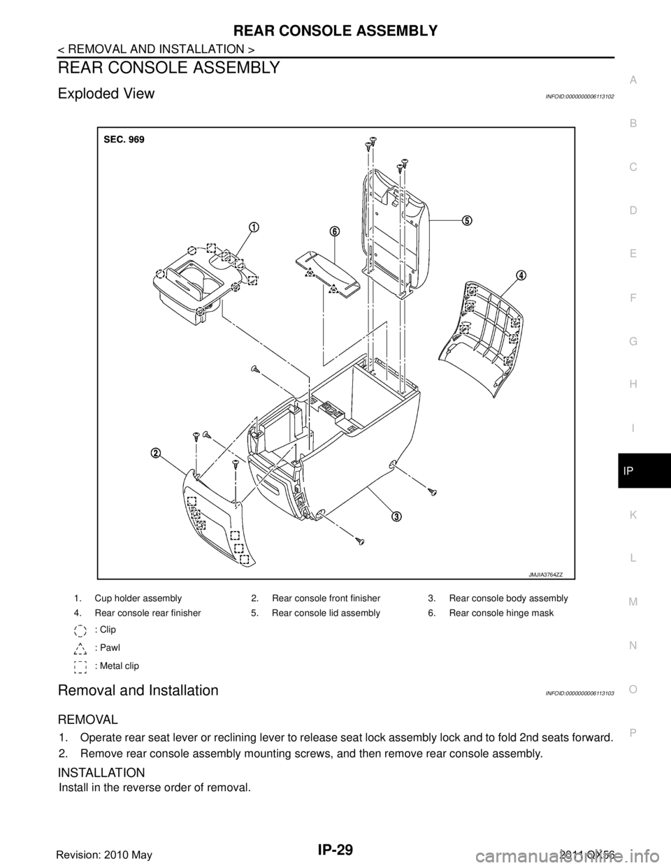
Exploded ViewINFOID:0000000006113102
Removal and InstallationINFOID:0000000006113103
REMOVAL
1. Operate rear seat lever or reclining lever to release seat lock assembly lock and to fold 2nd seats forward.
2. Remove rear console assembly mounting screws, and then remove rear console assembly.
INSTALLATION
Install in the reverse order of removal.
1. Cup holder assembly 2. Rear console front finisher 3. Rear console body assembly
4. Rear console rear finisher 5. Rear console lid assembly 6. Rear console hinge mask : Clip
: Pawl
: Metal clip
JMJIA3764ZZ
Revision: 2010 May2011 QX56
Page 3420 of 5598
IP-30
< REMOVAL AND INSTALLATION >
REAR CONSOLE ASSEMBLY
Disassembly and Assembly
INFOID:0000000006113104
CAUTION:
When disassembling, always use a remover tool that is made of plastic.
DISASSEMBLY
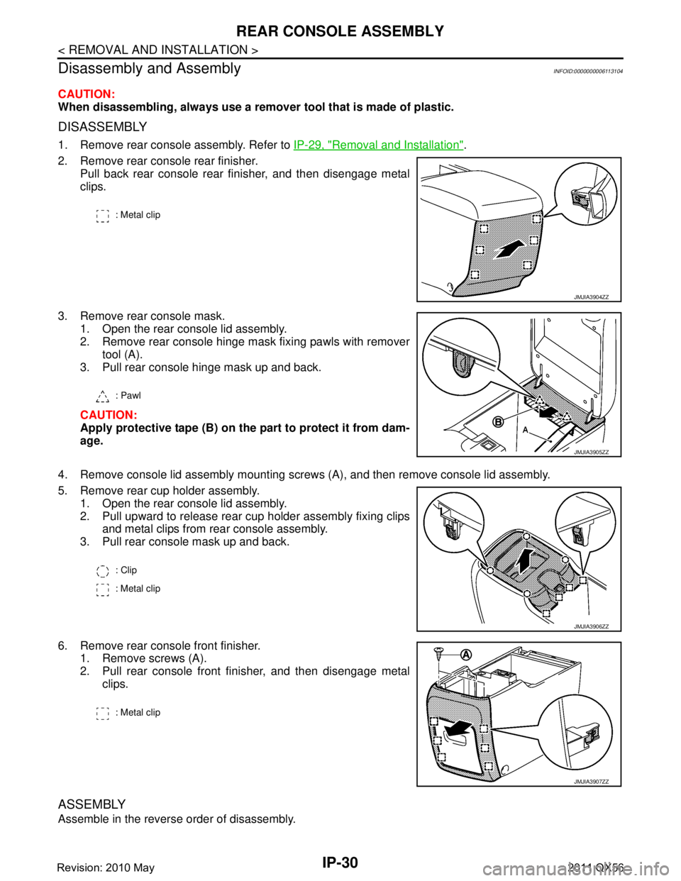
1. Remove rear console assembly. Refer to IP-29, "Removal and Installation".
2. Remove rear console rear finisher. Pull back rear console rear finisher, and then disengage metal
clips.
3. Remove rear console mask. 1. Open the rear console lid assembly.
2. Remove rear console hinge mask fixing pawls with removertool (A).
3. Pull rear console hinge mask up and back.
CAUTION:
Apply protective tape (B) on the part to protect it from dam-
age.
4. Remove console lid assembly mounting screws (A), and then remove console lid assembly.
5. Remove rear cup holder assembly. 1. Open the rear console lid assembly.
2. Pull upward to release rear cup holder assembly fixing clipsand metal clips from rear console assembly.
3. Pull rear console mask up and back.
6. Remove rear console front finisher. 1. Remove screws (A).
2. Pull rear console front finisher, and then disengage metal
clips.
ASSEMBLY
Assemble in the reverse order of disassembly.
: Metal clip
JMJIA3904ZZ
: Pawl
JMJIA3905ZZ
: Clip
: Metal clip
JMJIA3906ZZ
: Metal clip
JMJIA3907ZZ
Revision: 2010 May2011 QX56