rsu INFINITI QX56 2011 Factory Owner's Guide
[x] Cancel search | Manufacturer: INFINITI, Model Year: 2011, Model line: QX56, Model: INFINITI QX56 2011Pages: 5598, PDF Size: 94.53 MB
Page 4272 of 5598

REAR STABILIZERRSU-17
< REMOVAL AND INSTALLATION >
C
DF
G H
I
J
K L
M A
B
RSU
N
O P
REAR STABILIZER
Exploded ViewINFOID:0000000006270956
Removal and InstallationINFOID:0000000006270957
REMOVAL
1. Remove stabilizer connecting rods.
2. Remove stabilizer clamps and stabilizer bushings.
3. Remove stabilizer bar.
4. Perform inspection after removal. Refer to RSU-17, "
Inspection".
INSTALLATION
Note the following, and install in the reverse order of removal.
Tighten the mounting nut to the specified torque wh ile holding a hexagonal part of stabilizer connecting rod
side.
InspectionINFOID:0000000006270958
INSPECTION AFTER REMOVAL
Check stabilizer bar, stabilizer connecting rod, stabiliz er bushing and stabilizer clamp for deformation, cracks
or damage. Replace it if necessary.
1. Stabilizer bar 2. Stabilizer bushing 3. Stabilizer clamp
4. Stabilizer connecting rod 5. Front lower link
Refer to GI-4, "
Components" for symbols in the figure.
JPEIB0249GB
Revision: 2010 May2011 QX56
Page 4273 of 5598

RSU-18
< UNIT REMOVAL AND INSTALLATION >
REAR SUSPENSION MEMBER
UNIT REMOVAL AND INSTALLATION
REAR SUSPENSION MEMBER
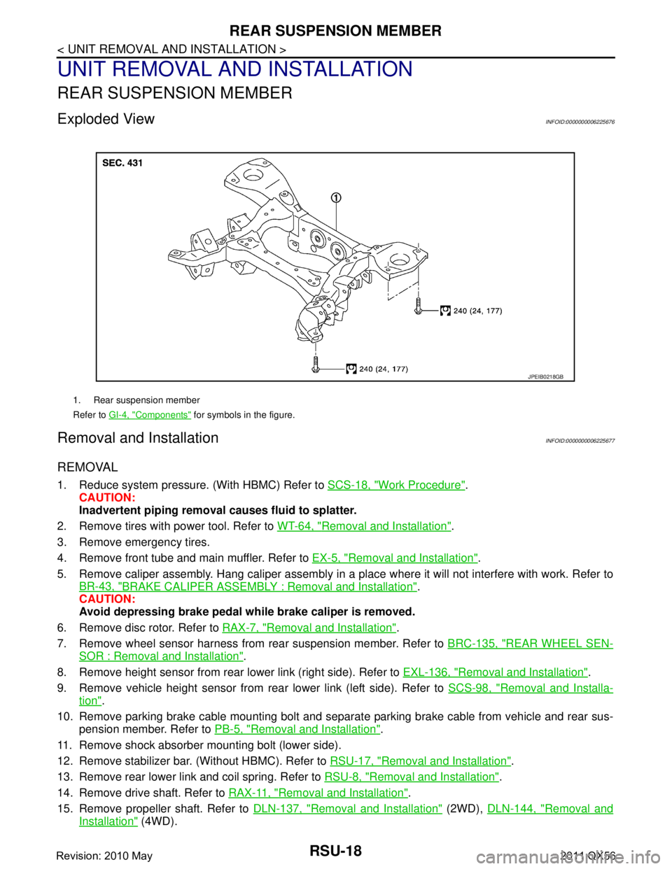
Exploded ViewINFOID:0000000006225676
Removal and InstallationINFOID:0000000006225677
REMOVAL
1. Reduce system pressure. (With HBMC) Refer to SCS-18, "Work Procedure".
CAUTION:
Inadvertent piping removal causes fluid to splatter.
2. Remove tires with power tool. Refer to WT-64, "
Removal and Installation".
3. Remove emergency tires.
4. Remove front tube and main muffler. Refer to EX-5, "
Removal and Installation".
5. Remove caliper assembly. Hang caliper assembly in a place where it will not interfere with work. Refer to BR-43, "
BRAKE CALIPER ASSEMBLY : Removal and Installation".
CAUTION:
Avoid depressing brake pedal wh ile brake caliper is removed.
6. Remove disc rotor. Refer to RAX-7, "
Removal and Installation".
7. Remove wheel sensor harness from rear suspension member. Refer to BRC-135, "
REAR WHEEL SEN-
SOR : Removal and Installation".
8. Remove height sensor from rear lower link (right side). Refer to EXL-136, "
Removal and Installation".
9. Remove vehicle height sensor from rear lower link (left side). Refer to SCS-98, "
Removal and Installa-
tion".
10. Remove parking brake cable mounting bolt and separa te parking brake cable from vehicle and rear sus-
pension member. Refer to PB-5, "
Removal and Installation".
11. Remove shock absorber mounting bolt (lower side).
12. Remove stabilizer bar. (Without HBMC). Refer to RSU-17, "
Removal and Installation".
13. Remove rear lower link and coil spring. Refer to RSU-8, "
Removal and Installation".
14. Remove drive shaft. Refer to RAX-11, "
Removal and Installation".
15. Remove propeller shaft. Refer to DLN-137, "
Removal and Installation" (2WD), DLN-144, "Removal and
Installation" (4WD).
1. Rear suspension member
Refer to GI-4, "
Components" for symbols in the figure.
JPEIB0218GB
Revision: 2010 May2011 QX56
Page 4274 of 5598

REAR SUSPENSION MEMBERRSU-19
< UNIT REMOVAL AND INSTALLATION >
C
DF
G H
I
J
K L
M A
B
RSU
N
O P
16. Remove final drive. Refer to DLN-201, "Removal and Installation".
17. Remove rear tube assembly A and rear tube assembly B. (With HBMC) Refer to SCS-44, "
REAR TUBE
ASSEMBLY : Removal and Installation".
18. Set suitable jack under rear suspension member.
19. Slowly lower jack, then remove rear suspension member, suspension arm, front lower link, wheel hub and housing from vehicle as a unit.
20. Remove mounting bolts and nuts, then remove suspension arm, front lower link, wheel hub and housing from rear suspension member.
21. Perform inspection after removal. Refer to RSU-19, "
Inspection and Adjustment".
INSTALLATION
Note the following, and install in the reverse order of the removal.
Perform the final tightening of each of parts under unladen conditions, which were removed when removing
rear suspension assembly.
Perform inspection after installation. Refer to RSU-19, "
Inspection and Adjustment".
Perform adjustment after installation. (With HBMC) Refer to RSU-19, "
Inspection and Adjustment".
Inspection and AdjustmentINFOID:0000000006225678
INSPECTION AFTER REMOVAL
Check rear suspension member for deformation, cracks, or any other damage. Replace if necessary.
INSPECTION AFTER INSTALLATION
1. Adjust parking brake operation (stroke). Refer to PB-3, "Inspection and Adjustment".
2. Check wheel alignment. Refer to RSU-6, "
Inspection".
3. Adjust neutral position of steering angle sensor. Refer to BRC-64, "
Work Procedure".
4. Adjust levelizer adjustment of height sensor. Refer to EXL-61, "
LEVELIZER ADJUSTMENT : Special
Repair Requirement".
5. Check standard vehicle height setting of vehicle height sensor. Refer to SCS-67, "
Work Procedure".
6. Check wheel sensor harness for proper connection. Refer to BRC-135, "
REAR WHEEL SENSOR :
Exploded View"
ADJUSTMENT AFTER INSTALLATION (WITH HBMC)
Bleed air from the HBMC. Refer to SCS-18, "Work Procedure".
Revision: 2010 May2011 QX56
Page 4275 of 5598

RSU-20
< SERVICE DATA AND SPECIFICATIONS (SDS)
SERVICE DATA AND SPECIFICATIONS (SDS)
SERVICE DATA AND SPECIFICATIONS (SDS)
SERVICE DATA AND SPECIFICATIONS (SDS)
Wheel AlignmentINFOID:0000000006225679
Measure value under unladen* conditions.
*: Fuel, engine coolant and lubricant are full. Spare tire, jack, hand tools and mats are in designated positions.
Ball JointINFOID:0000000006225680
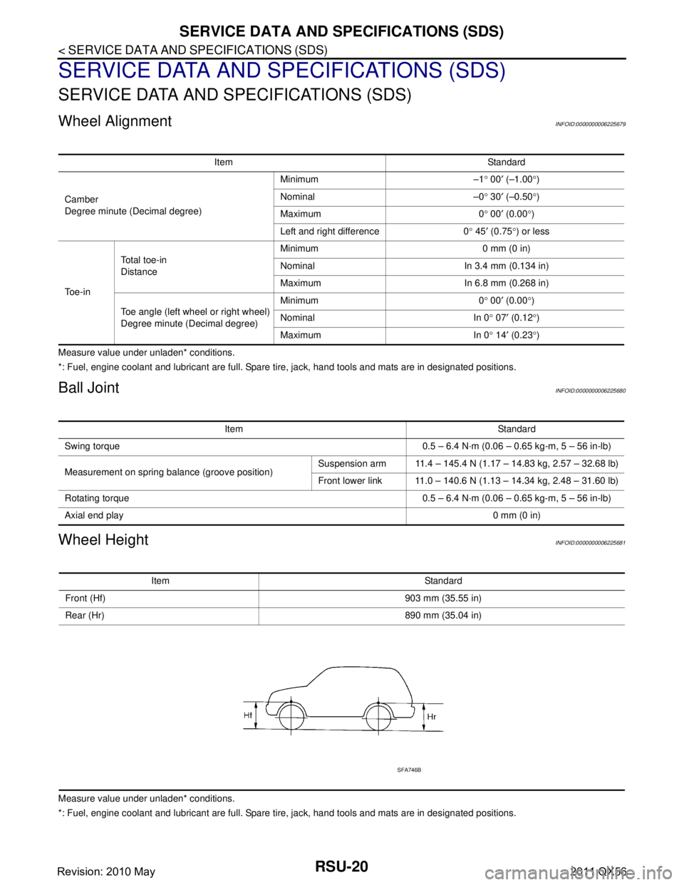
Wheel HeightINFOID:0000000006225681
Measure value under unladen* conditions.
*: Fuel, engine coolant and lubricant are full. Spare tire, jack, hand tools and mats are in designated positions.Item Standard
Camber
Degree minute (Decimal degree) Minimum –1
° 00 ′ (–1.00 °)
Nominal –0 ° 30 ′ (–0.50 °)
Maximum 0 ° 00 ′ (0.00 °)
Left and right difference 0 ° 45 ′ (0.75 °) or less
To e - i n Total toe-in
Distance
Minimum 0 mm (0 in)
Nominal In 3.4 mm (0.134 in)
Maximum In 6.8 mm (0.268 in)
Toe angle (left wheel or right wheel)
Degree minute (Decimal degree) Minimum 0
° 00 ′ (0.00 °)
Nominal In 0 ° 07 ′ (0.12 °)
Maximum In 0 ° 14 ′ (0.23 °)
Item Standard
Swing torque 0.5 – 6.4 N·m (0.06 – 0.65 kg-m, 5 – 56 in-lb)
Measurement on spring balance (groove position) Suspension arm 11.4 – 145.4 N (1.17 – 14.83 kg, 2.57 – 32.68 lb)
Front lower link 11.0 – 140.6 N (1.13 – 14.34 kg, 2.48 – 31.60 lb)
Rotating torque 0.5 – 6.4 N·m (0.06 – 0.65 kg-m, 5 – 56 in-lb)
Axial end play 0 mm (0 in)
Item Standard
Front (Hf) 903 mm (35.55 in)
Rear (Hr) 890 mm (35.04 in)
SFA746B
Revision: 2010 May2011 QX56
Page 4385 of 5598
![INFINITI QX56 2011 Factory Owners Guide
CHECK SHOCK ABSORBER FOR MALFUNCTIONSCS-25
< BASIC INSPECTION > [HBMC]
C
D
F
G H
I
J
K L
M A
B
SCS
N
O P
- Disconnect upper side pipe (B) of front shock absorber.
For rear shock absorber
- Disconne INFINITI QX56 2011 Factory Owners Guide
CHECK SHOCK ABSORBER FOR MALFUNCTIONSCS-25
< BASIC INSPECTION > [HBMC]
C
D
F
G H
I
J
K L
M A
B
SCS
N
O P
- Disconnect upper side pipe (B) of front shock absorber.
For rear shock absorber
- Disconne](/img/42/57033/w960_57033-4384.png)
CHECK SHOCK ABSORBER FOR MALFUNCTIONSCS-25
< BASIC INSPECTION > [HBMC]
C
D
F
G H
I
J
K L
M A
B
SCS
N
O P
- Disconnect upper side pipe (B) of front shock absorber.
For rear shock absorber
- Disconnect lower side pipe (B ) of rear shock absorber.
9. Install a leak check plug (SST: KV40108400) (A) to the removed pipe and tighten the leak check plug to the specified torque.
CAUTION:
O-ring must be free of scratches and damage.
Piping must be kept free of the intrusion of dust and dirt.
10. Loosen lock nuts of needle valves B and D of PPMU and then tighten needle valves B and D.
11. Loosening position of needle valve of PPMU varies according to shock absorber that is che cked. Loosen needle valve of PPMU
by approximately 2 rotations, as per the following table.
CAUTION:
Never loosen the needle valve more than required.
12. Set knob (A) of suspension oil pump to the direction as shown in the figure.
13. Apply pressure of up to 2.4 MPa.
14. Go to step 15 when oil comes out from lower portion of shock absorber which pipe is removed from. Go to step 16 when oil
does not come out.
15. Replace shock absorber, since shock absorber has internal leakage. Refer to FSU-10, "
Removal and Installation" (front),
RSU-8, "
Removal and Installation" (rear).
A : Lower side pipe
JSEIA0233ZZ
A : Upper side pipe
JSEIA0203ZZ
Tightening torque : 5.0 N·m (0.51 kg-m, 44 in-lb)
Shock absorber Loosening position of needle valve
Front LH C
Rear LH C
Front RH A
Rear RH A
JSEIA0210ZZ
JSEIA0191ZZ
Revision: 2010 May2011 QX56
Page 4390 of 5598
![INFINITI QX56 2011 Factory Owners Guide
SCS-30
< SYMPTOM DIAGNOSIS >[HBMC]
LARGE ROLL ANGLE
LARGE ROLL ANGLE
DescriptionINFOID:0000000006256018
During cornering, inclination of the vehi
cle to outer side of corner is large.
Inspection Pro INFINITI QX56 2011 Factory Owners Guide
SCS-30
< SYMPTOM DIAGNOSIS >[HBMC]
LARGE ROLL ANGLE
LARGE ROLL ANGLE
DescriptionINFOID:0000000006256018
During cornering, inclination of the vehi
cle to outer side of corner is large.
Inspection Pro](/img/42/57033/w960_57033-4389.png)
SCS-30
< SYMPTOM DIAGNOSIS >[HBMC]
LARGE ROLL ANGLE
LARGE ROLL ANGLE
DescriptionINFOID:0000000006256018
During cornering, inclination of the vehi
cle to outer side of corner is large.
Inspection ProcedureINFOID:0000000006256019
1.CHECK APPEARANCE
1. Visually check that the exterior parts (e.g. suspension spring) have no malfunctions.
2. Visually check tube and pipe for crush or oil leakage.
Is the inspection result normal?
YES >> GO TO 2.
NO >> Repair or replace damaged parts.
2.CHECK NEEDLE VALVE OF PPMU
Check that needle valves A and C are tightened to the specified
torque.
Is the inspection result normal?
YES >> GO TO 3.
NO >> Tighten to the specified torque.
3.SYSTEM PRESSURE CHECK
Check system pressure. Refer to SCS-15, "
Work Procedure".
Is the inspection result normal?
YES >> GO TO 4.
NO >> Perform adjustment of system pressure. Refer to SCS-18, "
Work Procedure".
4.CHECK INTERNAL LEAKAGE
Check internal leakage. Refer to SCS-20, "
Work Procedure".
Is the inspection result normal?
YES >> INSPECTION END
NO >> GO TO 5.
5.CHECK MALFUNCTIONING PART
Identify malfunctioning part. Refer to SCS-22, "
Work Procedure".
Does the pressure increase?
YES >> Replace the PPMU. Refer to SCS-39, "PPMU, MIDDLE TUBE ASSEMBLY, PPMU PIPE :
Removal and Installation".
NO >> GO TO 6.
6.CHECK SHOCK ABSORBER
Identify malfunctioning shock absorber. Refer to SCS-24, "
Work Procedure".
>> Replace identified shock absorber. Refer to FSU-10, "
Removal and Installation" (front), RSU-8,
"Removal and Installation" (rear).
Tightening torque : 8.3 N·
m (0.85 kg-m, 73 in-lb)
JSEIA0187ZZ
Revision: 2010 May2011 QX56
Page 5016 of 5598

NOISE, VIBRATION AND HARSHNESS (NVH) TROUBLESHOOTINGST-29
< SYMPTOM DIAGNOSIS >
C
DE
F
H I
J
K L
M A
B
ST
N
O P
NOISE, VIBRATION AND HARSHN ESS (NVH) TROUBLESHOOTING
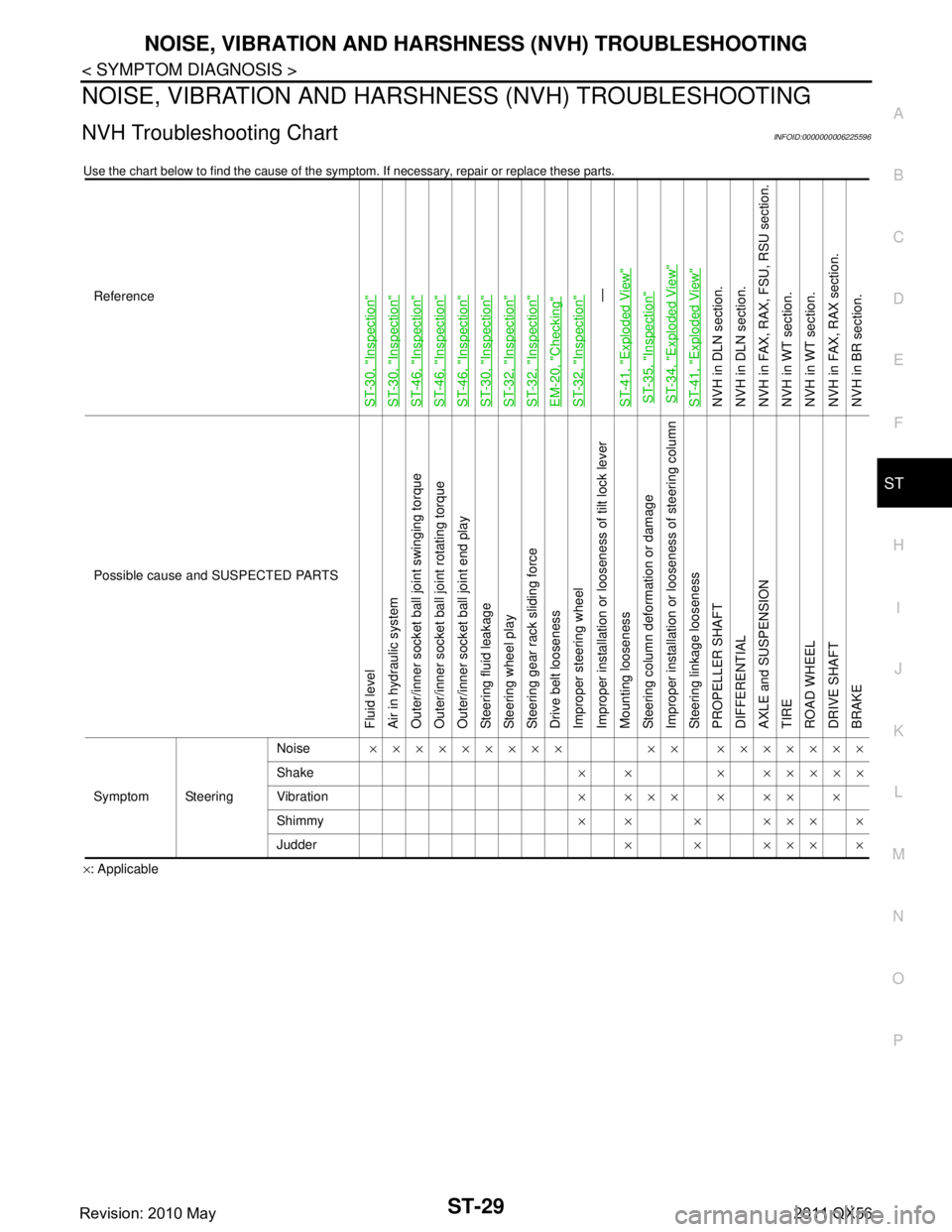
NVH Troubleshooting ChartINFOID:0000000006225596
Use the chart below to find the cause of the symp tom. If necessary, repair or replace these parts.
×: ApplicableReference
ST-30, "
Inspection
"
ST-30, "
Inspection
"
ST-46, "
Inspection
"
ST-46, "
Inspection
"
ST-46, "
Inspection
"
ST-30, "
Inspection
"
ST-32, "
Inspection
"
ST-32, "
Inspection
"
EM-20, "
Checking
"
ST-32, "
Inspection
"—
ST-41, "
Exploded View
"
ST-35, "
Inspection
"
ST-34, "
Exploded View
"
ST-41, "
Exploded View
"
NVH in DLN section.
NVH in DLN section.
NVH in FAX, RAX, FSU, RSU section.
NVH in WT section.
NVH in WT section.
NVH in FAX, RAX section.
NVH in BR section.
Possible cause and SUSPECTED PARTS
Fluid level
Air in hydraulic system
Outer/inner socket ball joint swinging torque
Outer/inner socket ball joint rotating torque
Outer/inner socket ball joint end play
Steering fluid leakage
Steering wheel play
Steering gear rack sliding force
Drive belt looseness
Improper steering wheel
Improper installation or looseness of tilt lock lever
Mounting looseness
Steering column deformation or damage
Improper installation or looseness of steering column
Steering linkage looseness
PROPELLER SHAFT
DIFFERENTIAL
AXLE and SUSPENSION
TIRE
ROAD WHEEL
DRIVE SHAFT
BRAKE
Symptom Steering Noise
××××××××× ×× ×××××××
Shake × × × ×××××
Vibration ××××××××
Shimmy ×× × ××××
Judder ××××××
Revision: 2010 May2011 QX56
Page 5511 of 5598

NOISE, VIBRATION AND HARSHNESS (NVH) TROUBLESHOOTINGWT-61
< SYMPTOM DIAGNOSIS >
C
DF
G H
I
J
K L
M A
B
WT
N
O P
NOISE, VIBRATION AND HARSHN ESS (NVH) TROUBLESHOOTING
NVH Troubleshooting ChartINFOID:0000000006225544
Use the chart below to find the cause of the symp tom. If necessary, repair or replace these parts.
×: ApplicableReference
WT-64, "
Exploded View
"
WT-64, "
Inspection
"
WT-62, "
Adjustment
"
WT-69, "
Tire Air Pressure
"
WT-64, "
Inspection
"
—
—
WT-69, "
Tire Air Pressure
"
NVH in DLN section.
NVH in DLN section.
NVH in FAX and FSU sections.
NVH in RAX and RSU sections.
Refer to TIRES in this chart.
Refer to ROAD WHEEL in this chart.
NVH in FAX, RAX section.
NVH in BR section.
NVH in ST section.
Possible cause and SUSPECTED PARTS
Improper installation, looseness
Out-of-round
Unbalance
Incorrect tire pressure
Uneven tire wear
Deformation or damage
Non-uniformity
Incorrect tire size
PROPELLER SHAFT
DIFFERENTIAL
FRONT AXLE AND FRONT SUSPENSION
REAR AXLE AND REAR SUSPENSION
TIRES
ROAD WHEELS
DRIVE SHAFT
BRAKE
STEERING
Symptom TIRESNoise
××××××× ×××× ××××
Shake ×××××× ×× ×× ××××
Vibration ×××××××
Shimmy ×××××××× ×× × ××
Judder ×
××××× × ×× × ××
Poor quality ride or
handling ×××××× × × ××
ROAD
WHEEL Noise
××× × ××××× ×××
Shake ××× × × ××× ×××
Shimmy, Judder ××× × ××× ××
Poor quality ride or
handling ××× × ×××
Revision: 2010 May2011 QX56