tow INFINITI QX56 2011 Factory Owner's Guide
[x] Cancel search | Manufacturer: INFINITI, Model Year: 2011, Model line: QX56, Model: INFINITI QX56 2011Pages: 5598, PDF Size: 94.53 MB
Page 2726 of 5598
![INFINITI QX56 2011 Factory Owners Guide
EXL-16
< SYSTEM DESCRIPTION >[XENON TYPE]
SYSTEM
- Swivels the headlamp to the vehicle-center side until it hits the stopper.
- Returns the swivel angle from the stopper. Completes t
he initializatio INFINITI QX56 2011 Factory Owners Guide
EXL-16
< SYSTEM DESCRIPTION >[XENON TYPE]
SYSTEM
- Swivels the headlamp to the vehicle-center side until it hits the stopper.
- Returns the swivel angle from the stopper. Completes t
he initializatio](/img/42/57033/w960_57033-2725.png)
EXL-16
< SYSTEM DESCRIPTION >[XENON TYPE]
SYSTEM
- Swivels the headlamp to the vehicle-center side until it hits the stopper.
- Returns the swivel angle from the stopper. Completes t
he initialization with regarding the returned position
as the swivel angle 0 ° (straight-forward position).
Swivel Operation
AFS control unit transmits the drive signal to the sw ivel actuator when activation conditions are satisfied.
And swivels the headlamp.
- The swivel starts after steering approximately 20 ° or more from straight-forward position.
NOTE:
The steering angle differs between right turn and left turn.
- The swivel angle becomes the maximum angle toward t he driving direction if the steering angle is approxi-
mately 90 ° or more depending on the vehicle speed. The swivel angle is maintained by shutting off the drive
signal.
- The swivel starts, and returns to the swivel angle 0 ° (straight-forward position) when the steering is returned
to the straight-forward position.
AFS control unit returns the swivel angle to the strai ght-forward position, and stops the swivel regardless of
the steering angle if the operation condition is not satisfied while the swivel angle is 0°.
AFS OFF Indicator Lamp
AFS control unit transmits AFS OFF indicator lamp signal to the combination meter via CAN communication.
Combination meter turns AFS OFF indicator lamp ON /OFF/blinking according to AFS OFF indicator lamp
signal.
- AFS OFF indicator lamp is turned ON for 1 second for the AFS OFF indicator lamp bulb check when the igni-
tion switch is turned ON. AFS OFF indicator lamp is turned OFF within 1 second when the engine starts.
- AFS OFF indicator lamp turns ON when AFS is switched to “OFF” by operating AFS switch.
- AFS OFF indicator lamp blinks (1 second each) if AFS control unit detects a specific DTC.
NOTE:
Combination meter blinks AFS OFF indicator lamp (approximately 1 second each) if AFS OFF indicator
lamp signal is not received from AFS control unit.
HEADLAMP AUTO AIMING
Headlamp Auto Aiming Control Description
AFS control unit controls the headl amp light axis height appropriately according to the vehicle height.
AFS control unit detects the vehicle condition necessa ry for headlamp auto aiming control with the following
signals.
- Height sensor signals (front and rear)
- Vehicle speed signal (received from combination meter via CAN communication)
- Low beam status signal (received from IPDM E/R via CAN communication)
- Engine speed signal (received from ECM via CAN communication)
When the operation conditions are satisfied, AFS cont rol unit transmits the aiming motor drive signal for
adjusting the headlamp axis height.
Headlamp auto aiming operation condition- Headlamp ON
- While the engine running
- Vehicle speed (Control mode is switched according to the driving condition.)
Headlamp Auto Aiming Operation
AFS control unit calculates the vehicle pitch angle fr om the front and rear height sensor signal. AFS control
unit judges the angle for adjusting the axis gap from the preset position.
AFS control unit controls the headlamp axis by c hanging the aiming motor drive signal output according to
the front and rear vehicle height when detecting the follo wing vehicle condition. Output is maintained if other
condition than following is detected.
- Engine starts.
- Headlamp is turned ON.
- Vehicle posture becomes stable after changing the v ehicle posture change is detected with the headlamp
ON and the vehicle stopped.
- Vehicle speed is maintained with the headlamp ON and the vehicle driven.
CAUTION:
Adjusted axis position may differ from the preset position although the headlamp auto aiming acti-
vates properly if the suspension is replaced or worn.
Revision: 2010 May2011 QX56
Page 2848 of 5598
![INFINITI QX56 2011 Factory Owners Guide
EXL-138
< REMOVAL AND INSTALLATION >[XENON TYPE]
REAR COMBINATION LAMP
REAR COMBINATION LAMP
Exploded ViewINFOID:0000000006369482
REMOVAL
DISASSEMBLY
Removal and InstallationINFOID:0000000006369483
C INFINITI QX56 2011 Factory Owners Guide
EXL-138
< REMOVAL AND INSTALLATION >[XENON TYPE]
REAR COMBINATION LAMP
REAR COMBINATION LAMP
Exploded ViewINFOID:0000000006369482
REMOVAL
DISASSEMBLY
Removal and InstallationINFOID:0000000006369483
C](/img/42/57033/w960_57033-2847.png)
EXL-138
< REMOVAL AND INSTALLATION >[XENON TYPE]
REAR COMBINATION LAMP
REAR COMBINATION LAMP
Exploded ViewINFOID:0000000006369482
REMOVAL
DISASSEMBLY
Removal and InstallationINFOID:0000000006369483
CAUTION:
Disconnect the battery negative terminal or remove the fuse.
REMOVAL
1. Remove rear combination lamp finisher.
2. Remove rear combination lamp mounting bolts.
3. Pull rear combination lamp toward vehicle outside.
4. Disconnect rear combination lamp connector.
5. Remove rear combination lamp.
1. Rear combination lamp 2. Rear combination lamp finisher
:Pawl
JMLIA1118ZZ
1. Rear combination lamp 2. Rear turn signal bulb 3. Seal packing
4. Rear turn signal bulb socket 5. Rear combination lamp harness
JMLIA1119ZZ
Revision: 2010 May2011 QX56
Page 2869 of 5598

EXT-14
< REMOVAL AND INSTALLATION >
FRONT BUMPER
4. Pull bumper molding (1) toward the direction shown in thefigure, and then disengage bumper molding fixing metal
clips (LH and RH).
5. Remove bumper molding.
4. Remove front over fender front side. Refer to EXT-26, "
Removal and Installation".
5. Remove clips of bumper upper side.
6. Remove bumper fascia assembly fixing screws (A) (LH and RH).
7. Pull bumper fascia assembly toward the vehicle outside as shown by the arrow in the figure, and then disengage the
bumper fascia assembly from bumper side brackets (LH and
RH).
8. Disconnect corner sensor harness c onnector and fog lamp harness connector.
9. Remove bumper fascia assembly. CAUTION:
When removing bumper fascia assembly, 2 workers are required so as to prevent it from dropping.
10. Remove the following parts after removing bumper fascia assembly. Front grille lower molding.
Front bumper grille.
Sonar sensor (LH and RH). Refer to AV-239, "
Removal and Installation".
Front fog lamp assembly (LH and RH). Refer to EXL-128, "
Removal and Installation" .
Front fog lamp finishers (LH and RH)
Bumper side bracket (LH and RH)
License plate bracket
11. Remove bumper upper retainer.
INSTALLATION
Note the following item, and then install in the reverse order of removal.
NOTE:
: Metal clip
JMKIA5428ZZ
JMKIA5430ZZ
: Pawl
JMKIA5431ZZ
Revision: 2010 May2011 QX56
Page 2872 of 5598

REAR BUMPEREXT-17
< REMOVAL AND INSTALLATION >
C
DE
F
G H
I
J
L
M A
B
EXT
N
O P
Removal and InstallationINFOID:0000000006367600
REMOVAL
CAUTION:
Bumper fascia is made of resin. Never apply strong force to it, and be careful to prevent contact with
oil.
1. Fully open back door assembly.
2. Remove rear combination lamp (LH and RH). Refer to EXL-138, "
Removal and Installation".
3. Remove bumper fascia fixing clips (A) and screws (B) (LH and RH).
4. Remove rear over fender fixing screws.
5. Remove bumper fascia lower mounting bolts.
6. Remove screws (A) of bumper fascia front end upper (LH and RH).
7. Pull bumper fascia assembly toward the vehicle outside as shown by the arrow in the figure, and then disengage the
bumper fascia assembly from bumper side brackets (LH and
RH).
8. Remove bumper fascia assembly. CAUTION:
When removing bumper fascia assembly, 2 workers ar e required so as to prevent it from dropping.
9. Remove the following parts after removing rear bumper fascia. Bumper side brackets (LH and RH)
Reflex reflector (LH and RH)
Bumper stay bracket (LH and RH)
Bumper stay (LH and RH)
10. Bumper lower finisher 11. Reflex reflector RH 12. Bumper stay RH
13. Bumper side stay RH 14. Energy absorber 15. Bumper side reinforcement RH
16. Bumper stay RH 17. Bumper side bracket RH
JMKIA5370ZZ
JMKIA5460ZZ
: Pawl
JMKIA5461ZZ
Revision: 2010 May2011 QX56
Page 2875 of 5598

EXT-20
< REMOVAL AND INSTALLATION >
FRONT GRILLE
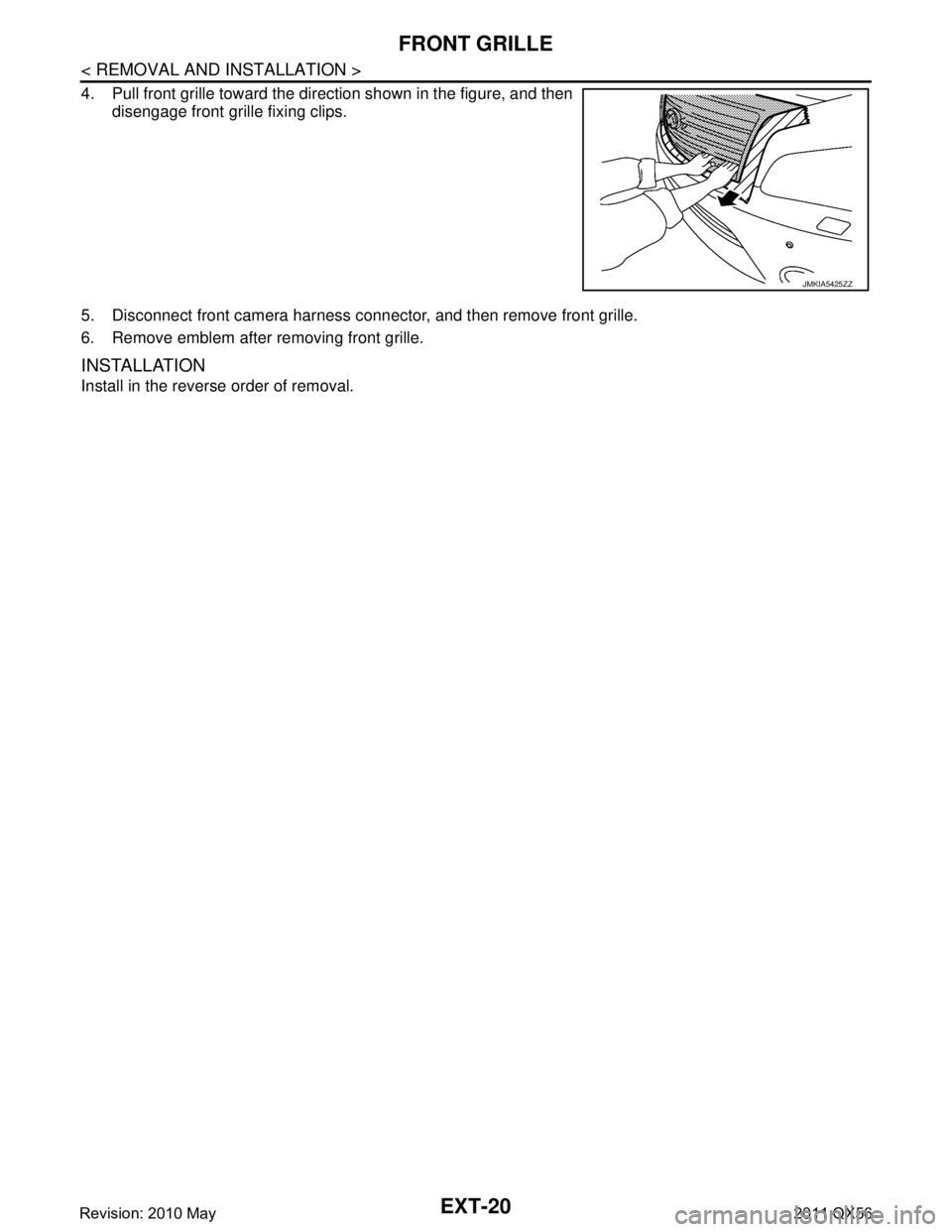
4. Pull front grille toward the direction shown in the figure, and thendisengage front grille fixing clips.
5. Disconnect front camera harness connec tor, and then remove front grille.
6. Remove emblem after removing front grille.
INSTALLATION
Install in the reverse order of removal.
JMKIA5425ZZ
Revision: 2010 May2011 QX56
Page 2882 of 5598

OVER FENDEREXT-27
< REMOVAL AND INSTALLATION >
C
DE
F
G H
I
J
L
M A
B
EXT
N
O P
3. Disengage front over fender rear side fixing pawls from behind of front fender, and the pull front over fender front side toward
the direction shown in the figure.
CAUTION:
Never pull the front over fender strongly.
4. Remove front fender protector. Refer to EXT-23, "
FENDER PROTECTOR : Removal and Installation"
5. Remove side step front side fixing clips.
6. Disengage front over fender rear side fixing pawls from behind
of fender, and then pull front over fender front side toward the
direction shown in the figure.
CAUTION:
Never pull the front over fender strongly.
7. Remove front over fender.
Rear over fender
1. Remove rear over fender rear side fixing screws and bolts.
2. Remove rear fender protector rear side. Keep the service area. Refer to EXT-24, "
REAR WHEEL HOUSE
PROTECTOR : Removal and Installation".
3. Disengage rear over fender rear side fixing pawls from behind of rear fender, and the pull rear over fender rear side toward the
direction shown in the figure.
4. Remove rear fender protctor. Refer to EXT-24, "
REAR WHEEL HOUSE PROTECTOR : Removal and
Installation".
5. Remove rear over fender front side fixing screws and bolts.
6. Using a remover tool (A), disengage the clips from the rear over fender by starting from the rear.
CAUTION:
Apply a protective tape (B) on the body to protect the
painted surface from damage.
Disengage the clips slowly and carefully.
Never pull the front o ver fender strongly.
: Pawl
JMKIA5452ZZ
: Clip
JMKIA5453ZZ
: Pawl
JMKIA5471ZZ
: Clip
JMKIA5472ZZ
Revision: 2010 May2011 QX56
Page 2934 of 5598

FUEL LEVEL SENSOR UNIT, FUEL FILTER AND FUEL PUMP ASSEMBLY
FL-5
< REMOVAL AND INSTALLATION >
C
D E
F
G H
I
J
K L
M A
FL
NP
O
REMOVAL AND INSTALLATION
FUEL LEVEL SENSOR UNIT, FUEL FI
LTER AND FUEL PUMP ASSEMBLY
Exploded ViewINFOID:0000000006289684
Removal and InstallationINFOID:0000000006289685
WARNING:
Be sure to read “General Precautions” wh en working on the fuel system. Refer to FL-2, "
General Pre-
cautions".
REMOVAL
1. Check fuel level on a level ground. If the fuel level is 7/8 of the fuel tank (full or nearly full), draw appropri-
ate amount of fuel from the fuel tank.
In the event of malfunction in fuel pump, insert a hose measuring 20mm (0.79 in) in diameter into the
filler opening to draw approximately 20 liters fuel.
2. Release the fuel pressure from the fuel lines. Refer to EC-153, "
Work Procedure".
3. Open fuel filler lid.
4. Open filler cap and release the pressure inside fuel tank.
5. Tilt the second seat toward the front of the vehicle.
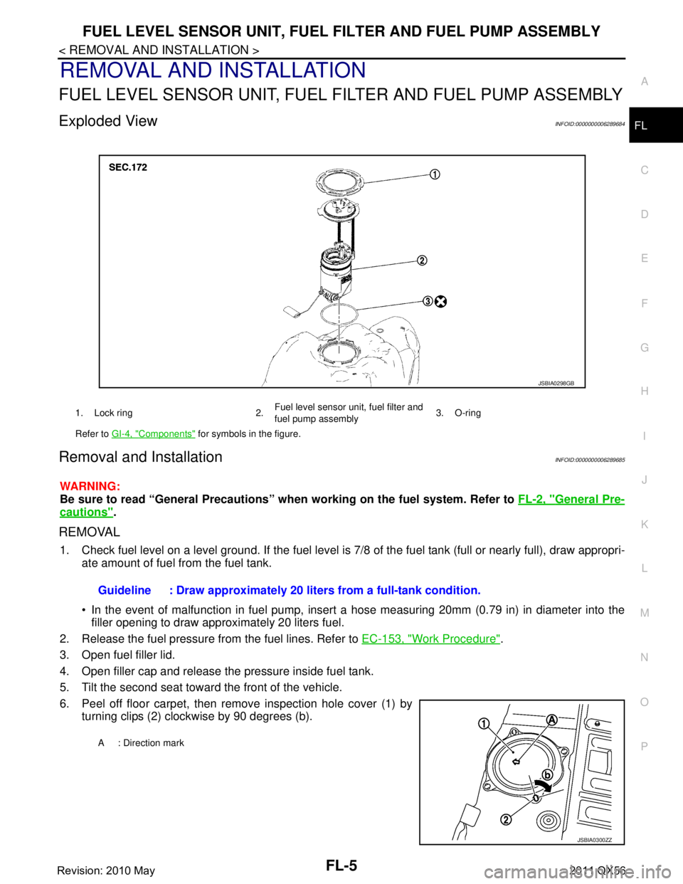
6. Peel off floor carpet, then remove inspection hole cover (1) by turning clips (2) clockwise by 90 degrees (b).
1. Lock ring 2. Fuel level sensor unit, fuel filter and
fuel pump assembly3. O-ring
Refer to GI-4, "
Components" for symbols in the figure.
JSBIA0298GB
Guideline : Draw approximately 20 li ters from a full-tank condition.
A : Direction mark
JSBIA0300ZZ
Revision: 2010 May2011 QX56
Page 2965 of 5598

GI-1
GENERAL INFORMATION
C
DE
F
G H
I
J
K L
M B
GI
SECTION GI
N
O P
CONTENTS
GENERAL INFORMATION
HOW TO USE THIS MANU AL ......................3
HOW TO USE THIS MANUAL ....................... .....3
Description .......................................................... ......3
Terms ........................................................................3
Units ..........................................................................3
Contents ....................................................................3
Relation between Illustrations and Descriptions .......4
Components ..............................................................4
HOW TO FOLLOW TROUBLE DIAGNOSES .....6
Description ................................................................6
How to Follow Test Groups in Trouble Diagnosis ......6
Key to Symbols Signifying Measurements or Pro-
cedures ............................................................... ......
7
HOW TO READ WIRING DIAGRAMS ................9
Connector Symbols ............................................. ......9
Sample/Wiring Diagram -Example- .........................10
Connector Information .............................................12
ABBREVIATIONS .......................................... ....14
Abbreviation List .................................................. ....14
TIGHTENING TORQUE OF STANDARD
BOLTS ................................................................
19
Description .......................................................... ....19
Tightening Torque Table (New Standard Includ-
ed) ...........................................................................
19
RECOMMENDED CHEMICAL PRODUCTS
AND SEALANTS ................................................
22
Recommended Chemical Products and Sealants ....22
VEHICLE INFORMATION ............................23
IDENTIFICATION INFORMATION ................. ....23
Model Variation ................................................... ....23
Information About Identification or Model Code ......23
Dimensions .............................................................25
Wheels & Tires ........................................................25
PRECAUTION ..............................................26
PRECAUTIONS .................................................26
Description ........................................................... ....26
Precaution for Supplemental Restraint System
(SRS) "AIR BAG" and "SEAT BELT PRE-TEN-
SIONER" .................................................................
26
Precautions For Xenon Headlamp Service .............26
Precaution Necessary for Steering Wheel Rota-
tion after Battery Disconnect ...................................
27
Precaution for Procedure without Cowl Top Cover ....27
General Precautions ................................................27
Three Way Catalyst .................................................29
Multiport Fuel Injection System or Engine Control
System .....................................................................
29
Hoses ......................................................................29
Engine Oils ..............................................................30
Air Conditioning .......................................................31
Fuel ..........................................................................31
LIFTING POINT .................................................32
Pantograph Jack ......................................................32
Garage Jack and Safety Stand ................................32
2-Pole Lift ................................................................33
TOW TRUCK TOWING .....................................34
Tow Truck Towing ...................................................34
Vehicle Recovery (Freeing a Stuck Vehicle) ...........34
BASIC INSPECTION ...................................36
SERVICE INFORMATION FOR ELECTRICAL
INCIDENT ..........................................................
36
Work Flow ............................................................ ....36
Control Units and Electrical Parts ............................36
How to Check Terminal ...........................................37
Intermittent Incident .................................................40
Circuit Inspection .....................................................43
CONSULT-III/GST CHECKING SYSTEM .........48
Description ...............................................................48
CONSULT-III Function and System Application*1 ....48
Revision: 2010 May2011 QX56
Page 2998 of 5598

GI-34
< PRECAUTION >
TOW TRUCK TOWING
TOW TRUCK TOWING
Tow Truck TowingINFOID:0000000006280880
CAUTION:
All applicable local laws regarding the towing operation must be obeyed.
It is necessary to use proper towi ng equipment to avoid possible damage to the vehicle during tow-
ing operation. To wing is in accordance with Towing Procedure Manual at dealer.
Always attach safety chains before towing.
When towing, check that the transmission, steering syst em and powertrain are in good order. If any
unit is damaged, dollies must be used.
Never tow automatic transmission model from the rear (that is backward) with four wheels on the
ground. This may cause serious and exp ensive damage to the transmission.
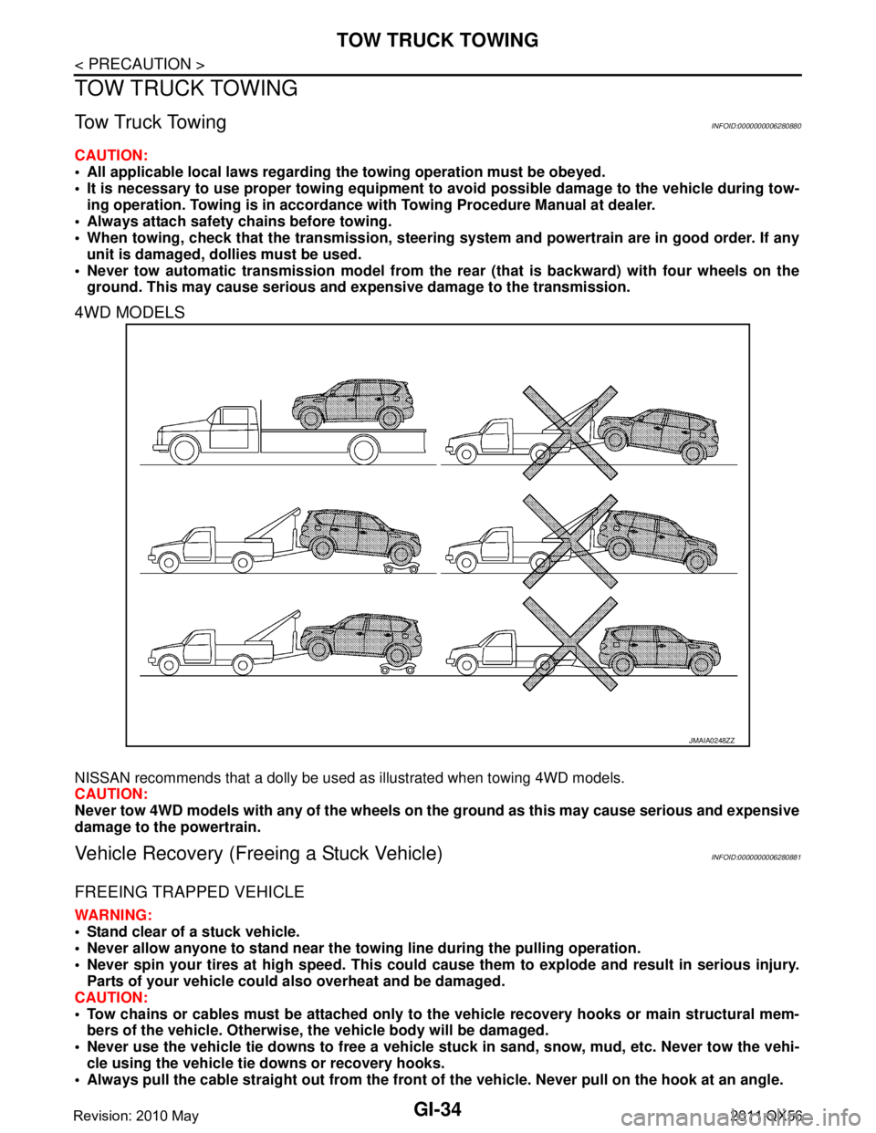
4WD MODELS
NISSAN recommends that a dolly be used as illustrated when towing 4WD models.
CAUTION:
Never tow 4WD models with any of the wheels on the ground as this may cause serious and expensive
damage to the powertrain.
Vehicle Recovery (Freeing a Stuck Vehicle)INFOID:0000000006280881
FREEING TRAPPED VEHICLE
WARNING:
Stand clear of a stuck vehicle.
Never allow anyone to stand near the towing line during the pulling operation.
Never spin your tires at high sp eed. This could cause them to explode and result in serious injury.
Parts of your vehicle could also overheat and be damaged.
CAUTION:
Tow chains or cables must be attached only to the vehicle recovery hooks or main structural mem-
bers of the vehicle. Otherwise, the vehicle body will be damaged.
Never use the vehicle tie downs to free a vehicle st uck in sand, snow, mud, etc. Never tow the vehi-
cle using the vehicle tie downs or recovery hooks.
Always pull the cable straight out from the front of the vehicle. Never pull on the hook at an angle.
JMAIA0248ZZ
Revision: 2010 May2011 QX56
Page 2999 of 5598

TOW TRUCK TOWINGGI-35
< PRECAUTION >
C
DE
F
G H
I
J
K L
M B
GI
N
O P
Pulling devices should be routed so they do not touch any part of the suspension, steering, brake or
cooling systems.
Pulling devices such as ropes or canvas straps ar e not recommended for use in vehicle towing or
recovery.
In order to not break the towi ng line, tension it slowly.
FRONT
REAR
AUTOMATIC TRANSMISSION
To tow a vehicle equipped with an automatic tr ansmission, an appropriate vehicle dolly MUST be placed under
the towed vehicle's drive wheels. Always follow the dolly manufacture's recommendations when using their
product.
If the vehicle is stuck in sand, snow , mud, etc., use the following procedure:
1. Turn off the Vehicle Dynam ic Control System. (if equipped)
2. Check the area in front and behind the vehicle is clear of obstructions.
3. Turn the steering wheel right and left to clear an area around the front tires.
4. Slowly rock the vehicle forward and backward. Shift back and forth between R (reverse) and D (drive).
Apply the accelerator as little as possible to maintain the rocking motion.
Release the accelerator pedal before shifting between R and D.
Do not spin the tires above 35 mph. (55 km/h).
5. If the vehicle can not be freed after a few tries, cont act a professional towing service to remove the vehi-
cle.
JMAIA0254ZZ
JMAIA0255ZZ
Revision: 2010 May2011 QX56