oil type INFINITI QX56 2011 Factory Workshop Manual
[x] Cancel search | Manufacturer: INFINITI, Model Year: 2011, Model line: QX56, Model: INFINITI QX56 2011Pages: 5598, PDF Size: 94.53 MB
Page 3689 of 5598

ENGINE MAINTENANCEMA-19
< PERIODIC MAINTENANCE >
C
DE
F
G H
I
J
K L
M B
MA
N
O A
SPARK PLUG : Removal and InstallationINFOID:0000000006394839
REMOVAL
1. Remove engine cover. Refer to
EM-25, "Exploded View".
2. Remove ignition coil. Refer to EM-29, "
Exploded View".
3. Remove spark plug with a spark plug wrench (commercial ser- vice tool).
INSTALLATION
Note the following item, installa is the reverse order of removal.
CAUTION:
Install ignition coil marked wi th an identification mark (A) on
cylinder No. 5, 6, 7 and 8.
SPARK PLUG : InspectionINFOID:0000000006394840
INSPECTION AFTER REMOVAL
Use the standard type spark plug for normal condition.
CAUTION:
Never drop or impact spark plug.
Never use a wire brush for cleaning.
If plug tip is covered with carbon, use spark plug cleaner to
clean.
Measure spark plug gap. When it exceeds the limit, replace spark plug even if it is within the speci-
fied replacement mileage. Refer to EM-132, "
Spark Plug".
a : 14 mm (0.55 in)
JPBIA0030ZZ
: Engine front
JPBIA3471ZZ
Spark plug (Standard type) : Refer to EM-132, "Spark Plug".
Cleaner air pressure : Less than 588 kPa (5.9 bar, 6 kg/cm
2, 85 psi)
Cleaning time
: Less than 20 seconds
SMA773C
Revision: 2010 May2011 QX56
Page 3696 of 5598
MA-26
< PERIODIC MAINTENANCE >
CHASSIS MAINTENANCE
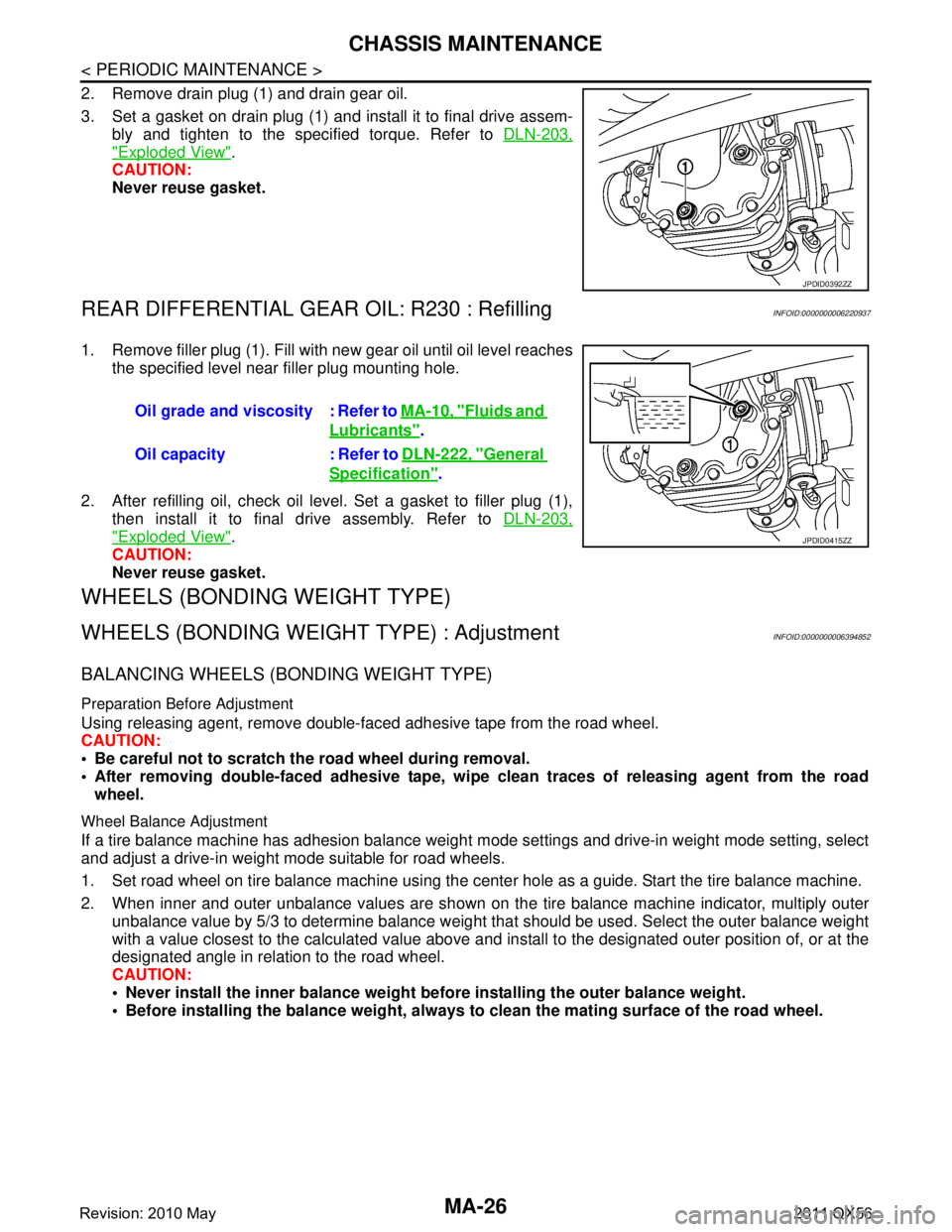
2. Remove drain plug (1) and drain gear oil.
3. Set a gasket on drain plug (1) and install it to final drive assem-bly and tighten to the specified torque. Refer to DLN-203,
"Exploded View".
CAUTION:
Never reuse gasket.
REAR DIFFERENTIAL GEAR OIL: R230 : RefillingINFOID:0000000006220937
1. Remove filler plug (1). Fill with new gear oil until oil level reaches
the specified level near filler plug mounting hole.
2. After refilling oil, check oil level. Set a gasket to filler plug (1), then install it to final drive assembly. Refer to DLN-203,
"Exploded View".
CAUTION:
Never reuse gasket.
WHEELS (BONDING WEIGHT TYPE)
WHEELS (BONDING WEIG HT TYPE) : AdjustmentINFOID:0000000006394852
BALANCING WHEELS (BONDING WEIGHT TYPE)
Preparation Before Adjustment
Using releasing agent, remove double-faced adhesive tape from the road wheel.
CAUTION:
Be careful not to scratch th e road wheel during removal.
After removing double-faced adhesive tape, wi pe clean traces of releasing agent from the road
wheel.
Wheel Balance Adjustment
If a tire balance machine has adhesion balance weight m ode settings and drive-in weight mode setting, select
and adjust a drive-in weight mode suitable for road wheels.
1. Set road wheel on tire balance machine using the center hole as a guide. Start the tire balance machine.
2. When inner and outer unbalance values are shown on the tire balance machine indicator, multiply outer unbalance value by 5/3 to determine balance weight t hat should be used. Select the outer balance weight
with a value closest to the calculated value above and in stall to the designated outer position of, or at the
designated angle in relation to the road wheel.
CAUTION:
Never install the inner balance weight be fore installing the outer balance weight.
Before installing the balance weight, always to clean the mating surface of the road wheel.
JPDID0392ZZ
Oil grade and viscosity : Refer to MA-10, "Fluids and
Lubricants".
Oil capacity : Refer to DLN-222, "
General
Specification".
JPDID0415ZZ
Revision: 2010 May2011 QX56
Page 3705 of 5598

SERVICE DATA AND SPECIFICATIONS (SDS)
MA-35
< SERVICE DATA AND SPECIFICATIONS (SDS)
C
D E
F
G H
I
J
K L
M B
MA
N
O A
SERVICE DATA AND SPECIFICATIONS (SDS)
SERVICE DATA AND SPECIFICATIONS (SDS)
DRIVE BELTS
DRIVE BELTS : Drive BeltsINFOID:0000000006394853
DRIVE BELT
ENGINE COOLANT
ENGINE COOLANT : Periodical Maintenance SpecificationINFOID:0000000006394856
ENGINE COOLANT CAPACITY (APPROXIMATELY)
Unit: (US qt, Imp qt)
ENGINE OIL
ENGINE OIL : Periodical Maintenance SpecificationINFOID:0000000006394855
ENGINE OIL CAPACITY (APPROXIMATE)
Unit: (US qt, Imp qt)
SPARK PLUG
SPARK PLUG : Spark PlugINFOID:0000000006394854
SPARK PLUG
Unit: mm (in)
ROAD WHEEL
ROAD WHEEL : Road WheelINFOID:0000000006349771
ALUMINUM WHEEL
Tension of drive belts Belt tension is not necessary, as it is automatically adjusted by drive belt auto-tensioner.
Engine coolant capacity [With reservoir tank (“MAX” level)] 14.9 (15-6/8, 13-1/8)
Reservoir tank engine coolant capacity (At “MAX” level) 1.0 (1, 7/8)
Drain and refill
With oil filter change 6.5 (6-7/8, 5-3/4)
Without oil filter change 6.2 (6-4/8, 5-1/2)
Dry engine (engine overhaul) 7.6 (8, 6-3/4)
Make NGK
Standard type DILKAR7B11
Gap Standard 1.1 (0.043)
Limit 1.25 (0.049)
Item Limit
Radial runout Lateral deflection
Less than 0.3 mm (0.012 in)
Vertical deflection
Allowable unbalance Dynamic (At flange) Less than 7 g (0.25 oz) (one side)
Static (At flange) Less than 14 g (0.49 oz)
Revision: 2010 May2011 QX56
Page 4300 of 5598

PRECAUTIONSSBC-3
< PRECAUTION >
C
DE
F
G
I
J
K L
M A
B
SBC
N
O P
PRECAUTION
PRECAUTIONS
Precaution for Supplemental Restraint System (SRS) "AIR BAG" and "SEAT BELT
PRE-TENSIONER"
INFOID:0000000006237873
The Supplemental Restraint System such as “A IR BAG” and “SEAT BELT PRE-TENSIONER”, used along
with a front seat belt, helps to reduce the risk or severi ty of injury to the driver and front passenger for certain
types of collision. This system includes seat belt switch inputs and dual stage front air bag modules. The SRS
system uses the seat belt switches to determine the front air bag deployment, and may only deploy one front
air bag, depending on the severity of a collision and whether the front occupants are belted or unbelted.
Information necessary to service the system safely is included in the “SRS AIR BAG” and “SEAT BELT” of this
Service Manual.
WARNING:
• To avoid rendering the SRS inoper ative, which could increase the risk of personal injury or death in
the event of a collision that would result in air ba g inflation, all maintenance must be performed by
an authorized NISSAN/INFINITI dealer.
Improper maintenance, including in correct removal and installation of the SRS, can lead to personal
injury caused by unintentional act ivation of the system. For removal of Spiral Cable and Air Bag
Module, see the “SRS AIR BAG”.
Do not use electrical test equipm ent on any circuit related to the SRS unless instructed to in this
Service Manual. SRS wiring harnesses can be identi fied by yellow and/or orange harnesses or har-
ness connectors.
PRECAUTIONS WHEN USING POWER TOOLS (AIR OR ELECTRIC) AND HAMMERS
WARNING:
When working near the Air Bag Diagnosis Sensor Unit or other Air Bag System sensors with the
ignition ON or engine running, DO NOT use air or electric power tools or strike near the sensor(s)
with a hammer. Heavy vibration could activate the sensor(s) and deploy the air bag(s), possibly
causing serious injury.
When using air or electric power tools or hammers , always switch the ignition OFF, disconnect the
battery, and wait at least 3 minutes before performing any service.
Precaution for Seat Belt ServiceINFOID:0000000006237874
CAUTION:
Before removing the seat belt pre-tensioner assembly, turn the ignition switch off, disconnect the
both battery cables and wait at least 3 minutes.
Do not use electrical test equipment for seat belt pre-tensioner connector.
After replacing or reinstalling seat belt pre-tens ioner assembly, or reconnecting front seat belt pre-
tensioner connector, check the system function. Refer to SRC-11, "
System Diagram".
Do not use disassemble buckle or seat belt assembly.
Replace anchor bolts if th ey are deformed or worn out.
Never oil tongue and buckle.
If any component of seat belt assembly is questio nable, do not repair. Replace the whole seat belt
assembly.
If webbing is cut, frayed, or damaged, replace seat belt assembly.
When replacing seat belt assembly, u se a genuine NISSAN seat belt assembly.
AFTER A COLLISION
WARNING:
Inspect all seat belt assemblies including retractors and attaching hardware after any collision.
NISSAN recommends that all seat belt assemblies in u se during a collision be replaced unless the col-
lision was minor and the belts show no damage a nd continue to operate properly. Failure to do so
could result in serious personal injury in an accide nt. Seat belt assemblies not in use during a colli-
sion should also be replaced if either damage or im proper operation is noted. Seat belt pre-tensioner
should be replaced even if the seat belts are not in use during a frontal collision in which the air bags
are deployed.
Replace any seat belt assembly (including anchor bolts) if:
Revision: 2010 May2011 QX56
Page 4463 of 5598

SE-4
< PRECAUTION >
PRECAUTIONS
PRECAUTION
PRECAUTIONS
Precaution for Supplemental Restraint System (SRS) "AIR BAG" and "SEAT BELT
PRE-TENSIONER"
INFOID:0000000006237842
The Supplemental Restraint System such as “A IR BAG” and “SEAT BELT PRE-TENSIONER”, used along
with a front seat belt, helps to reduce the risk or severi ty of injury to the driver and front passenger for certain
types of collision. This system includes seat belt switch inputs and dual stage front air bag modules. The SRS
system uses the seat belt switches to determine the front air bag deployment, and may only deploy one front
air bag, depending on the severity of a collision and w hether the front occupants are belted or unbelted.
Information necessary to service the system safely is included in the “SRS AIR BAG” and “SEAT BELT” of this
Service Manual.
WARNING:
• To avoid rendering the SRS inopera tive, which could increase the risk of personal injury or death in
the event of a collision that would result in air bag inflation, all maintenance must be performed by
an authorized NISS AN/INFINITI dealer.
Improper maintenance, including in correct removal and installation of the SRS, can lead to personal
injury caused by unintent ional activation of the system. For re moval of Spiral Cable and Air Bag
Module, see the “SRS AIR BAG”.
Do not use electrical test equipmen t on any circuit related to the SRS unless instructed to in this
Service Manual. SRS wiring harnesses can be identi fied by yellow and/or orange harnesses or har-
ness connectors.
PRECAUTIONS WHEN USING POWER TOOLS (AIR OR ELECTRIC) AND HAMMERS
WARNING:
When working near the Air Bag Diagnosis Sensor Unit or other Air Bag System sensors with the ignition ON or engine running, DO NOT use air or electric power tools or strike near the sensor(s)
with a hammer. Heavy vibration could activate the sensor(s) and deploy the air bag(s), possibly
causing serious injury.
When using air or electric power tools or hammers , always switch the ignition OFF, disconnect the
battery, and wait at least 3 minu tes before performing any service.
Service NoticeINFOID:0000000006217352
When removing or installing various parts, place a cloth or padding onto the vehicle body to prevent
scratches.
Handle trim, molding, instruments, grille, etc. carefull y during removing or installing. Be careful not to oil or
damage them.
Apply sealing compound where necessary when installing parts.
When applying sealing compound, be careful that t he sealing compound never protrudes from parts.
When replacing any metal parts (for example body outer panel, members, etc.), always take rust prevention
measures.
Precaution for WorkINFOID:0000000006217353
When removing or disassembling each component, be careful not to damage or deform it. If a component
may be subject to interference, al ways protect it with a shop cloth.
When removing (disengaging) components with a screwdriver or similar tool, always wrap the component
with a shop cloth or vinyl tape to protect it.
Protect the removed parts with a shop cloth and keep them.
Replace a deformed or damaged clip.
If a part is specified as a non-reusable part, always replace it with new one.
Always tighten bolts and nuts securely to the specified torque.
After reinstallation is complete, always check that each part works normally.
Follow the steps below to clean components.
- Water soluble foul: Dip a soft cloth into lukewarm water, and wring the water out of the cloth to wipe the fouled area.
Then rub with a soft and dry cloth.
Revision: 2010 May2011 QX56
Page 4799 of 5598

SRC-6
< PRECAUTION >
PRECAUTIONS
PRECAUTION
PRECAUTIONS
Precaution for Supplemental Restraint System (SRS) "AIR BAG" and "SEAT BELT
PRE-TENSIONER"
INFOID:0000000006219946
The Supplemental Restraint System such as “A IR BAG” and “SEAT BELT PRE-TENSIONER”, used along
with a front seat belt, helps to reduce the risk or severi ty of injury to the driver and front passenger for certain
types of collision. This system includes seat belt switch inputs and dual stage front air bag modules. The SRS
system uses the seat belt switches to determine the front air bag deployment, and may only deploy one front
air bag, depending on the severity of a collision and w hether the front occupants are belted or unbelted.
Information necessary to service the system safely is included in the “SRS AIR BAG” and “SEAT BELT” of this
Service Manual.
WARNING:
• To avoid rendering the SRS inopera tive, which could increase the risk of personal injury or death in
the event of a collision that would result in air bag inflation, all maintenance must be performed by
an authorized NISS AN/INFINITI dealer.
Improper maintenance, including in correct removal and installation of the SRS, can lead to personal
injury caused by unintent ional activation of the system. For re moval of Spiral Cable and Air Bag
Module, see the “SRS AIR BAG”.
Do not use electrical test equipmen t on any circuit related to the SRS unless instructed to in this
Service Manual. SRS wiring harnesses can be identi fied by yellow and/or orange harnesses or har-
ness connectors.
PRECAUTIONS WHEN USING POWER TOOLS (AIR OR ELECTRIC) AND HAMMERS
WARNING:
When working near the Air Bag Diagnosis Sensor Unit or other Air Bag System sensors with the ignition ON or engine running, DO NOT use air or electric power tools or strike near the sensor(s)
with a hammer. Heavy vibration could activate the sensor(s) and deploy the air bag(s), possibly
causing serious injury.
When using air or electric power tools or hammers , always switch the ignition OFF, disconnect the
battery, and wait at least 3 minu tes before performing any service.
ServiceINFOID:0000000006219947
Never use electrical test equipment to check SRS circuits unless instructed to in this Service Manual.
Before servicing the SRS, turn ignition switch OF F, disconnect battery negative terminal and wait 3 minutes
or more.
For approximately 3 minutes after the cables are removed, it is still possible for the air bag and seat belt pre-
tensioner to deploy. Therefore, never work on any SR S connectors or wires until at least 3 minutes have
passed.
Diagnosis sensor unit must always be installed with their arrow marks “ ⇐” pointing towards the front of the
vehicle for proper operation. Also chec k diagnosis sensor unit for cracks, deformities or rust before installa-
tion and replace as required.
The spiral cable must be aligned with the neutral position since its rotations are limited. Never turn steering
wheel and column after removal of steering gear.
Handle air bag module carefully. Always place driver and front passenger air bag modules with the pad side facing upward and seat mounted front side air bag module standing with the stud bolt side facing down.
Conduct self-diagnosis to check entire SRS for proper function after replacing any components.
After air bag inflates, the front instrument panel assembly should be replaced if damaged.
Always replace instrument panel pad following front passenger air bag deployment.
Never solder the harness when making repairs. Check that harness is not pinched and that there is no con-
tact with other components.
Never allow harness to come in contact with oil, grease, waste oil, or water.
Never insert foreign materials, such as a screwdriver , into the harness connector. (This is to prevent acci-
dental activation caused by static electricity.)
Always use CONSULT-III or SRS air bag warning lamp to perform the circuit diagnosis. (Never use an elec- tric tester such as a circuit tester.)
Never enter in the deployment area of the pop-up roll bar. Never put an object in the deployment area of the
pop-up roll bar. (This is to prevent injury in case of an unintentional deployment.)
Revision: 2010 May2011 QX56
Page 5041 of 5598

ST-54
< REMOVAL AND INSTALLATION >
HYDRAULIC LINE
HYDRAULIC LINE
Exploded ViewINFOID:0000000006225615
Engine speed sensitive type
JPGIA0096GB
1. Reservoir tank bracket 2. Reservoir tank 3. Clamp
4. Suction hose 5. Return hose 6. Eye bolt
7. Copper washer 8. Pressure sensor 9. Oil cooler
10. High pressure piping 11. Low pressure piping 12. Steering gear assembly
A. To power steering oil pump suction hose.
B. To power steering oil pump.
Refer to GI-4, "
Components" for symbols in the figure.
Revision: 2010 May2011 QX56
Page 5042 of 5598

HYDRAULIC LINEST-55
< REMOVAL AND INSTALLATION >
C
DE
F
H I
J
K L
M A
B
ST
N
O P
Vehicle speed sensitive type
JPGIA0074GB
1. Reservoir tank bracket 2. Reservoir tank 3. Clamp
4. Suction hose 5. Return hose 6. Eye bolt
7. Copper washer 8. Pressure sensor 9. Oil cooler
10. High pressure piping 11. Low pressure piping 12. Steering gear assembly
A. To power steering oil pump suction hose.
B. To power steering oil pump.
Refer to GI-4, "
Components" for symbols in the figure.
Revision: 2010 May2011 QX56
Page 5094 of 5598
![INFINITI QX56 2011 Factory Workshop Manual
TM-6
< PRECAUTION >[7AT: RE7R01B]
PRECAUTIONS
PRECAUTION
PRECAUTIONS
Precaution for Supplemental Restraint S
ystem (SRS) "AIR BAG" and "SEAT BELT
PRE-TENSIONER"
INFOID:0000000006226734
The Supplemen](/img/42/57033/w960_57033-5093.png "INFINITI QX56 2011 Factory Workshop Manual
TM-6
< PRECAUTION >[7AT: RE7R01B]
PRECAUTIONS
PRECAUTION
PRECAUTIONS
Precaution for Supplemental Restraint S
ystem (SRS) \"AIR BAG\" and \"SEAT BELT
PRE-TENSIONER\"
INFOID:0000000006226734
The Supplemen")
TM-6
< PRECAUTION >[7AT: RE7R01B]
PRECAUTIONS
PRECAUTION
PRECAUTIONS
Precaution for Supplemental Restraint S
ystem (SRS) "AIR BAG" and "SEAT BELT
PRE-TENSIONER"
INFOID:0000000006226734
The Supplemental Restraint System such as “A IR BAG” and “SEAT BELT PRE-TENSIONER”, used along
with a front seat belt, helps to reduce the risk or severi ty of injury to the driver and front passenger for certain
types of collision. This system includes seat belt switch inputs and dual stage front air bag modules. The SRS
system uses the seat belt switches to determine the front air bag deployment, and may only deploy one front
air bag, depending on the severity of a collision and w hether the front occupants are belted or unbelted.
Information necessary to service the system safely is included in the “SRS AIR BAG” and “SEAT BELT” of this
Service Manual.
WARNING:
• To avoid rendering the SRS inopera tive, which could increase the risk of personal injury or death in
the event of a collision that would result in air bag inflation, all maintenance must be performed by
an authorized NISS AN/INFINITI dealer.
Improper maintenance, including in correct removal and installation of the SRS, can lead to personal
injury caused by unintent ional activation of the system. For re moval of Spiral Cable and Air Bag
Module, see the “SRS AIR BAG”.
Do not use electrical test equipmen t on any circuit related to the SRS unless instructed to in this
Service Manual. SRS wiring harnesses can be identi fied by yellow and/or orange harnesses or har-
ness connectors.
PRECAUTIONS WHEN USING POWER TOOLS (AIR OR ELECTRIC) AND HAMMERS
WARNING:
When working near the Air Bag Diagnosis Sensor Unit or other Air Bag System sensors with the ignition ON or engine running, DO NOT use air or electric power tools or strike near the sensor(s)
with a hammer. Heavy vibration could activate the sensor(s) and deploy the air bag(s), possibly
causing serious injury.
When using air or electric power tools or hammers , always switch the ignition OFF, disconnect the
battery, and wait at least 3 minu tes before performing any service.
General PrecautionsINFOID:0000000006226735
Turn ignition switch OFF an d disconnect the battery cable
from the negative terminal before connecting or disconnect-
ing the A/T assembly connector. Because battery voltage is
applied to TCM even if igniti on switch is turned OFF.
Perform “DTC (Diagnostic Trouble Code) CONFIRMATION
PROCEDURE” after performing each TROUBLE DIAGNOSIS.
If the repair is completed DTC should not be displayed in the
“DTC CONFIRMATION PROCEDURE”.
Always use the specified brand of ATF. Refer to MA-10, "
Fluids
and Lubricants".
Use lint-free paper not cloth rags during work.
Dispose of the waste oil using the methods prescribed by law, ordi-
nance, etc. after replacing the ATF.
Before proceeding with disassembly, thoroughly clean the outside of the transmission. It is important to prevent the internal parts from
becoming contaminated by dirt or other foreign matter.
SEF289H
SEF217U
Revision: 2010 May2011 QX56
Page 5101 of 5598
![INFINITI QX56 2011 Factory Workshop Manual
COMPONENT PARTSTM-13
< SYSTEM DESCRIPTION > [7AT: RE7R01B]
C
EF
G H
I
J
K L
M A
B
TM
N
O P
A/T CONTROL SYSTEM : High and Lo w Reverse Clutch Solenoid ValveINFOID:0000000006226748
The high and low r](/img/42/57033/w960_57033-5100.png "INFINITI QX56 2011 Factory Workshop Manual
COMPONENT PARTSTM-13
< SYSTEM DESCRIPTION > [7AT: RE7R01B]
C
EF
G H
I
J
K L
M A
B
TM
N
O P
A/T CONTROL SYSTEM : High and Lo w Reverse Clutch Solenoid ValveINFOID:0000000006226748
The high and low r")
COMPONENT PARTSTM-13
< SYSTEM DESCRIPTION > [7AT: RE7R01B]
C
EF
G H
I
J
K L
M A
B
TM
N
O P
A/T CONTROL SYSTEM : High and Lo w Reverse Clutch Solenoid ValveINFOID:0000000006226748
The high and low reverse clutch solenoid valve is controlled by the TCM in response to signals transmitted
from the transmission range switch, output speed sens or and accelerator pedal position sensor. Gears will
then be shifted to the optimum position.
The high and low reverse clutch solenoid valve controls the high and low reverse clutch control valve in response to a signal transmitted from the TCM.
A/T CONTROL SYSTEM : Lo w Brake Solenoid ValveINFOID:0000000006226749
The low brake solenoid valve is controlled by the TC M in response to signals transmitted from the transmis-
sion range switch, output speed sensor and accelerator pedal position sensor. Gears will then be shifted to
the optimum position.
The low brake solenoid valve controls the low brake control valve in response to a signal transmitted from
the TCM.
A/T CONTROL SYSTEM : Anti-interlock Solenoid ValveINFOID:0000000006226750
Anti-interlock solenoid valve prevents the simultaneous activation of the input clutch and the low brake.
The anti-interlock solenoid valve is an ON/OFF type solenoid valve.
A/T CONTROL SYSTEM : 2 346 Brake Solenoid ValveINFOID:0000000006226751
The 2346 brake solenoid valve is controlled by the TC M in response to signals transmitted from the trans-
mission range switch, output speed sensor and accelera tor pedal position sensor. Gears will then be shifted
to the optimum position.
The 2346 brake solenoid valve controls the 2346 brake c ontrol valve in response to a signal transmitted from
the TCM.
A/T CONTROL SYSTEM : Torque Co nverter Clutch Solenoid ValveINFOID:0000000006226752
The torque converter clutch solenoid va lve is activated, with the gear in D2, D3, D4, D5, D6, D7, M2, M3, M4,
M5, M6 and M7 by the TCM in response to signals tr ansmitted from the output speed sensor and accelerator
pedal position sensor. Torque converter clut ch piston operation will then be controlled.
A/T CONTROL SYSTEM : Line Pressure Solenoid ValveINFOID:0000000006226753
The line pressure solenoid valve regulates the oil pum p discharge pressure to suit the driving condition in
response to a signal transmitted from the TCM.
A/T CONTROL SYSTEM : Accele rator Pedal Position SensorINFOID:0000000006226754
The accelerator pedal position sensor is installed on the upper end of the accelerator pedal assembly.
The accelerator pedal position sensor detects the accelerator position.
The accelerator pedal position sensor transform the a ccelerator pedal position into output voltage, and emit
the voltage signal to the ECM. Then, the TCM receives accelerator pedal position signal from the ECM via
CAN communication.
A/T CONTROL SYSTEM : Manual Mode SwitchINFOID:0000000006226755
The manual mode switch [mode select switch and position se lect switch (shift-up/shift-down)] is installed in
the A/T shift selector assembly.
The mode select switch detects the position (the main shift gate side or manual shift gate side) of the selec-
tor lever and transmits a manual mode signal or a not manual mode signal to the combination meter. Then,
the TCM receives a manual mode signal or non-manual mode signal from the combination meter.
The position select switch (shift-up) detects that the se lector lever is shifted to the shift-up side of the manual
shift gate and transmits a manual mode shift up signal to the combination meter. Then, the TCM receives a
manual mode shift up signal from the combination meter.
The position select switch (shift-down) detects that the selector lever is shifted to the shift-down side of the
manual shift gate and transmits a manual mode shift down signal to the combination meter. Then, the TCM
receives a manual mode shift down signal from the combination meter.
Revision: 2010 May2011 QX56