key INFINITI QX56 2011 Factory Service Manual
[x] Cancel search | Manufacturer: INFINITI, Model Year: 2011, Model line: QX56, Model: INFINITI QX56 2011Pages: 5598, PDF Size: 94.53 MB
Page 10 of 5598
ADP-1
BODY INTERIOR
C
DE
F
G H
I
K L
M
SECTION ADP
A
B
ADP
N
O P
CONTENTS
AUTOMATIC DRIVE POSITIONER
PRECAUTION ................ ...............................5
PRECAUTIONS .............................................. .....5
Precaution for Supplemental Restraint System
(SRS) "AIR BAG" and "SEAT BELT PRE-TEN-
SIONER" ............................................................. ......
5
SYSTEM DESCRIPTION ..............................6
COMPONENT PARTS ................................... .....6
Component Parts Location .................................. ......6
Component Description ............................................7
SYSTEM .............................................................11
AUTOMATIC DRIVE POSITIONER SYSTEM ....... ....11
AUTOMATIC DRIVE POSITIONER SYSTEM :
System Diagram ......................................................
11
AUTOMATIC DRIVE POSITIONER SYSTEM :
System Description .................................................
11
MANUAL FUNCTION ............................................ ....12
MANUAL FUNCTION : System Diagram ................13
MANUAL FUNCTION : System Description ............13
MEMORY FUNCTION ........................................... ....14
MEMORY FUNCTION : System Diagram ...............15
MEMORY FUNCTION : System Description ..........15
EXIT ASSIST FUNCTION ...................................... ....17
EXIT ASSIST FUNCTION : System Diagram .........17
EXIT ASSIST FUNCTION : Sy stem Description .....17
ENTRY ASSIST FUNCTION ................................. ....18
ENTRY ASSIST FUNCTION : System Diagram .....18
ENTRY ASSIST FUNCTION : System Description
....
18
INTELLIGENT KEY INTERLOCK FUNCTION ...... ....19
INTELLIGENT KEY INTERLOCK FUNCTION :
System Diagram ......................................................
20
INTELLIGENT KEY INTERLOCK FUNCTION :
System Description .................................................
20
Fail Safe .............................................................. ....21
DIAGNOSIS SYSTEM (DRIVER SEAT CON-
TROL UNIT) ......................................................
22
CONSULT-III Function ............................................22
ECU DIAGNOSIS INFORMATION ..............25
DRIVER SEAT CONTROL UNIT ......................25
Reference Value .................................................. ....25
Fail Safe ..................................................................30
DTC Index ...............................................................31
AUTOMATIC DRIVE POSITIONER CON-
TROL UNIT ........................................................
32
Reference Value ......................................................32
BCM (BODY CONTROL MODULE) .................35
List of ECU Reference .............................................35
WIRING DIAGRAM ......................................36
AUTOMATIC DRIVE POSITIONER SYSTEM ...36
Wiring Diagram .................................................... ....36
BASIC INSPECTION ...................................48
DIAGNOSIS AND REPAIR WORK FLOW .......48
Work Flow ............................................................ ....48
INSPECTION AND ADJUSTMENT ..................51
ADDITIONAL SERVICE WHEN REMOVING BAT-
TERY NEGATIVE TERMINAL ............................... ....
51
ADDITIONAL SERVICE WHEN REMOVING
BATTERY NEGATIVE TERMINAL : Description .....
51
ADDITIONAL SERVICE WHEN REMOVING
BATTERY NEGATIVE TERMINAL : Special Re-
pair Requirement .....................................................
51
ADDITIONAL SERVICE WHEN REPLACING
CONTROL UNIT .................................................... ....
51
Revision: 2010 May2011 QX56
Page 11 of 5598

ADP-2
ADDITIONAL SERVICE WHEN REPLACING
CONTROL UNIT : Description ................................
51
ADDITIONAL SERVICE WHEN REPLACING
CONTROL UNIT : Special Repair Requirement .....
52
SYSTEM INITIALIZATION . .......................................52
SYSTEM INITIALIZATION : Description .................52
SYSTEM INITIALIZATION : Special Repair Re-
quirement ............................................................. ...
52
MEMORY STORING .............................................. ...53
MEMORY STORING : Description .........................53
MEMORY STORING : Special Repair Require-
ment ........................................................................
53
INTELLIGENT KEY INTERLOCK STORING ........ ...53
INTELLIGENT KEY INTERLOCK STORING : De-
scription ..................................................................
54
INTELLIGENT KEY INTERLOCK STORING :
Special Repair Requirement ...................................
54
SYSTEM SETTING ...................................................54
SYSTEM SETTING : Descrip tion ...........................54
SYSTEM SETTING : Specia l Repair Requirement
...
55
DTC/CIRCUIT DIAGNOSIS ...................... ...56
U1000 CAN COMM CIRCUIT ......................... ...56
Description ........................................................... ...56
DTC Logic ...............................................................56
Diagnosis Procedure .............................................56
Special Repair Requirement ...................................56
U1010 CONTROL UNIT (CAN) .........................57
DTC Logic ............................................................ ...57
Diagnosis Procedure ..............................................57
B2112 SLIDING MOTOR ...................................58
DTC Logic ............................................................ ...58
Diagnosis Procedure .............................................58
B2113 RECLINING MOTOR ..............................60
DTC Logic ............................................................ ...60
Diagnosis Procedure .............................................60
B2116 TILT MOTOR ..........................................62
DTC Logic ............................................................ ...62
Diagnosis Procedure .............................................62
B2128 UART COMMUNICATION LINE ............64
Description ........................................................... ...64
DTC Logic ...............................................................64
Diagnosis Procedure .............................................64
B2130 EEPROM ................................................66
DTC Logic ............................................................ ...66
Diagnosis Procedure .............................................66
POWER SUPPLY AND GROUND CIRCUIT .....67
DRIVER SEAT CONTROL UNIT ........................... ...67
DRIVER SEAT CONTROL UNIT :
Diagnosis Procedure ..............................................
67
DRIVER SEAT CONTROL UNIT : Special Repair
Requirement ...........................................................
67
AUTOMATIC DRIVE POSITIONER CONTROL
UNIT ........................................................................ ...
67
AUTOMATIC DRIVE POSITIONER CONTROL
UNIT : Diagnosis Procedure ..................................
67
AUTOMATIC DRIVE POSITIONER CONTROL
UNIT : Special Repair Requirement ........................
68
SLIDING SWITCH .............................................69
Component Function Check ............................... ...69
Diagnosis Procedure ..............................................69
Component Inspection ............................................70
RECLINING SWITCH ........................................71
Component Function Check ............................... ...71
Diagnosis Procedure ..............................................71
Component Inspection ............................................72
LIFTING SWITCH (FRONT) ..............................73
Component Function Check ............................... ...73
Diagnosis Procedure ..............................................73
Component Inspection ............................................74
LIFTING SWITCH (REAR) ................................75
Component Function Check ............................... ...75
Diagnosis Procedure ..............................................75
Component Inspection ............................................76
TILT SWITCH ....................................................77
Component Function Check ............................... ...77
Diagnosis Procedure ..............................................77
Component Inspection ............................................78
TELESCOPIC SWITCH .....................................79
Component Function Check ............................... ...79
Diagnosis Procedure ..............................................79
Component Inspection ............................................80
SEAT MEMORY SWITCH .................................81
Component Function Check ............................... ...81
Diagnosis Procedure ..............................................81
Component Inspection ............................................82
DOOR MIRROR REMOTE CONTROL
SWITCH .............................................................
83
CHANGEOVER SWITCH ....................................... ...83
CHANGEOVER SWITCH : Component Function
Check ......................................................................
83
CHANGEOVER SWITCH : Diagnosis Procedure ...83
CHANGEOVER SWITCH : Component Inspec-
tion ..........................................................................
84
MIRROR SWITCH .................................................. ...84
MIRROR SWITCH : Component Function Check ...84
MIRROR SWITCH : Diagnosis Procedure ..............85
MIRROR SWITCH : Component Inspection ...........86
Revision: 2010 May2011 QX56
Page 13 of 5598

ADP-4
STEERING TELESCOPIC .......................................129
STEERING TELESCOPIC : Diagnosis Procedure ..129
DOOR MIRROR ..................................................... ..130
DOOR MIRROR : Diagnosis Procedure ................130
ENTRY/EXIT ASSIST FUNCTION DOES NOT
OPERATE ........................................................
131
Diagnosis Procedure ........................................... ..131
INTELLIGENT KEY INTERLOCK FUNCTION
DOES NOT OPERATE ....................................
132
Diagnosis Procedure ........................................... ..132
MEMORY INDICATE DOES NOT OPERATE .133
Diagnosis Procedure .............................................133
NORMAL OPERATING CONDITION ..............134
Description ........................................................... ..134
REMOVAL AND INSTALLATION .............135
DRIVER SEAT CONTROL UNIT .................... ..135
Removal and Installation ...................................... .135
AUTOMATIC DRIVE POSITIONER CON-
TROL UNIT .......................................................
136
Removal and Installation ...................................... .136
SEAT MEMORY SWITCH ................................137
Removal and Installation ...................................... .137
POWER SEAT SWITCH ...................................138
Removal and Installation ...................................... .138
TILT&TELESCOPIC SWITCH ..........................139
Removal and Installation ...................................... .139
Revision: 2010 May2011 QX56
Page 16 of 5598
COMPONENT PARTSADP-7
< SYSTEM DESCRIPTION >
C
DE
F
G H
I
K L
M A
B
ADP
N
O P
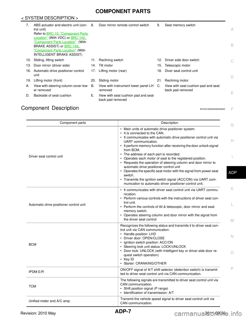
Component DescriptionINFOID:0000000006248302
7. ABS actuator and electric unit (con- trol unit)
Refer to BRC-10, "
Component Parts
Location" (With VDC) or BRC-142,
"Component Parts Location" (With
BRAKE ASSIST) or BRC-149,
"Component Parts Location" (With
INTELLIGENT BRAKE ASSIST) 8. Door mirror remote
control switch 9. Seat memory switch
10. Sliding, lifting switch 11. Reclining switch 12. Driver side door switch
13. Door mirror (driver side) 14. T ilt motor 15. Telescopic motor
16. Automatic drive positioner control unit 17. Lifting motor (rear) 18.
Diver seat control unit
19. Lifting motor (front) 20. Sliding motor 21. Reclining motor
A. View with steering column cover low- er removed B. View with instrument lower panel LH
removed C. View with seat cushion pad and seat
back pad removed
D. Backside of seat cushion E. View with seat cushion pad and seat back pad removed
Component parts Description
Driver seat control unit Main units of automatic drive positioner system.
It is connected to the CAN.
It communicates with automatic drive positioner control unit via
UART communication.
It perform memory function after receiving the door unlock signal
from BCM.
The address of each part is recorded.
Operates each motor of seat to the registered position.
Requests the operation of steering column and door mirror to automatic drive positioner control unit
Operates the specific seat motor with the signal from power seat
switch.
Transmits the ignition switch signal (ACC/ON) via UART com- munication to automatic driver positioner control unit.
Automatic drive positioner control unit It communicates with driver seat control unit via UART commu-
nication.
Perform various controls with the instructions of driver seat con- trol unit.
Perform the controls of tilt & telescopic, door mirror and seat memory switch.
Operates steering column and door mirror with the signal from the driver seat control
BCM Recognizes the following status and transmits it to driver seat con-
trol unit via CAN communication.
Handle position: LHD
Driver door: OPEN/CLOSE
Ignition switch position: ACC/ON
Steering lock unit status: LOCK/UNLOCK
Door lock: UNLOCK (with Intelligent key or driver side door re-
quest switch operation)
Key ID
Starter: CRANKING/OTHER
IPDM E/R ON/OFF signal of A/T shift selector (detention switch) is transmit-
ted to driver seat control unit via CAN communication.
TCM The following signals are transmitted to driver seat control unit via
CAN communication.
Shift position signal (P range)
Identification of transmission: A/T
Unified meter and A/C amp. Transmit the vehicle speed signal to driver seat control unit via
CAN communication.
Revision: 2010 May2011 QX56
Page 17 of 5598

ADP-8
< SYSTEM DESCRIPTION >
COMPONENT PARTS
ABS actuator and electric unit (control unit)Transmit the vehicle speed signal to driver seat control unit via
CAN communication.
A/T sift selector (Detention switch) Detention switch is installed on A/T shift selector. It is turned
OFF when A/T shift selector is in P position.
Driver seat control unit judges that A/T shift selector is in P posi- tion if continuity does not exist in this circuit.
Door mirror remote con-
trol switch Mirror switch
Mirror switch is integrated in
door mirror remote control switch.
It operates angle of door mirror face.
It transmits mirror face adjust operation to automatic drive posi- tioner control unit.
Changeover switch Changeover switch is integrated
in door mirror remote control
switch.
Changeover switch has three positions (L, N and R).
It changes operating door mirror motor by transmitting control signal to automatic drive positioner control unit.
Open/close switch Open/close switch is integrated in door mirror remote control
switch.
Power is supplied to folding mi rror from door mirror remote con-
trol switch when operating switch.
Tilt & telescopic switch Tilt switch
Tilt switch is equipped to steering column.
The operation signal is input to automatic drive positioner control
unit when tilt switch is operated.
Telescopic switch Telescopic switch is equipped to steering column.
The operation signal is input to automatic drive positioner control
unit when telescopic switch is operated.
Seat memory switch Set switch
It is used for registration and setting change of driving position and
Intelligent Key interlock function.
Seat memory switch The maximum 2 driving positions can be registered by memory
switch 1 to 2.
Driving position is set to the registered driving position when memory switch is pressed while operation conditions are satis-
fied.
Seat memory indicator Memory indicator indicates the status of auto driving position sys-
tem by turning ON or blinking.
Power seat switch Sliding switch
Sliding switch is equipped to power seat switch on seat cushion
side surface.
The operation signal is input to driver seat control unit when slid- ing switch is operated.
Reclining switch The operation signal is input to driver seat control unit when re-
clining switch is operated.
The operation signal is input to driver seat control unit when re-
clining switch is operated.
Lifting switch (front) Lifting switch (front) is equipped to power seat switch on seat
cushion side surface.
The operation signal is input to driver seat control unit when lift-
ing switch (front) is operated.
Lifting switch (rear) Lifting switch (rear) is equipped to power seat switch on seat
cushion side surface.
The operation signal is input to driver seat control unit when lift-
ing switch (rear) is operated.
Component parts Description
Revision: 2010 May2011 QX56
Page 21 of 5598
ADP-12
< SYSTEM DESCRIPTION >
SYSTEM
NOTE:
The lumbar support system are controlled independently with no link to the automatic drive positioner system.
Refer to SE-16, "
LUMBAR SUPPORT SYSTEM : System Description".
Sleep control
Driver seat control unit equips sleep control for reducing power consumption.
The system switches to sleep control when al l of the following conditions are satisfied.
Ignition switch is OFF (steering lock status).
All devices of auto driving pos ition system are not operating.
45 seconds timer of driver s eat control unit is not operating.
Set switch and memory switch (1 and 2) are OFF.
Wake-up control
Sleep control releases when detecting status change in either of the following item.
CAN communication
Power seat switch
Set switch and seat memory switch (1 and 2)
Tilt & telescopic switch
MANUAL FUNCTION
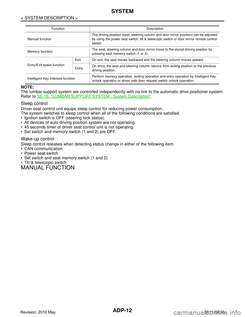
Function Description
Manual function The driving position (seat, steering column and door mirror position) can be adjusted
by using the power seat switch, tilt & telescopic switch or door mirror remote control
switch.
Memory function The seat, steering column and door mirror move to the stored driving position by
pressing seat memory switch (1 or 2).
Entry/Exit assist function Exit On exit, the seat moves backward and the steering column moves upward.
Entry
On entry, the seat and steering column returns from exiting position to the previous
driving position.
Intelligent Key interlock function Perform memory operation, exiting operation and entry operation by Intelligent Key
unlock operation or driver side door request switch unlock operation.
Revision: 2010 May2011 QX56
Page 28 of 5598
SYSTEMADP-19
< SYSTEM DESCRIPTION >
C
DE
F
G H
I
K L
M A
B
ADP
N
O P
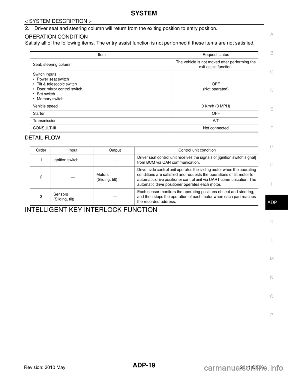
2. Driver seat and steering column will return from the exiting position to entry position.
OPERATION CONDITION
Satisfy all of the following items. The entry assist f unction is not performed if these items are not satisfied.
DETAIL FLOW
INTELLIGENT KEY INTERLOCK FUNCTION
Item Request status
Seat, steering column The vehicle is not moved after performing the
exit assist function.
Switch inputs
Power seat switch
Tilt & telescopic switch
Door mirror control switch
Set switch
Memory switch OFF
(Not operated)
Vehicle speed 0 Km/h (0 MPH)
Sta rte r OFF
Transmission A/T
CONSULT-III Not connected
Order Input Output Control unit condition
1 Ignition switch — Driver seat control unit receives the signals of [ignition switch signal]
from BCM via CAN communication.
2— Motors
(Sliding, tilt)Driver side control unit operates the sliding motor when the operating
conditions are satisfied and requests the operations of tilt motor to
automatic drive positioner control unit via UART communication. The
automatic drive positioner operates each motor.
3 Sensors
(Sliding, tilt) —Each sensor monitors the operating positions of seat and steering,
and then stops the operation of each motor when each part reaches
the recorded address.
Revision: 2010 May2011 QX56
Page 29 of 5598
ADP-20
< SYSTEM DESCRIPTION >
SYSTEM
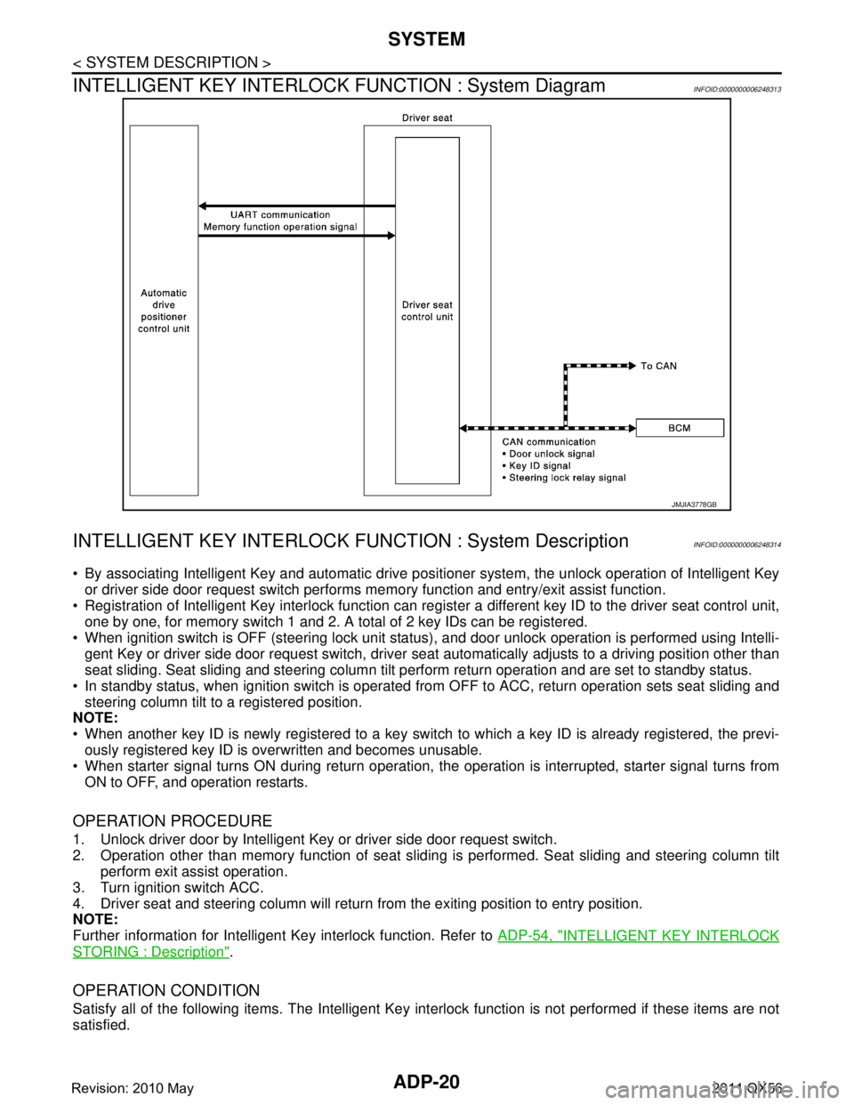
INTELLIGENT KEY INTERLOCK FUNCTION : System Diagram
INFOID:0000000006248313
INTELLIGENT KEY INTERLOCK F UNCTION : System DescriptionINFOID:0000000006248314
By associating Intelligent Key and automatic drive po sitioner system, the unlock operation of Intelligent Key
or driver side door request switch performs me mory function and entry/exit assist function.
Registration of Intelligent Key interlock function can regist er a different key ID to the driver seat control unit,
one by one, for memory switch 1 and 2. A total of 2 key IDs can be registered.
When ignition switch is OFF (steering lock unit status ), and door unlock operation is performed using Intelli-
gent Key or driver side door request swit ch, driver seat automatically adjusts to a driving position other than
seat sliding. Seat sliding and steering column tilt perform return operation and are set to standby status.
In standby status, when ignition switch is operated from OFF to ACC, return operation sets seat sliding and
steering column tilt to a registered position.
NOTE:
When another key ID is newly registered to a key switch to which a key ID is already registered, the previ-
ously registered key ID is overwritten and becomes unusable.
When starter signal turns ON during return operation, the operation is interrupted, starter signal turns from
ON to OFF, and operation restarts.
OPERATION PROCEDURE
1. Unlock driver door by Intelligent Key or driver side door request switch.
2. Operation other than memory functi on of seat sliding is performed. Seat sliding and steering column tilt
perform exit assist operation.
3. Turn ignition switch ACC.
4. Driver seat and steering column will return from the exiting position to entry position.
NOTE:
Further information for Intelligent Key interlock function. Refer to ADP-54, "
INTELLIGENT KEY INTERLOCK
STORING : Description".
OPERATION CONDITION
Satisfy all of the following items. The Intelligent Key interlock function is not performed if these items are not
satisfied.
JMJIA3778GB
Revision: 2010 May2011 QX56
Page 30 of 5598
SYSTEMADP-21
< SYSTEM DESCRIPTION >
C
DE
F
G H
I
K L
M A
B
ADP
N
O P
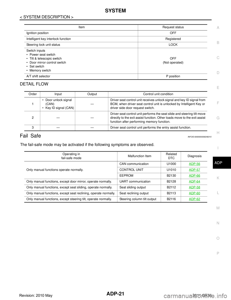
DETAIL FLOW
Fail SafeINFOID:0000000006248315
The fail-safe mode may be activated if the following symptoms are observed.
Item Request status
Ignition position OFF
Intelligent key interlock function Registered
Steering lock unit status LOCK
Switch inputs
Power seat switch
Tilt & telescopic switch
Door mirror control switch
Set switch
Memory switch OFF
(Not operated)
A/T shift selector P position
Order Input Output Control unit condition
1 Door unlock signal
(CAN)
Key ID signal (CAN) —Driver seat control unit receives unlock signal and key ID signal from
BCM, when driver seat control unit is unlocked by Intelligent Key or
driver side door request switch.
2— — Driver seat control unit performs the seat slide and steering tilt move
directly to the exit assist function. Other loads move to the exit assist
function after performing memory function.
3 — — Driver seat control unit performs the entry assist function.
Operating in
fail-safe mode Malfunction Item
Related
DTC Diagnosis
Only manual functions operate normally. CAN communication U1000
ADP-56
CONTROL UNIT U1010ADP-57
EEPROM B2130ADP-66
Only manual functions, except door mirror, operate normally. UART communication B2128 ADP-64
Only manual functions, except seat sliding, operate normally. Seat sliding output B2112ADP-58
Only manual functions, except seat reclining, operate normally. Seat reclining output B2113ADP-60
Only manual functions, except steering tilt, operate normally. Steering column tilt output B2116ADP-62
Revision: 2010 May2011 QX56
Page 31 of 5598

ADP-22
< SYSTEM DESCRIPTION >
DIAGNOSIS SYSTEM (DRIVER SEAT CONTROL UNIT)
DIAGNOSIS SYSTEM (DRIVER SEAT CONTROL UNIT)
CONSULT-III FunctionINFOID:0000000006248316
The automatic drive positioner system can be c hecked and diagnosed for component operation using CON-
SULT-III.
APPLICATION ITEMS
SELF-DIAGNOSIS RESULTS
Refer to ADP-31, "DTCIndex".
DATA MONITOR
Diagnostic mode Description
Ecu Identification Displays part numbers of driver seat control unit.
Self Diagnostic Result Performs self-diagnosis for the auto drive positioner system and displays the results.
Data Monitor Displays input signals transmitted from various switches and sensors to driver seat control unit
in real time.
Active Test Drives each output unit.
Work support Changes the setting for each system function.
Monitor Item Unit Main
Signals Selection
From
Menu Contents
STARTER SW “ON/OFF” ××Ignition key switch ON (START, ON) /OFF (ACC, OFF) sta-
tus judged from the ignition switch signal.
SET SW “ON/OFF” ××ON/OFF status judged from the setting switch signal.
MEMORY SW 1 “ON/OFF” ××ON/OFF status judged from the seat memory switch 1 sig-
nal.
MEMORY SW 2 “ON/OFF” ××ON/OFF status judged from the seat memory switch 2 sig-
nal.
DETENT SW “ON/OFF” ××The A/T shift selector position
“OFF (P position) / ON (other
than P position)” judged from the detention switch signal.
STEERING STATUS “LOCK/UN-
LOCK” ××
LOCK/UNLOCK status judged from steering lock unit.
SLIDE SW–FR “ON/OFF” ××ON/OFF status judged from the sliding switch (forward) sig-
nal.
SLIDE SW–RR “ON/OFF” ××ON/OFF status judged from the sliding switch (backward)
signal.
RECLN SW–FR “ON/OFF” ××ON/OFF status judged from the reclining switch (forward)
signal.
RECLN SW–RR “ON/OFF” ××ON/OFF status judged from the reclining switch (backward)
signal.
LIFT FR SW–UP “ON/OFF” ××ON/OFF status judged from the lifting switch front (up) sig-
nal.
LIFT FR SW–DN “ON/OFF” ××ON/OFF status judged from the lifting switch front (down)
signal.
LIFT RR SW–UP “ON/OFF” ××ON/OFF status judged from the lifting switch rear (up) sig-
nal.
LIFT RR SW–DN “ON/OFF” ××ON/OFF status judged from the lifting switch rear (down)
signal.
TILT SW-UP “ON/OFF” ××ON/OFF status judged from the tilt switch (up) signal.
TILT SW-DOWN “ON/OFF” ××ON/OFF status judged from the tilt switch (down) signal.
Revision: 2010 May2011 QX56