lock INFINITI QX56 2011 Factory Service Manual
[x] Cancel search | Manufacturer: INFINITI, Model Year: 2011, Model line: QX56, Model: INFINITI QX56 2011Pages: 5598, PDF Size: 94.53 MB
Page 3400 of 5598

IP-10
< SYMPTOM DIAGNOSIS >
SQUEAK AND RATTLE TROUBLE DIAGNOSES
1. Trunk lid dumpers out of adjustment
2. Trunk lid striker out of adjustment
3. Trunk lid torsion bars knocking together
4. A loose license plate or bracket
Most of these incidents can be repaired by adjusting, securing, or insulating the item(s) or component(s) caus-
ing the noise.
SUNROOF/HEADLINING
Noises in the sunroof / headlining area can often be traced to one of the following items:
1. Sunroof lid, rail, linkage, or seals making a rattle or light knocking noise
2. Sunvisor shaft shaking in the holder
3. Front or rear windshield touching headlining and squeaking
Again, pressing on the components to stop the noise while duplicating the conditions can isolate most of these
incidents. Repairs usually consist of insulating with felt cloth tape.
SEATS
When isolating seat noise it is important to note t he position the seat is in and the load placed on the seat
when the noise occurs. These conditions should be duplic ated when verifying and isolating the cause of the
noise.
Causes of seat noise include:
1. Headrest rods and holder
2. A squeak between the seat pad cushion and frame
3. The rear seatback lock and bracket
These noises can be isolated by moving or pressing on the suspected components while duplicating the con-
ditions under which the noise occurs. Most of thes e incidents can be repaired by repositioning the component
or applying urethane tape to the contact area.
UNDERHOOD
Some interior noise may be caused by components under the hood or on the engine wall. The noise is then
transmitted into the passenger compartment.
Causes of transmitted underhood noise include:
1. Any component mounted to the engine wall
2. Components that pass through the engine wall
3. Engine wall mounts and connectors
4. Loose radiator mounting pins
5. Hood bumpers out of adjustment
6. Hood striker out of adjustment
These noises can be difficult to isolate since they cannot be reached from the interior of the vehicle. The best
method is to secure, move, or insulate one component at a time and test drive the vehicle. Also, engine RPM
or load can be changed to isolate the noise. Repairs can usually be made by moving, adjusting, securing, or
insulating the component causing the noise.
Revision: 2010 May2011 QX56
Page 3404 of 5598

IP-14
< REMOVAL AND INSTALLATION >
INSTRUMENT PANEL ASSEMBLY
Removal and Installation
INFOID:0000000006113098
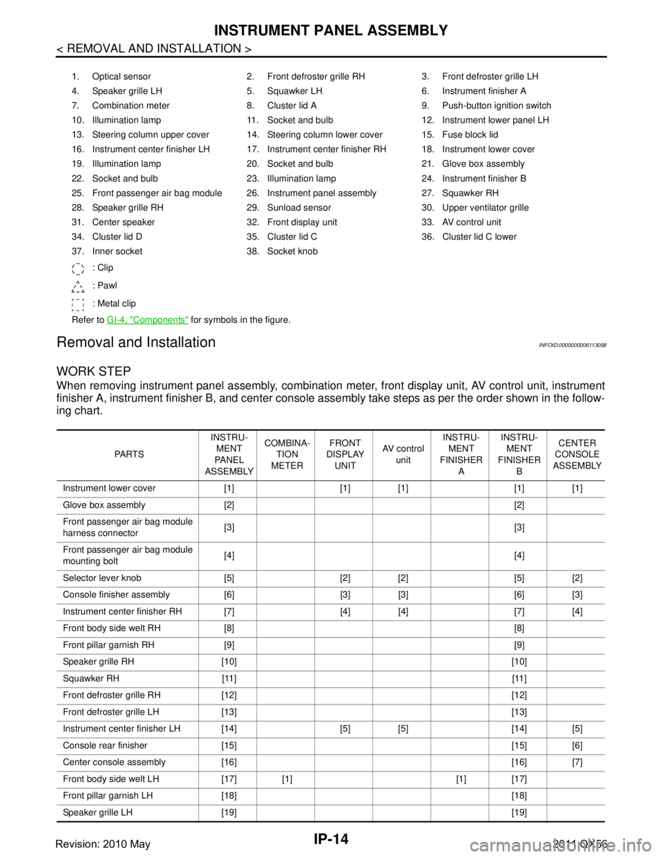
WORK STEP
When removing instrument panel assembly, combination meter, front display unit, AV control unit, instrument
finisher A, instrument fini sher B, and center console assembly take st eps as per the order shown in the follow-
ing chart.
1. Optical sensor 2. Front defroster grille RH 3. Front defroster grille LH
4. Speaker grille LH 5. Squawker LH 6. Instrument finisher A
7. Combination meter 8. Cluster lid A 9. Push-button ignition switch
10. Illumination lamp 11. Socket and bulb 12. Instrument lower panel LH
13. Steering column upper cover 14. Steering column lower cover 15. Fuse block lid
16. Instrument center finisher LH 17. Instrument center finisher RH 18. Instrument lower cover
19. Illumination lamp 20. Socket and bulb 21. Glove box assembly
22. Socket and bulb 23. Illumination lamp 24. Instrument finisher B
25. Front passenger air bag module 26. Instrument panel assembly 27. Squawker RH
28. Speaker grille RH 29. Sunload sensor 30. Upper ventilator grille
31. Center speaker 32. Front display unit 33. AV control unit
34. Cluster lid D 35. Cluster lid C 36. Cluster lid C lower
37. Inner socket 38. Socket knob
: Clip
: Pawl
: Metal clip
Refer to GI-4, "
Components" for symbols in the figure.
PA R T S INSTRU-
MENT
PA N E L
ASSEMBLY COMBINA-
TION
METER FRONT
DISPLAY
UNIT AV c o n t r o l
unit INSTRU-
MENT
FINISHER A INSTRU-
MENT
FINISHER B CENTER
CONSOLE
ASSEMBLY
Instrument lower cover [1] [1] [1] [1] [1]
Glove box assembly [2] [2]
Front passenger air bag module
harness connector [3] [3]
Front passenger air bag module
mounting bolt [4] [4]
Selector lever knob [5] [2] [2] [5] [2]
Console finisher assembly [6] [3] [3] [6] [3]
Instrument center finisher RH [7] [4] [4] [7] [4]
Front body side welt RH [8] [8]
Front pillar garnish RH [9] [9]
Speaker grille RH [10] [10]
Squawker RH [11] [11]
Front defroster grille RH [12] [12]
Front defroster grille LH [13] [13]
Instrument center finisher LH [14] [5] [5] [14] [5]
Console rear finisher [15] [15] [6]
Center console assembly [16] [16] [7]
Front body side welt LH [17] [1] [1] [17]
Front pillar garnish LH [18] [18]
Speaker grille LH [19] [19]
Revision: 2010 May2011 QX56
Page 3419 of 5598

REAR CONSOLE ASSEMBLYIP-29
< REMOVAL AND INSTALLATION >
C
DE
F
G H
I
K L
M A
B
IP
N
O P
REAR CONSOLE ASSEMBLY
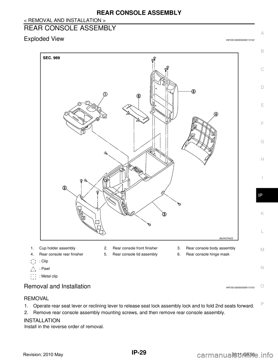
Exploded ViewINFOID:0000000006113102
Removal and InstallationINFOID:0000000006113103
REMOVAL
1. Operate rear seat lever or reclining lever to release seat lock assembly lock and to fold 2nd seats forward.
2. Remove rear console assembly mounting screws, and then remove rear console assembly.
INSTALLATION
Install in the reverse order of removal.
1. Cup holder assembly 2. Rear console front finisher 3. Rear console body assembly
4. Rear console rear finisher 5. Rear console lid assembly 6. Rear console hinge mask : Clip
: Pawl
: Metal clip
JMJIA3764ZZ
Revision: 2010 May2011 QX56
Page 3434 of 5598
![INFINITI QX56 2011 Factory Service Manual
LAN-14
< SYSTEM DESCRIPTION >[CAN FUNDAMENTAL]
TROUBLE DIAGNOSIS
Example: CAN-H, CAN-L Harness Short Circuit
CAN Diagnosis with CONSULT-IIIINFOID:0000000006220519
CAN diagnosis on CONSULT-III extract INFINITI QX56 2011 Factory Service Manual
LAN-14
< SYSTEM DESCRIPTION >[CAN FUNDAMENTAL]
TROUBLE DIAGNOSIS
Example: CAN-H, CAN-L Harness Short Circuit
CAN Diagnosis with CONSULT-IIIINFOID:0000000006220519
CAN diagnosis on CONSULT-III extract](/img/42/57033/w960_57033-3433.png)
LAN-14
< SYSTEM DESCRIPTION >[CAN FUNDAMENTAL]
TROUBLE DIAGNOSIS
Example: CAN-H, CAN-L Harness Short Circuit
CAN Diagnosis with CONSULT-IIIINFOID:0000000006220519
CAN diagnosis on CONSULT-III extracts the root
cause by receiving the following information.
Response to the system call
Control unit diagnosis information
Self-diagnosis
CAN diagnostic support monitor
SKIB8741E
Unit name Major symptom
ECM Engine torque limiting is affected, and shift harshness increases.
Engine speed drops.
BCM Reverse warning chime does not sound.
The front wiper moves under continuous operation mode even though the front
wiper switch being in the intermittent position.
The room lamp does not turn ON.
The engine does not start (if an error or malfunction occurs while turning the igni- tion switch OFF.)
The steering lock does not release (if an error or malfunction occurs while turning the ignition switch OFF.)
EPS control unit The steeri ng effort increases.
Combination meter The tachometer and the speedometer do not move.
Warning lamps turn ON.
Indicator lamps do not turn ON.
ABS actuator and electric unit (control unit) Normal operation.
TCM No impact on operation.
IPDM E/R When the ignition switch is ON,
The headlamps (Lo) turn ON.
The cooling fan continues to rotate.
Revision: 2010 May2011 QX56
Page 3450 of 5598
![INFINITI QX56 2011 Factory Service Manual
LAN-30
< SYSTEM DESCRIPTION >[CAN]
SYSTEM
P range signal T R R
R range signal T R R
Shift position signal R R T R R R R R
Tow mode indicator lamp
signalTR
Pre-roll over signal T R
Pre-tensioner oper INFINITI QX56 2011 Factory Service Manual
LAN-30
< SYSTEM DESCRIPTION >[CAN]
SYSTEM
P range signal T R R
R range signal T R R
Shift position signal R R T R R R R R
Tow mode indicator lamp
signalTR
Pre-roll over signal T R
Pre-tensioner oper](/img/42/57033/w960_57033-3449.png)
LAN-30
< SYSTEM DESCRIPTION >[CAN]
SYSTEM
P range signal T R R
R range signal T R R
Shift position signal R R T R R R R R
Tow mode indicator lamp
signalTR
Pre-roll over signal T R
Pre-tensioner operation
signal TR
AFS OFF indicator lamp
signal TR
A/C switch operation signal T R
Rear window defogger
switch signal TR
System selection signal T R
System setting signal TR R
RT
RT
Automatic back door re-
quest signal TR
Back door lock status signal T R
Buzzer output signal TR
RT
Buzzer request signal TR
RT
Dimmer signal T R R
Door switch signal T R R R R
Door unlock signal T R
Front fog light request sig-
nal TR
Front wiper request signal T R R
Handle position signal T R
Headlamp washer request
signal TR
High beam request signal T R R
Horn reminder signal T R
Ignition switch ON signal TRRR
RT
Ignition switch signal T R
Interlock/PNP switch signal TR
RT
Key ID signal T R
Key switch signal T R
Key warning lamp signal T R
Low beam request signal T R Signal name
ECM
4WD
ABS
TCM
A-BAG
AFSAV
BCM
CGW
HVAC
M&A
STRG
TPMS
IPDM-E ADP
PSB
E-SUS ICC
PWBD
Revision: 2010 May2011 QX56
Page 3451 of 5598
![INFINITI QX56 2011 Factory Service Manual
LAN
SYSTEMLAN-31
< SYSTEM DESCRIPTION > [CAN]
C
D
E
F
G H
I
J
K L
B A
O P
N
Meter display signal
TR
RT
Oil pressure switch signal TR
RT
Position light request signal T R R
Rear fog light status signa INFINITI QX56 2011 Factory Service Manual
LAN
SYSTEMLAN-31
< SYSTEM DESCRIPTION > [CAN]
C
D
E
F
G H
I
J
K L
B A
O P
N
Meter display signal
TR
RT
Oil pressure switch signal TR
RT
Position light request signal T R R
Rear fog light status signa](/img/42/57033/w960_57033-3450.png)
LAN
SYSTEMLAN-31
< SYSTEM DESCRIPTION > [CAN]
C
D
E
F
G H
I
J
K L
B A
O P
N
Meter display signal
TR
RT
Oil pressure switch signal TR
RT
Position light request signal T R R
Rear fog light status signal T R
Rear window defogger con-
trol signal TR
RT
Sleep wake up signal T R R R R R R
Starter control relay signal T R
Starter relay status signal TRR
RT
Starting mode signal T R
Steering lock relay signal TRR
RT
Theft warning horn request
signal TR
Turn indicator signal R T R R
A/C display signal R T
A/C ON signal R T
Ambient temperature signal T R
Blower fan ON signal R T
Distance to empty signal R T
Fuel level low warning sig-
nal RT
Fuel level sensor signal R T
Manual mode shift down
signal RT
Manual mode shift up sig-
nal RT
Manual mode signal R T
Non-manual mode signal R T
Odometer signal R T
Parking brake switch signal R R T R R
Sleep-ready signal RT
RT
RT
Tow mode switch signal R T
Wake up signal RT
RT
Steering angle sensor mal-
function signal RR T R R
Steering angle sensor sig-
nal RR RR T R R
Steering angle speed signal R T R R Signal name
ECM
4WD
ABS
TCM
A-BAG AFS
AV
BCM
CGW
HVAC M&A
STRG
TPMS
IPDM-E
ADPPSB
E-SUS ICC
PWBD
Revision: 2010 May2011 QX56
Page 3452 of 5598
![INFINITI QX56 2011 Factory Service Manual
LAN-32
< SYSTEM DESCRIPTION >[CAN]
SYSTEM
Steering calibration signal R T R
Hazard request signalRT
RT
Horn request signal R T
Low tire pressure warning
lamp signal RT
Tire pressure data signal R T
INFINITI QX56 2011 Factory Service Manual
LAN-32
< SYSTEM DESCRIPTION >[CAN]
SYSTEM
Steering calibration signal R T R
Hazard request signalRT
RT
Horn request signal R T
Low tire pressure warning
lamp signal RT
Tire pressure data signal R T](/img/42/57033/w960_57033-3451.png)
LAN-32
< SYSTEM DESCRIPTION >[CAN]
SYSTEM
Steering calibration signal R T R
Hazard request signalRT
RT
Horn request signal R T
Low tire pressure warning
lamp signal RT
Tire pressure data signal R T
A/C compresso r feedback
signal RRT
Detention switch signal R T R
Engine restart control sig-
nal RT
Front wiper stop position
signal RT
High beam status signal R T
Hood switch signal R T
Low beam status signal R R T
Push-button ignition switch
status signal RT
Starter control relay signal R T
Steering lock unit status
signal RT
CK SUSP indi cator lamp
signal RT
Brake fluid pressure control
signal R
T
BSW warning lamp signal R T
IBA OFF indicator lamp sig-
nal RT
IBA operation signal RT
ICC operation signal R T
ICC warning lamp signal R T
Lane departure warning
lamp signal RT
LDP ON indicator lamp sig-
nal RT
Target yaw moment signal R T
Signal name
ECM
4WD
ABS
TCM
A-BAG
AFSAV
BCM
CGW
HVAC
M&A
STRG
TPMS
IPDM-E ADP
PSB
E-SUS ICC
PWBD
Revision: 2010 May2011 QX56
Page 3656 of 5598

PREPARATIONLU-3
< PREPARATION >
C
DE
F
G H
I
J
K L
M A
LU
NP
O
PREPARATION
PREPARATION
Special Service ToolINFOID:0000000006289612
Commercial Service ToolINFOID:0000000006289613
Tool number
(Kent-Moore No.)
Tool name
Description
ST25051001
(J-25695-1)
Oil pressure gauge Measuring oil pressure
Maximum measuring range:
2,452 kPa (25 kg/cm
2, 356 psi)
ST25052000
(J-25695-2)
Hose Adapting oil pressure gauge to cylinder block
K V 1 0 1111 0 0
(J-37228)
Seal cutter Removing steel oil pan and rear timing chain
case
KV10115801
(J-38956)
Oil filter wrench Removing and installing oil filter
a: 64.3 mm (2.531 in)
S-NT050
S-NT559
NT046
S-NT375
Revision: 2010 May2011 QX56
Page 3660 of 5598

ENGINE OILLU-7
< PERIODIC MAINTENANCE >
C
DE
F
G H
I
J
K L
M A
LU
NP
O
PERIODIC MAINTENANCE
ENGINE OIL
InspectionINFOID:0000000006289616
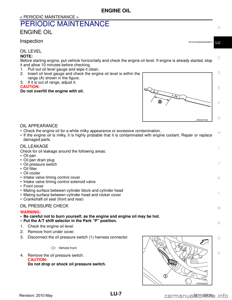
OIL LEVEL
NOTE:
Before starting engine, put vehicle horizontally and check
the engine oil level. If engine is already started, stop
it and allow 10 minutes before checking.
1. Pull out oil level gauge and wipe it clean.
2. Insert oil level gauge and check the engine oil level is within the range (A) shown in the figure.
3. If it is out of range, adjust it.
CAUTION:
Do not overfill the engine with oil.
OIL APPEARANCE
Check the engine oil for a white milky appearance or excessive contamination.
If the engine oil is milky, it is highly probable that it is contaminated with engine coolant. Repair or replace
damaged parts.
OIL LEAKAGE
Check for oil leakage around the following areas:
Oil pan
Oil pan drain plug
Oil pressure switch
Oil filter
Oil cooler
Intake valve timing control cover
Intake valve timing control solenoid valve
Front cover
Mating surface between cylinder block and cylinder head
Mating surface between cylinder head and rocker cover
Crankshaft oil seal (front and rear)
OIL PRESSURE CHECK
WARNING:
• Be careful not to burn yourself, as th e engine and engine oil may be hot.
Put the A/T shift selector in the Park “P” position.
1. Check the engine oil level.
2. Remove front under cover.
3. Disconnect the oil pressure switch (1) harness connector.
4. Remove the oil pressure switch. CAUTION:
Do not drop or shock oil pressure switch.
JPBIA0070ZZ
:Vehicle front
JPBIA3526ZZ
Revision: 2010 May2011 QX56
Page 3661 of 5598
![INFINITI QX56 2011 Factory Service Manual
LU-8
< PERIODIC MAINTENANCE >
ENGINE OIL
5. Install the oil pressure gauge [SST: ST25051001 (J25695-1)] (A)and hose [SST: ST25052000 (J25695-2)] (B).
6. Start the engine and warm it up to normal oper INFINITI QX56 2011 Factory Service Manual
LU-8
< PERIODIC MAINTENANCE >
ENGINE OIL
5. Install the oil pressure gauge [SST: ST25051001 (J25695-1)] (A)and hose [SST: ST25052000 (J25695-2)] (B).
6. Start the engine and warm it up to normal oper](/img/42/57033/w960_57033-3660.png)
LU-8
< PERIODIC MAINTENANCE >
ENGINE OIL
5. Install the oil pressure gauge [SST: ST25051001 (J25695-1)] (A)and hose [SST: ST25052000 (J25695-2)] (B).
6. Start the engine and warm it up to normal operating temperature.
7. Check the engine oil pressure with engine running under no-load. Refer to LU-17, "
EngineOilPressure".
CAUTION:
If the difference is extreme, check the oil passages and oil pump for leaks and blockages.
8. After the inspections, install oil pressure switch as follows:
a. Remove old liquid gasket adhering to oil pressure switch and engine.
b. Apply liquid gasket and tighten oil pressure switch to the specification. Use Genuine RTV Silicone Seal ant or equivalent. Refer to GI-22, "
Recommended Chemical Prod-
ucts and Sealants".
c. After warming up engine, make sure there is no leakage of engine oil with engine running.
DrainingINFOID:0000000006289617
WARNING:
Be careful not to burn yourself, as th e engine and engine oil may be hot.
Prolonged and repeated contact with used engine oil may cause skin cancer; try to avoid direct skin
contact with used oil. If skin contact is made, wash thoroughly with soap or hand cleaner as soon as
possible.
1. Warm up the engine, and check for any oil leaks.
2. Stop the engine and wait for at least 10 minutes.
3. Remove drain plug and oil filler cap to drain the old oil.
RefillingINFOID:0000000006289618
1. Install drain plug with new washer. CAUTION:
Be sure to clean drain plug and install with new washer.
2. Refill with new engine oil. Engine oil specification and viscosity:
Refer to MA-10, "
Fluids and Lubricants".
CAUTION:
The refill capacity depends on the engine oi l temperature and drain time. Use these specifica-
tions for reference only.
Always use oil level gauge to determine the proper amount of engine oil in engine.
3. Warm up the engine and check area around drain plug and oil filter for engine oil leakage.
4. Stop the engine and wait for 10 minutes.
5. Check the engine oil level. Refer to LU-7, "
Inspection".
JPBIA0074ZZ
Oil pressure switch torque : Refer to EM-57, "Exploded View".
Tightening torque : Refer to EM-54, "
Exploded View".
Engine oil capacity : Refer to LU-17, "
Periodical Maintenance Specification".
Revision: 2010 May2011 QX56