trunk release INFINITI QX56 2011 Factory Service Manual
[x] Cancel search | Manufacturer: INFINITI, Model Year: 2011, Model line: QX56, Model: INFINITI QX56 2011Pages: 5598, PDF Size: 94.53 MB
Page 1677 of 5598

BACK DOOR OPENER SWITCHDLK-141
< DTC/CIRCUIT DIAGNOSIS >
C
DE
F
G H
I
J
L
M A
B
DLK
N
O P
BACK DOOR OPENER SWITCH
Component Function CheckINFOID:0000000006225955
1.CHECK FUNCTION
1. Select “TRUNK” of “BCM” using CONSULT-III.
2. Select “TR/BD OPEN SW” in “DATA MONITOR” mode.
3. Check that the function operates normall y according to the following conditions.
Is the inspection result normal?
YES >> Back door opener switch is OK.
NO >> Refer to DLK-141, "
Diagnosis Procedure".
Diagnosis ProcedureINFOID:0000000006225956
1.CHECK BACK DOOR OPEN INPUT SIGNAL
1. Turn ignition switch OFF.
2. Disconnect back door opener switch assembly connector.
3. Check signal between back door opener switch assembly harness connector and ground.
Is the inspection result normal?
YES >> GO TO 3.
NO >> GO TO 2.
2.CHECK BACK DOOR OPENER SWITCH CIRCUIT
1. Disconnect BCM connector.
2. Check continuity between BCM harness connector and back door opener switch assembly harness con-
nector.
3. Check continuity between BCM harness connector and ground.
Is the inspection result normal?
YES >> Replace BCM. Refer to BCS-81, "Removal and Installation".
NO >> Repair or replace harness.
Monitor item Condition Status
TR/BD OPEN SW Back door opener switch Pressed ON
Released OFF
(+)
(–)Signal
(Reference value)
Back door opener switch assembly
Connector Terminal
D154 1 Ground
JPMIA0012GB
BCM Back door opener switch assembly Continuity
Connector Terminal Connector Terminal
M68 30 D154 1 Existed
BCM GroundContinuity
Connector Terminal
M68 30 Not existed
Revision: 2010 May2011 QX56
Page 2975 of 5598

HOW TO READ WIRING DIAGRAMSGI-11
< HOW TO USE THIS MANUAL >
C
DE
F
G H
I
J
K L
M B
GI
N
O P
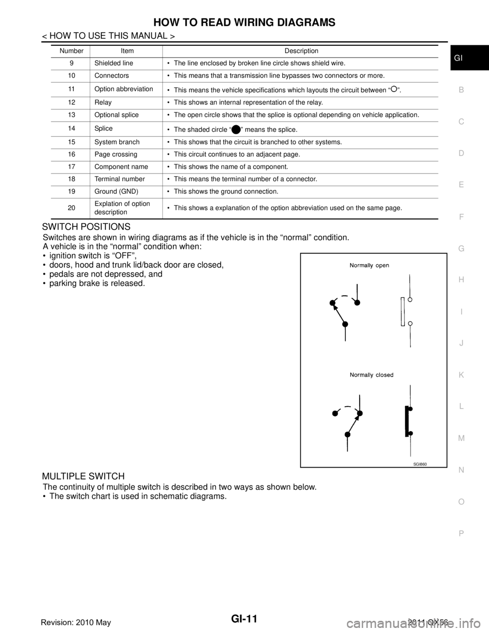
SWITCH POSITIONS
Switches are shown in wiring diagrams as if the vehicle is in the “normal” condition.
A vehicle is in the “normal” condition when:
ignition switch is “OFF”,
doors, hood and trunk lid/back door are closed,
pedals are not depressed, and
parking brake is released.
MULTIPLE SWITCH
The continuity of multiple switch is described in two ways as shown below.
The switch chart is used in schematic diagrams.
9 Shielded line The line enclosed by broken line circle shows shield wire.
10 Connectors This means that a transmission line bypasses two connectors or more.
11 Option abbreviation This means the vehicle specifications which layouts the circuit between “ ”.
12 Relay This shows an internal representation of the relay.
13 Optional splice The open circle shows that the splice is optional depending on vehicle application.
14 Splice The shaded circle “ ” means the splice.
15 System branch This shows that the circuit is branched to other systems.
16 Page crossing This circuit continues to an adjacent page.
17 Component name This shows the name of a component.
18 Terminal number This means the terminal number of a connector.
19 Ground (GND) This shows the ground connection.
20 Explation of option
description This shows a explanation of the option abbreviation used on the same page.
Number Item Description
SGI860
Revision: 2010 May2011 QX56