door INFINITI QX56 2011 Factory Workshop Manual
[x] Cancel search | Manufacturer: INFINITI, Model Year: 2011, Model line: QX56, Model: INFINITI QX56 2011Pages: 5598, PDF Size: 94.53 MB
Page 193 of 5598

AV
DIAGNOSIS SYSTEM (AROUND VIEW MONITOR CONTROL UNIT)
AV-45
< SYSTEM DESCRIPTION >
C
D E
F
G H
I
J
K L
M B A
O P
Calibrating Camera Image
Perform the calibration of camera image caused by the incorrect mounting position of each camera, etc. Always perform calibration
after performing the following work.
- When each camera or each camera mount (door mirror, front grille,
etc.) is removed
- When replacing around view monitor control unit
When performing the calibration initialization, it can be set to the
NISSAN factory shipment condition.
Refer to AV-112, "
Work Procedure" for the calibration procedure.
Calibrating Camera Image item
CAUTION:
Type of Steer. Angle Sensor Abslt. The input type of steering angle sensor is displayed. (“Abslt.” is displayed on this
model.)
Type of Steer. Gear ratio 1 The type of steering gear ratio is displayed. (“1” is displayed on this model.)
Left or Right Steer. Right/Left The steering position is displayed.
Rear Camera Image Output signal OK/NG The input status of rear camera image signal is displayed by OK/NG in real time.
Rear Camera COMM Status OK/NG The communication status with rear camera is displayed by OK/NG in real time.
Rear Camera COMM Line OK/NG The status of communication line with rear camera is displayed by OK/NG in real
time.
Front Camera Image Output signal OK/NG The input status of front camera image signal is displayed by OK/NG in real time.
Front Camera COMM Status OK/NG The communication status with front camera is displayed by OK/NG in real time.
Front Camera COMM Line OK/NG The status of communication line with front camera is displayed by OK/NG in real
time.
Pass-Side Camera Image Output sig-
nal OK/NGThe input status of side camera RH image signal is displayed by OK/NG in real
time.
Pass-Side Camera COMM Status OK/NG The communication status with side camera RH is displayed by OK/NG in real
time.
Pass-Side Camera COMM Line OK/NG The status of communication line with side camera RH is displayed by OK/NG in
real time.
Dr-Side Camera Image Output signal OK/NG The input status of side camera LH image signal is displayed by OK/NG in real
time.
Dr-Side Camera COMM Status OK/NG The communication status with side camera LH is displayed by OK/NG in real
time.
Dr-Side Camera COMM Line OK/NG The status of communication line with side camera LH is displayed by OK/NG in
real time.
Diagnosis item Display Description
JSNIA2379ZZ
Adjustment range
Rotating direction : 31 patterns (16 on the center)
Upper/lower direction : (
−99) – (+99)
Left/right direction : ( −99) – (+99)
Items Description
Rear Camera Performs the ca libration of rear camera.
Pass-Side Camera Performs the ca libration of side camera RH.
Front Camera Performs the ca libration of front camera.
Dr-Side Camera Performs the calib ration of side camera LH.
Initialize Camera Image Calibration
*The calibration can be initialized to the factory shipment setting.
Revision: 2010 May2011 QX56
Page 217 of 5598

AV
BOSE AMP.AV-69
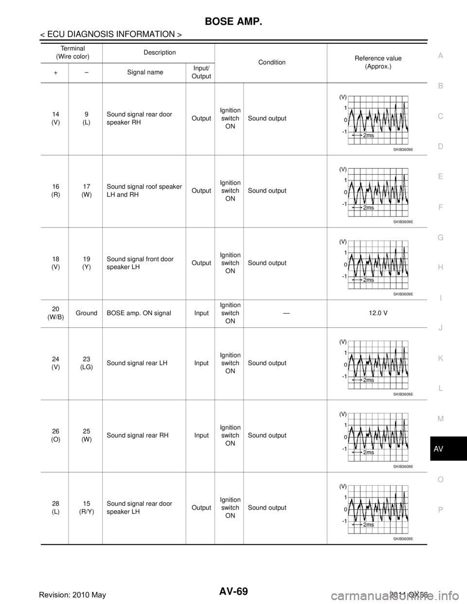
< ECU DIAGNOSIS INFORMATION >
C
DE
F
G H
I
J
K L
M B A
O P14
(V) 9
(L) Sound signal rear door
speaker RH
OutputIgnition
switch ON Sound output
16
(R) 17
(W) Sound signal roof speaker
LH and RH
OutputIgnition
switch ON Sound output
18
(V) 19
(Y) Sound signal front door
speaker LH
OutputIgnition
switch ON Sound output
20
(W/B) Ground BOSE amp. ON signal Input Ignition
switch ON — 12.0 V
24
(V) 23
(LG) Sound signal rear LH Input Ignition
switch ON Sound output
26
(O) 25
(W) Sound signal rear RH Input Ignition
switch
ON Sound output
28
(L) 15
(R/Y) Sound signal rear door
speaker LH
OutputIgnition
switch ON Sound output
Te r m i n a l
(Wire color) Description
ConditionReference value
(Approx.)
+ – Signal name Input/
Output
SKIB3609E
SKIB3609E
SKIB3609E
SKIB3609E
SKIB3609E
SKIB3609E
Revision: 2010 May2011 QX56
Page 218 of 5598

AV-70
< ECU DIAGNOSIS INFORMATION >
BOSE AMP.
29
(GR/R) 30
(G/R) Sound signal center speak-
er
OutputIgnition
switch ON Sound output
31
(L/W) 32
(L) Sound signal front door
speaker RH
OutputIgnition
switch ON Sound output
33
(Y/L) 34
(Y/G) Sound signal front RH Input Ignition
switch ON Sound output
35
(L) 36
(P) Sound signal front LH Input Ignition
switch
ON Sound output
37
(R/W) Ground Mode change signal Input Ignition
switch
ON Driver's Audio Stage ON 0 V
Driver's Audio Stage OFF 8.5 V
Te r m i n a l
(Wire color) Description
ConditionReference value
(Approx.)
+ – Signal name Input/
Output
SKIB3609E
SKIB3609E
SKIB3609E
SKIB3609E
Revision: 2010 May2011 QX56
Page 260 of 5598

AV-112
< BASIC INSPECTION >
CALIBRATING CAMERA IMAGE (AROUND VIEW MONITOR)
CALIBRATING CAMERA IMAGE (AROUND VIEW MONITOR)
DescriptionINFOID:0000000006216246
Perform the calibration and perform the writing to the around view monitor control unit when removing and
replacing each camera, removing the camera mounting part s (front grille, door mirror, etc.) and replacing the
around view monitor control unit.
Align the white lines on the road near the vehicle at the boundary of each camera image by this camera cal-
ibration. The white lines far from the vehicle may not be aligned at the boundary of each camera image. The
farther the line, the greater the difference is.
Work ProcedureINFOID:0000000006216915
Calibration flowchart
Following the flowchart shown in the figure, perform the calibration.
NOTE:
In the un-match display, the un-match camera position is indicated
as “ ” on the birds-eye view.
Calibration procedure
1.AROUND VIEW MONITOR SCREEN CONFIRMATION
JPNIA1341GB
JSNIA2378ZZ
Revision: 2010 May2011 QX56
Page 335 of 5598

AV
SIDE CAMERA LH COMMUNICATION SIGNAL CIRCUIT
AV-187
< DTC/CIRCUIT DIAGNOSIS >
C
D E
F
G H
I
J
K L
M B A
O P
SIDE CAMERA LH COMMUNI CATION SIGNAL CIRCUIT
DescriptionINFOID:0000000006216358
Around view monitor control unit supplies to the front camera, rear camera and side camera. And then it
superimpose the images from each camera and outputs then to the front display unit.
Superimpose the guiding lines, predictive course line and sonar indicator to the camera image that outputs
to the front display unit.
Around view monitor control unit performs the rec eption/transmission of communication signal with each
camera.
Diagnosis ProcedureINFOID:0000000006216359
1.CHECK CONTINUITY COMMUNI CATION SIGNAL CIRCUIT
1. Turn ignition switch OFF.
2. Disconnect around view monitor control unit connector and door mirror (driver side) connector.
3. Check continuity between around view monitor control unit harness connector and door mirror (driver side) harness connector.
4. Check continuity between around view monitor control unit harness connector and ground.
Is inspection result normal?
YES >> GO TO 2.
NO >> Repair harness or connector.
2.CHECK COMMUNICATION SIGNAL
1. Connect around view monitor control unit c onnector and door mirror (driver side) connector.
2. Turn ignition switch ON.
3. Check signal between around view monitor control unit harness connector and ground.
Is inspection result normal?
YES >> Replace around view monitor control unit. Refer to AV-233, "Removal and Installation".
NO >> Replace side camera LH. Refer to AV-236, "
Removal and Installation".
Around view monitor control
unit Door mirror
(driver side) Continuity
Connector Terminal Connector Terminal
M49 47 D3 3 Existed
Around view monitor control unit GroundContinuity
Connector Terminal
M49 47 Not existed
(+)
(− ) Condition Reference value
Around view monitor control
unit
Connector Terminal
M49 47 Ground “CAMERA” switch is ON or shift
position is “R”.
JSNIA0836GB
Revision: 2010 May2011 QX56
Page 336 of 5598

AV-188
< DTC/CIRCUIT DIAGNOSIS >
SIDE CAMERA LH IMAGE SIGNAL CIRCUIT
SIDE CAMERA LH IMAGE SIGNAL CIRCUIT
DescriptionINFOID:0000000006216360
Around view monitor control unit supplies to the front camera, rear camera and side came\
ra. And then itsuperimpose the images from each camera and outputs then to the front display unit.
Superimpose the guiding lines, predictive course line and sonar indicator to the camera image that outputs
to the front display unit.
Around view monitor control unit performs the rec eption/transmission of communication signal with each
camera.
Diagnosis ProcedureINFOID:0000000006216361
1.CHECK CONTINUITY SIDE CAMERA LH POWER SUPPLY AND GROUND CIRCUIT
1. Turn ignition switch OFF.
2. Disconnect around view monitor control unit connector and door mirror (driver side) connector.
3. Check continuity between around view monitor c ontrol unit harness connector and door mirror (driver
side) harness connector.
4. Check continuity between around view m onitor control unit harness connector and ground.
Is inspection result normal?
YES >> GO TO 2.
NO >> Repair harness or connector.
2.CHECK VOLTAGE SIDE CA MERA LH POWER SUPPLY
1. Connect around view monitor control unit connector and door mirror (driver side) connector.
2. Turn ignition switch ON.
3. Check voltage between around view monito r control unit harness connector and ground.
Is inspection result normal?
YES >> GO TO 3.
NO >> Replace around view monitor control unit. Refer to AV-233, "
Removal and Installation".
3.CHECK CONTINUITY SIDE CAMERA LH IMAGE SIGNAL CIRCUIT
1. Turn ignition switch OFF.
2. Disconnect around view monitor control unit connector and door mirror (driver side) connector.
3. Check continuity between around view monitor c ontrol unit harness connector and door mirror (driver
side) harness connector.
Around view monitor control
unit Door mirror (driver side)
Continuity
Connector Terminals Connector Terminals
M49 48
D3 6
Existed
50 18
Around view monitor control unit GroundContinuity
Connector Terminal
M49 48 Not existed
(+)
(− ) Condition Vo l ta g e
(Approx.)
Around view monitor control
unit
Connector Terminal
M49 48 Ground “CAMERA” switch is ON or
shift position is “R”.
6.0 V
Revision: 2010 May2011 QX56
Page 337 of 5598

AV
SIDE CAMERA LH IMAGE SIGNAL CIRCUITAV-189
< DTC/CIRCUIT DIAGNOSIS >
C
DE
F
G H
I
J
K L
M B A
O P4. Check continuity between around view monitor control unit harness connector and ground.
Is inspection result normal?
YES >> GO TO 4.
NO >> Repair harness or connector.
4.CHECK SIDE CAMERA LH IMAGE SIGNAL
1. Connect around view monitor control unit c onnector and door mirror (driver side) connector.
2. Turn ignition switch ON.
3. Check signal between around view monitor control unit harness connector.
Is inspection result normal?
YES >> Replace around view monitor control unit. Refer to AV-233, "Removal and Installation".
NO >> Replace side camera LH. Refer to AV-236, "
Removal and Installation".
Around view monitor control
unit Door mirror (driver side)
Continuity
Connector Terminals Connector Terminals
M49 51
D3 5
Existed
52 17
Around view monitor control unit GroundContinuity
Connector Terminals
M49 51, 52 Not existed
(+) ( −)
Condition Reference value
Around view monitor control unit
Connector Terminal Connector Terminal
M4951M4952 “CAMERA” switch is ON or
shift position is “R”.
JSNIA0834GB
Revision: 2010 May2011 QX56
Page 338 of 5598

AV-190
< DTC/CIRCUIT DIAGNOSIS >
SIDE CAMERA RH COMMUNICATION SIGNAL CIRCUIT
SIDE CAMERA RH COMMUNICATION SIGNAL CIRCUIT
DescriptionINFOID:0000000006216362
Around view monitor control unit supplies to the front camera, rear camera and side came\
ra. And then it
superimpose the images from each camera and outputs then to the front display unit.
Superimpose the guiding lines, predictive course line and sonar indicator to the camera image that outputs
to the front display unit.
Around view monitor control unit performs the rec eption/transmission of communication signal with each
camera.
Diagnosis ProcedureINFOID:0000000006216363
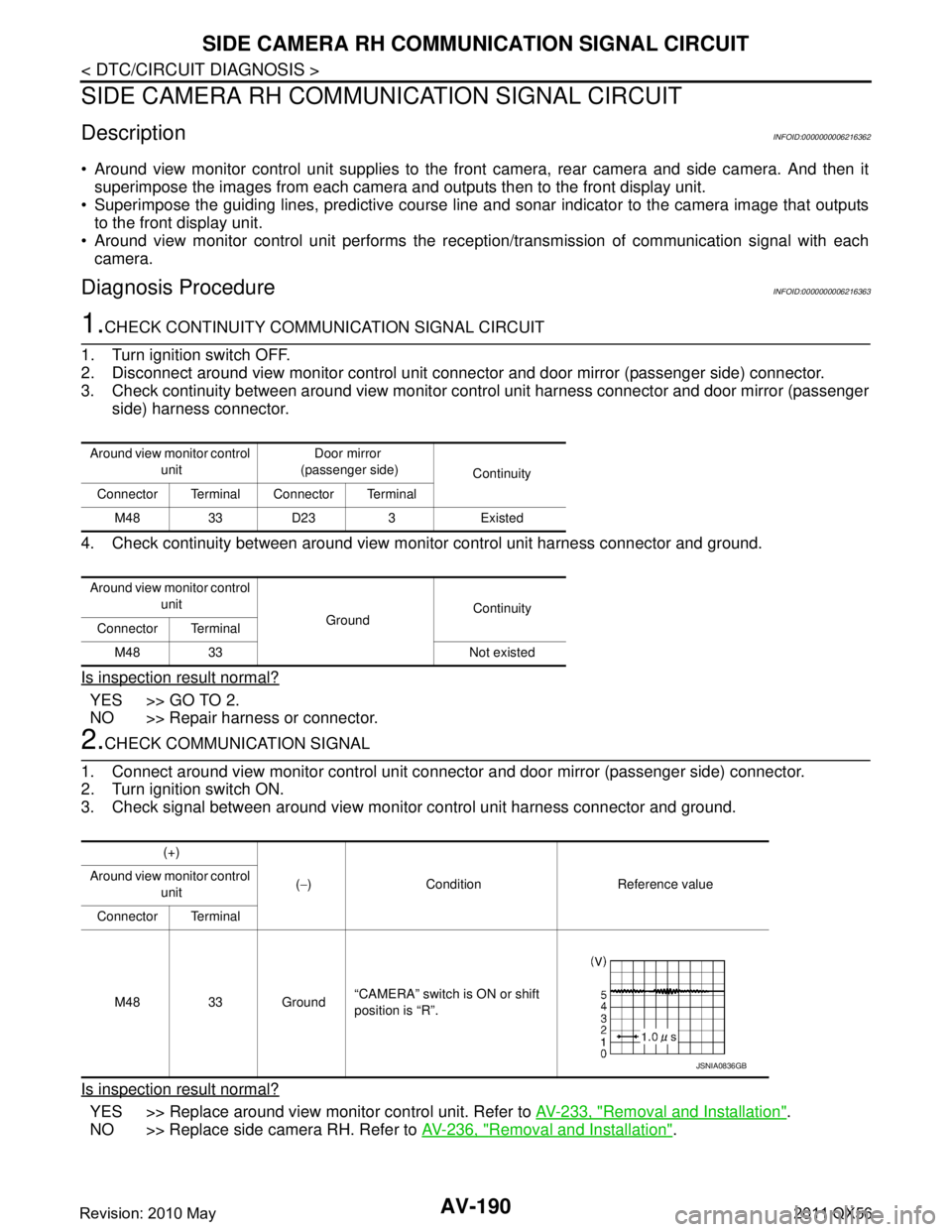
1.CHECK CONTINUITY COMMUNI CATION SIGNAL CIRCUIT
1. Turn ignition switch OFF.
2. Disconnect around view monitor control unit c onnector and door mirror (passenger side) connector.
3. Check continuity between around view monitor c ontrol unit harness connector and door mirror (passenger
side) harness connector.
4. Check continuity between around view m onitor control unit harness connector and ground.
Is inspection result normal?
YES >> GO TO 2.
NO >> Repair harness or connector.
2.CHECK COMMUNICATION SIGNAL
1. Connect around view monitor control unit connector and door mirror (passenger side) connector.
2. Turn ignition switch ON.
3. Check signal between around view monitor control unit harness connector and ground.
Is inspection result normal?
YES >> Replace around view monitor control unit. Refer to AV-233, "Removal and Installation".
NO >> Replace side camera RH. Refer to AV-236, "
Removal and Installation".
Around view monitor control
unit Door mirror
(passenger side) Continuity
Connector Terminal Connector Terminal
M48 33 D23 3 Existed
Around view monitor control unit GroundContinuity
Connector Terminal
M48 33 Not existed
(+)
(− ) Condition Reference value
Around view monitor control
unit
Connector Terminal
M48 33 Ground “CAMERA” switch is ON or shift
position is “R”.
JSNIA0836GB
Revision: 2010 May2011 QX56
Page 339 of 5598

AV
SIDE CAMERA RH IMAGE SIGNAL CIRCUITAV-191
< DTC/CIRCUIT DIAGNOSIS >
C
DE
F
G H
I
J
K L
M B A
O P
SIDE CAMERA RH IM AGE SIGNAL CIRCUIT
DescriptionINFOID:0000000006216364
Around view monitor control unit supplies to the front camera, rear camera and side camera. And then it
superimpose the images from each camera and outputs then to the front display unit.
Superimpose the guiding lines, predictive course line and sonar indicator to the camera image that outputs
to the front display unit.
Around view monitor control unit performs the rec eption/transmission of communication signal with each
camera.
Diagnosis ProcedureINFOID:0000000006216365
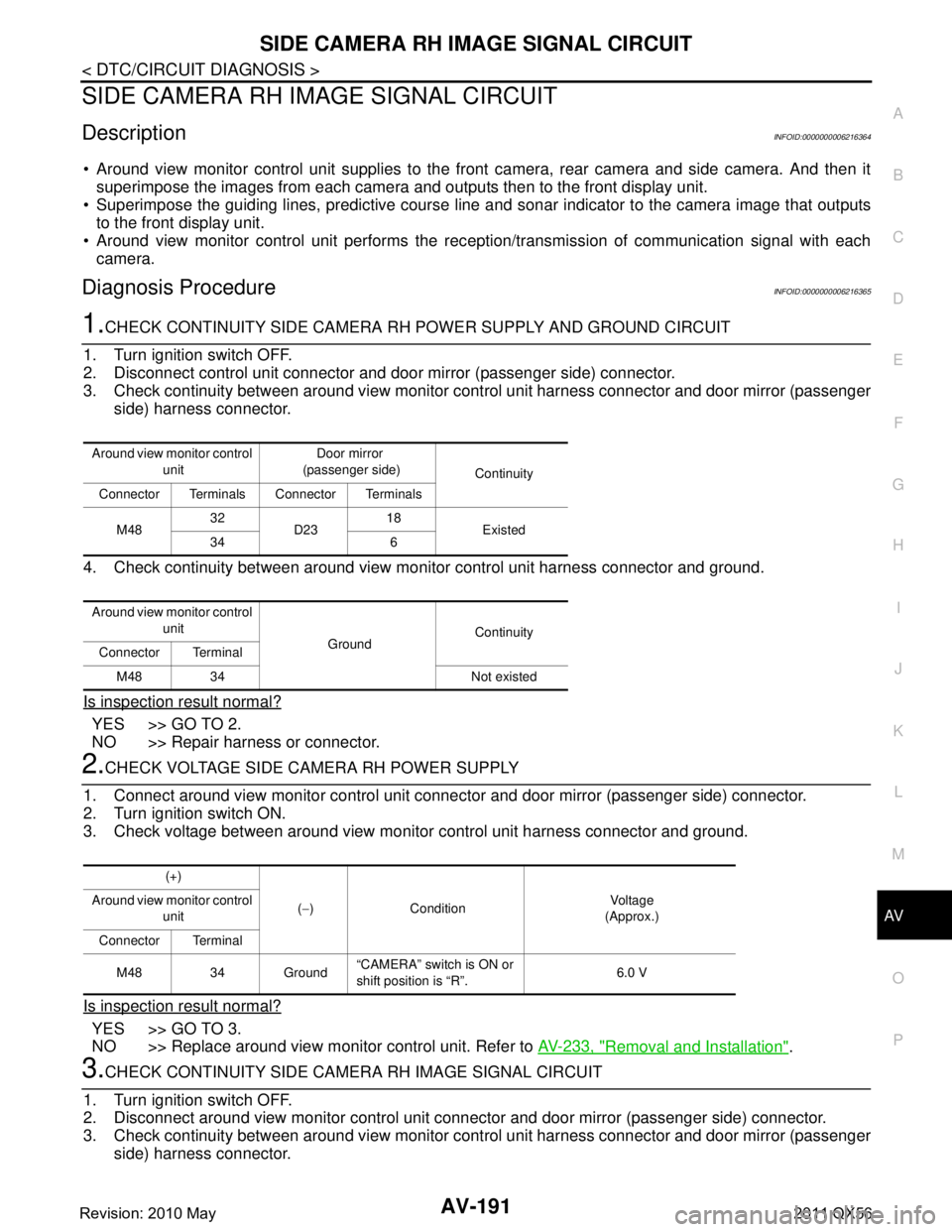
1.CHECK CONTINUITY SIDE CAMERA RH POWER SUPPLY AND GROUND CIRCUIT
1. Turn ignition switch OFF.
2. Disconnect control unit connector and door mirror (passenger side) connector.
3. Check continuity between around view monitor c ontrol unit harness connector and door mirror (passenger
side) harness connector.
4. Check continuity between around view monitor control unit harness connector and ground.
Is inspection result normal?
YES >> GO TO 2.
NO >> Repair harness or connector.
2.CHECK VOLTAGE SIDE CAMERA RH POWER SUPPLY
1. Connect around view monitor control unit connec tor and door mirror (passenger side) connector.
2. Turn ignition switch ON.
3. Check voltage between around view monitor control unit harness connector and ground.
Is inspection result normal?
YES >> GO TO 3.
NO >> Replace around view monitor control unit. Refer to AV-233, "
Removal and Installation".
3.CHECK CONTINUITY SIDE CAMERA RH IMAGE SIGNAL CIRCUIT
1. Turn ignition switch OFF.
2. Disconnect around view monitor control unit connec tor and door mirror (passenger side) connector.
3. Check continuity between around view monitor c ontrol unit harness connector and door mirror (passenger
side) harness connector.
Around view monitor control
unit Door mirror
(passenger side) Continuity
Connector Terminals Connector Terminals
M48 32
D23 18
Existed
34 6
Around view monitor control unit GroundContinuity
Connector Terminal
M48 34 Not existed
(+)
(− ) Condition Vo l ta g e
(Approx.)
Around view monitor control
unit
Connector Terminal
M48 34 Ground “CAMERA” switch is ON or
shift position is “R”.
6.0 V
Revision: 2010 May2011 QX56
Page 340 of 5598

AV-192
< DTC/CIRCUIT DIAGNOSIS >
SIDE CAMERA RH IMAGE SIGNAL CIRCUIT
4. Check continuity between around view monitor control unit harness connector and ground.
Is inspection result normal?
YES >> GO TO 4.
NO >> Repair harness or connector.
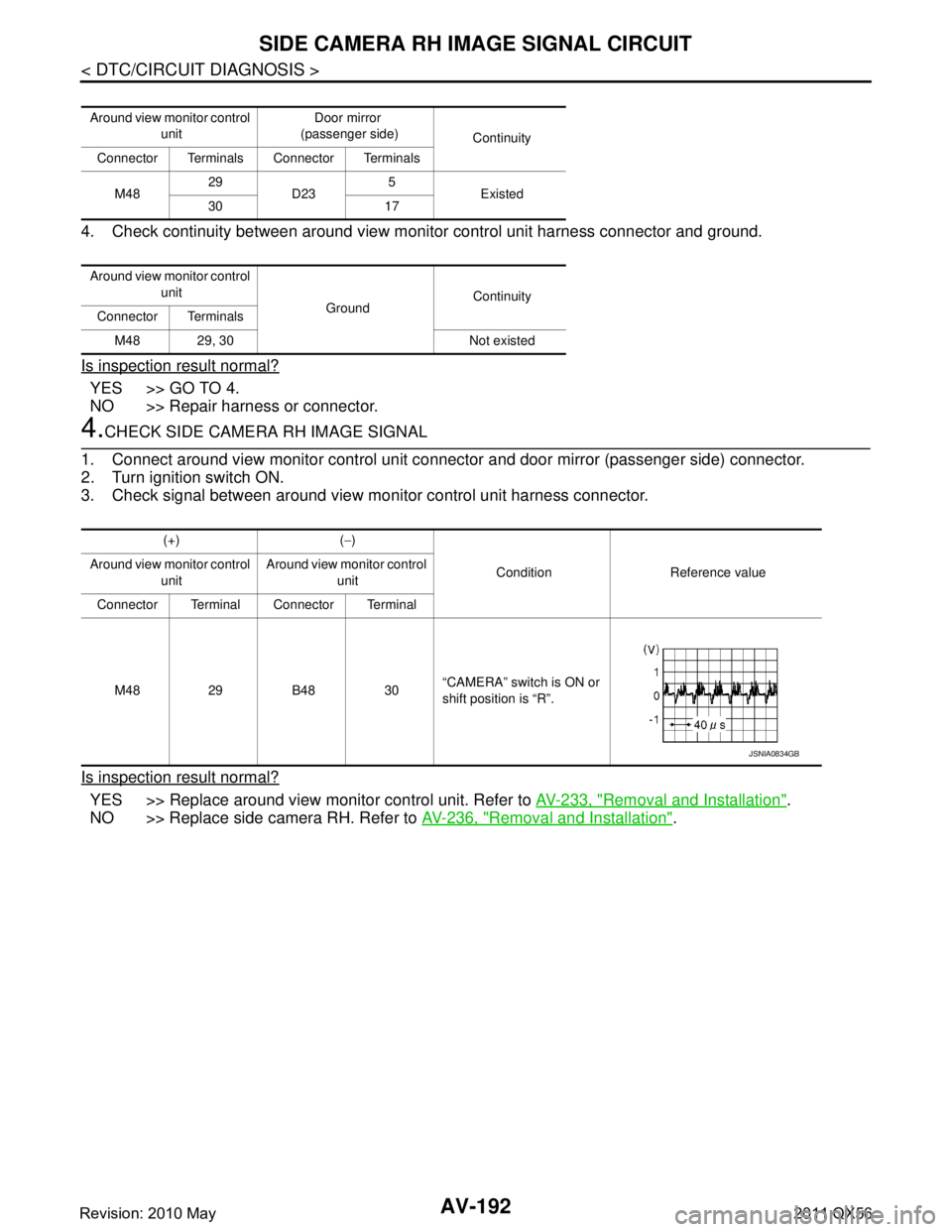
4.CHECK SIDE CAMERA RH IMAGE SIGNAL
1. Connect around view monitor control unit connector and door mirror (passenger side) connector.
2. Turn ignition switch ON.
3. Check signal between around view monitor control unit harness connector.
Is inspection result normal?
YES >> Replace around view monitor control unit. Refer to AV-233, "Removal and Installation".
NO >> Replace side camera RH. Refer to AV-236, "
Removal and Installation".
Around view monitor control
unit Door mirror
(passenger side) Continuity
Connector Terminals Connector Terminals
M48 29
D23 5
Existed
30 17
Around view monitor control unit GroundContinuity
Connector Terminals
M48 29, 30 Not existed
(+) ( −)
Condition Reference value
Around view monitor control
unit Around view monitor control
unit
Connector Terminal Connector Terminal
M48 29 B48 30 “CAMERA” switch is ON or
shift position is “R”.
JSNIA0834GB
Revision: 2010 May2011 QX56