fuel cap release INFINITI QX56 2011 Factory Service Manual
[x] Cancel search | Manufacturer: INFINITI, Model Year: 2011, Model line: QX56, Model: INFINITI QX56 2011Pages: 5598, PDF Size: 94.53 MB
Page 2331 of 5598
![INFINITI QX56 2011 Factory Service Manual
P0420, P0430 THREE WAY CATALYST FUNCTIONEC-307
< DTC/CIRCUIT DIAGNOSIS > [VK56VD]
C
D
E
F
G H
I
J
K L
M A
EC
NP
O
P0420, P0430 THREE WAY CATALYST FUNCTION
DTC LogicINFOID:0000000006217851
DTC DETECTI INFINITI QX56 2011 Factory Service Manual
P0420, P0430 THREE WAY CATALYST FUNCTIONEC-307
< DTC/CIRCUIT DIAGNOSIS > [VK56VD]
C
D
E
F
G H
I
J
K L
M A
EC
NP
O
P0420, P0430 THREE WAY CATALYST FUNCTION
DTC LogicINFOID:0000000006217851
DTC DETECTI](/img/42/57033/w960_57033-2330.png)
P0420, P0430 THREE WAY CATALYST FUNCTIONEC-307
< DTC/CIRCUIT DIAGNOSIS > [VK56VD]
C
D
E
F
G H
I
J
K L
M A
EC
NP
O
P0420, P0430 THREE WAY CATALYST FUNCTION
DTC LogicINFOID:0000000006217851
DTC DETECTION LOGIC
The ECM monitors the switching frequency ratio of air fuel ratio (A/F)
sensor 1 and heated oxygen sensor 2.
A three way catalyst (manifold) with high oxygen storage capacity
will indicate a low switching frequency of heated oxygen sensor 2.
As oxygen storage capacity decr
eases, the heated oxygen sensor 2
switching frequency will increase.
When the frequency ratio of A/F sensor 1 and heated oxygen sensor
2 approaches a specified limit value, the three way catalyst (mani-
fold) malfunction is diagnosed.
DTC CONFIRMATION PROCEDURE
1.INSPECTION START
1. Turn ignition switch OFF and wait at least 10 seconds.
2. Turn ignition switch ON.
3. Turn ignition switch OFF and wait at least 10 seconds.
Will CONSULT-III be used?
YES >> GO TO 2.
NO >> GO TO 6.
2.PERFORM DTC CONFIRMATION PROCEDURE-I
WITH CONSULT-III
TESTING CONDITION:
Do not maintain engine speed for mo re than the specified minutes below.
1. Start engine and warm it up to the normal operating temperature.
2. Turn ignition switch OFF and wait at least 10 seconds.
3. Turn ignition switch ON.
4. Turn ignition switch OFF and wait at least 10 seconds.
5. Start engine and keep the engine speed between 3,500 and 4,000 rpm for at least 1 minute under no load.
6. Let engine idle for 1 minute.
7. Select “DATA MONITOR” mode with CONSULT-III.
8. Check that “COOLAN TEMP/S” indicates more than 70 °C (158 °F).
If not, warm up engine and go to next step when “COOLAN TEMP/S” indication reaches to 70°C (158 °F).
9. Open engine hood.
10. Select “DTC & SRT CONFIRMATION” then “SRT WORK SUPPORT” mode with CONSULT-III.
11. Rev engine between 2,000 and 3,000 rpm and hold it for 3 consecutive minutes then release the acceler-
ator pedal completely.
12. Check the indication of “CATALYST”.
Which is displayed on CONSULT-III screen?
CMPLT >> GO TO 5.
INCMP >> GO TO 3.
PBIB2055E
DTC No. Trouble diagnosis name
(Trouble diagnosis content) DTC detecting condition Possible cause
P0420 TW CATALYST SYS-B1
[Catalyst system efficiency
below threshold (bank 1)]
Three way catalyst (manifold) does not
operate properly.
Three way catalyst (manifold) does not have enough oxygen storage capacity. Three way catalyst (manifold)
Exhaust tube
Intake air leakage
Fuel injector
Fuel injector leakage
Spark plug
Improper ignition timing
P0430
TW CATALYST SYS-B2
[Catalyst system efficiency
below threshold (bank 2)]
Revision: 2010 May2011 QX56
Page 2567 of 5598
PRECAUTIONSEM-5
< PRECAUTION >
C
DE
F
G H
I
J
K L
M A
EM
NP
O
Avoid damaging sliding or mating surfaces. Completely re
move foreign materials such as cloth lint or dust.
Before assembly, oil sliding surfaces well.
Release air within route when refilling after draining engine coolant.
After repairing, start engine and increase engine speed to check engine coolant, fuel, engine oil, and
exhaust gases for leakage.
Parts Requiring Angle TighteningINFOID:0000000006289515
Use angle wrench [SST: KV10112100 (BT8653-A)] for the final tightening of the following engine parts:
- Cylinder head bolts
- Main bearing cap bolts
- Main bearing cap sub bolts
- Connecting rod cap bolts
- Crankshaft pulley bolt (No angle wrench is required as the bolt flange is provided with notches for angletightening)
Ensure thread and seat surfaces are clean and coated with engine oil.
Precaution for Liquid GasketINFOID:0000000006289516
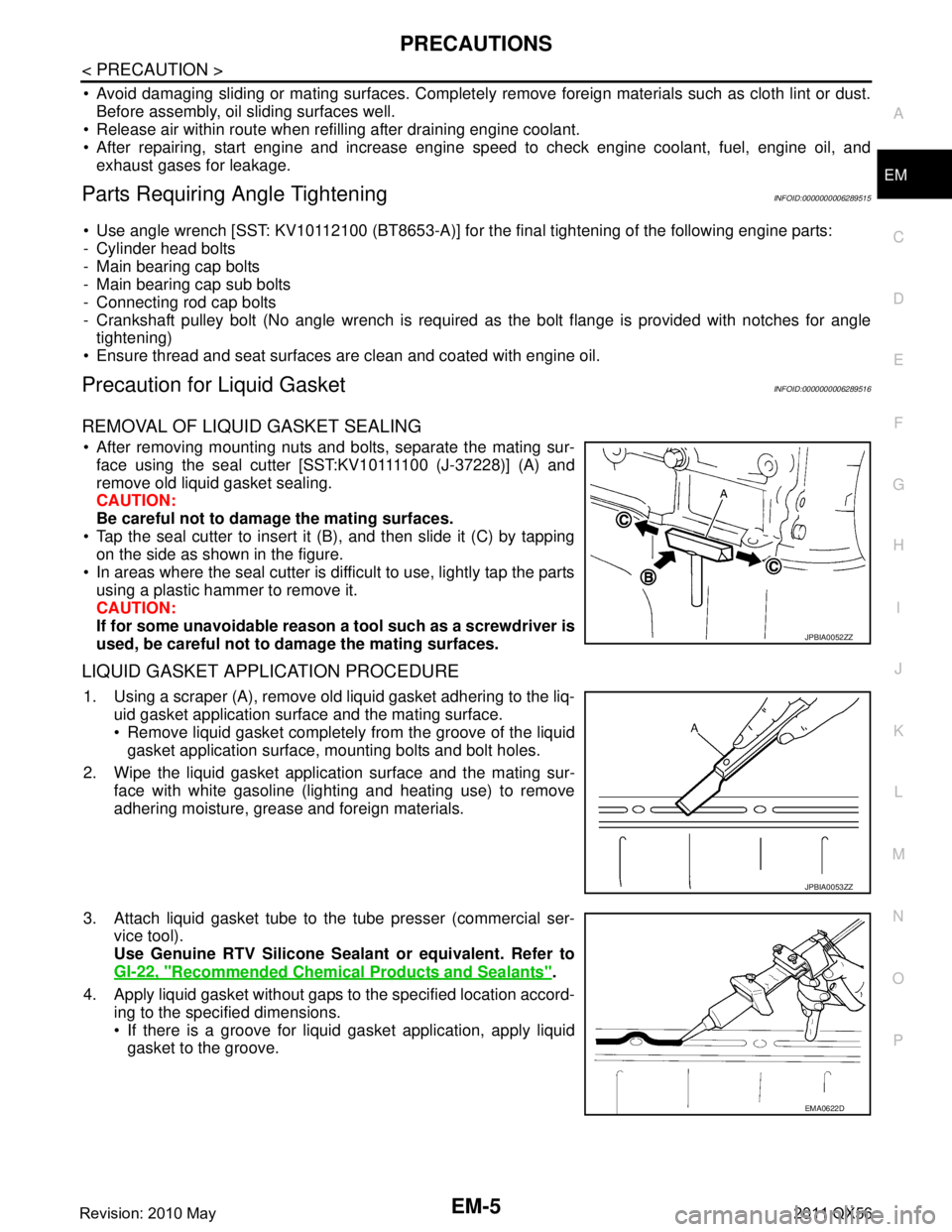
REMOVAL OF LIQUID GASKET SEALING
After removing mounting nuts and bolts, separate the mating sur- face using the seal cutter [SST:KV10111100 (J-37228)] (A) and
remove old liquid gasket sealing.
CAUTION:
Be careful not to damage the mating surfaces.
Tap the seal cutter to insert it (B), and then slide it (C) by tapping on the side as shown in the figure.
In areas where the seal cutter is difficult to use, lightly tap the parts using a plastic hammer to remove it.
CAUTION:
If for some unavoidable reason a tool such as a screwdriver is
used, be careful not to damage the mating surfaces.
LIQUID GASKET APPLICATION PROCEDURE
1. Using a scraper (A), remove old liquid gasket adhering to the liq- uid gasket application surface and the mating surface.
Remove liquid gasket completely from the groove of the liquidgasket application surface, mounting bolts and bolt holes.
2. Wipe the liquid gasket application surface and the mating sur- face with white gasoline (lighting and heating use) to remove
adhering moisture, grease and foreign materials.
3. Attach liquid gasket tube to the tube presser (commercial ser- vice tool).
Use Genuine RTV Silicone Seal ant or equivalent. Refer to
GI-22, "
Recommended Chemical Products and Sealants".
4. Apply liquid gasket without gaps to the specified location accord- ing to the specified dimensions.
If there is a groove for liquid gasket application, apply liquidgasket to the groove.
JPBIA0052ZZ
JPBIA0053ZZ
EMA0622D
Revision: 2010 May2011 QX56
Page 2606 of 5598
EM-44
< REMOVAL AND INSTALLATION >
HIGH PRESSURE FUEL PUMP AND FUEL HOSE
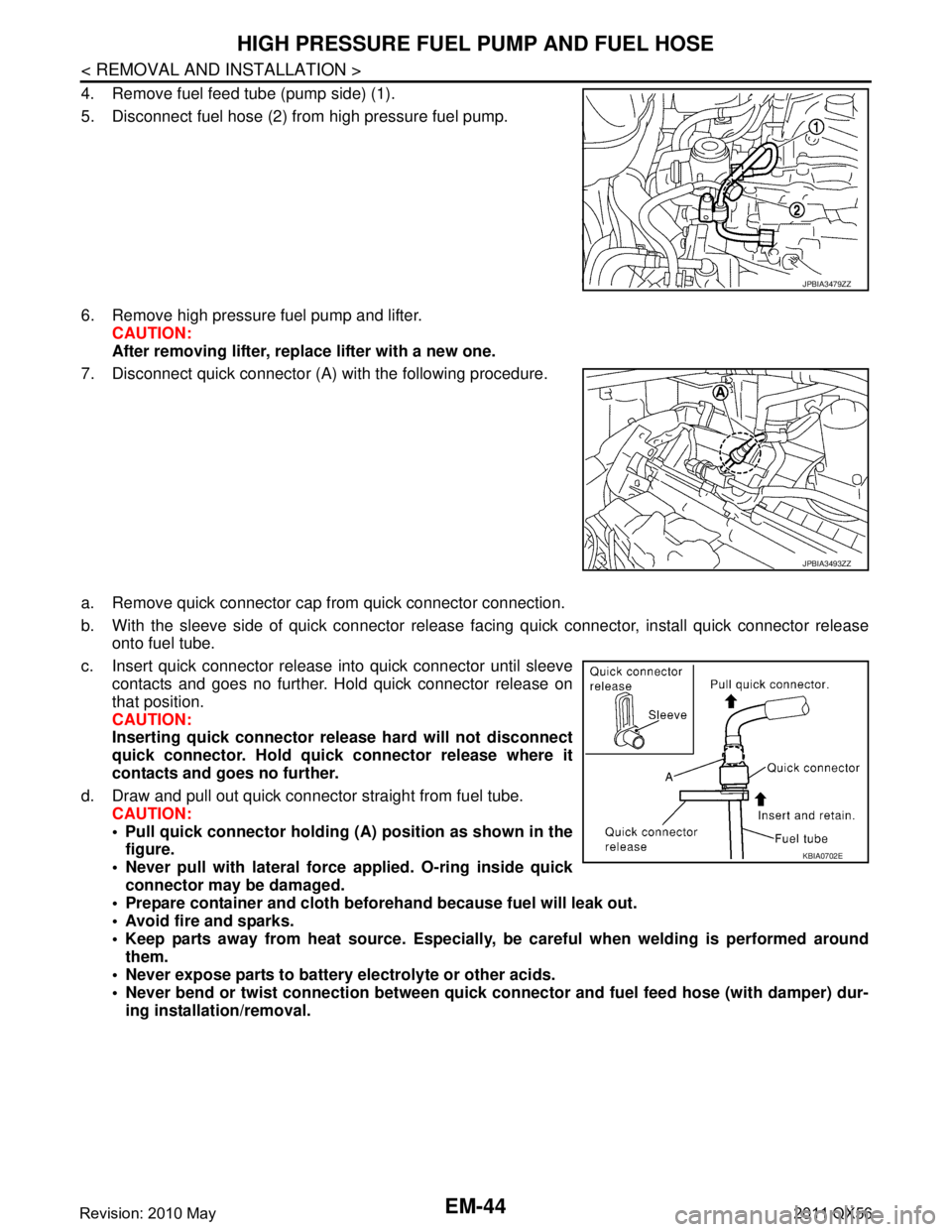
4. Remove fuel feed tube (pump side) (1).
5. Disconnect fuel hose (2) from high pressure fuel pump.
6. Remove high pressure fuel pump and lifter.CAUTION:
After removing lifter, replace lifter with a new one.
7. Disconnect quick connector (A) with the following procedure.
a. Remove quick connector cap from quick connector connection.
b. With the sleeve side of quick connector release facing quick connector, install quick connector release
onto fuel tube.
c. Insert quick connector release into quick connector until sleeve contacts and goes no further. Hold quick connector release on
that position.
CAUTION:
Inserting quick connector re lease hard will not disconnect
quick connector. Hold qui ck connector release where it
contacts and goes no further.
d. Draw and pull out quick connector straight from fuel tube. CAUTION:
Pull quick connector holding (A) position as shown in thefigure.
Never pull with lateral force applied. O-ring inside quick
connector may be damaged.
Prepare container and cloth befo rehand because fuel will leak out.
Avoid fire and sparks.
Keep parts away from heat source. Especially, be careful when welding is performed around
them.
Never expose parts to battery electrolyte or other acids.
Never bend or twist connection between quick c onnector and fuel feed hose (with damper) dur-
ing installation/removal.
JPBIA3479ZZ
JPBIA3493ZZ
KBIA0702E
Revision: 2010 May2011 QX56
Page 2931 of 5598
FL-2
< PRECAUTION >
PRECAUTIONS
PRECAUTION
PRECAUTIONS
General PrecautionsINFOID:0000000006289679
WARNING:
When replacing fuel line parts, be sure to observe the following.
• Put a “CAUTION: FLAMMABLE” sign in the workshop.
Be sure to work in a well ventilate d area and furnish workshop with a CO
2 fire extinguisher.
Never smoke while servicing fuel system. Keep open flames and sparks away from the work area.
CAUTION:
Use gasoline required by the regulations for octane number. Refer to GI-31, "
Fuel".
Before removing fuel line parts, perform out the following procedures:
- Put drained fuel in an explosi on-proof container and put the lid on securely. Keep the container in
safe area.
- Release fuel pressure from the fuel lines. Refer to EC-153, "
Work Procedure".
- Disconnect the battery cable from the negative terminal.
Always replace O-rings with new ones.
Never kink or twist tubes when they are being installed.
Never tighten hose clamps excessi vely to avoid damaging hoses.
After installing tubes, check there is no fuel leakage at connections in the following steps.
- Apply fuel pressure to fuel lin es with turning ignition switch “O N” (with engine stopped). Then check
for fuel leakage at connections.
- Start engine and rev it up and check for fuel leakage at connections.
Use only a genuine NISSAN fuel filler cap as a replacemen t. If an incorrect fuel filler cap is used, the
“MIL” may come on.
For servicing “Evaporative Emission System” parts.
Refer to EC-16, "
Component Parts Location".
Revision: 2010 May2011 QX56
Page 2934 of 5598
FUEL LEVEL SENSOR UNIT, FUEL FILTER AND FUEL PUMP ASSEMBLY
FL-5
< REMOVAL AND INSTALLATION >
C
D E
F
G H
I
J
K L
M A
FL
NP
O
REMOVAL AND INSTALLATION
FUEL LEVEL SENSOR UNIT, FUEL FI
LTER AND FUEL PUMP ASSEMBLY
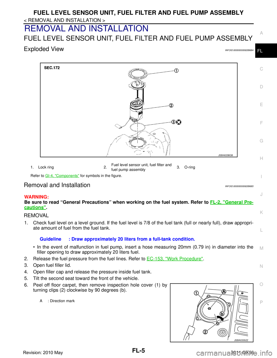
Exploded ViewINFOID:0000000006289684
Removal and InstallationINFOID:0000000006289685
WARNING:
Be sure to read “General Precautions” wh en working on the fuel system. Refer to FL-2, "
General Pre-
cautions".
REMOVAL
1. Check fuel level on a level ground. If the fuel level is 7/8 of the fuel tank (full or nearly full), draw appropri-
ate amount of fuel from the fuel tank.
In the event of malfunction in fuel pump, insert a hose measuring 20mm (0.79 in) in diameter into the
filler opening to draw approximately 20 liters fuel.
2. Release the fuel pressure from the fuel lines. Refer to EC-153, "
Work Procedure".
3. Open fuel filler lid.
4. Open filler cap and release the pressure inside fuel tank.
5. Tilt the second seat toward the front of the vehicle.
6. Peel off floor carpet, then remove inspection hole cover (1) by turning clips (2) clockwise by 90 degrees (b).
1. Lock ring 2. Fuel level sensor unit, fuel filter and
fuel pump assembly3. O-ring
Refer to GI-4, "
Components" for symbols in the figure.
JSBIA0298GB
Guideline : Draw approximately 20 li ters from a full-tank condition.
A : Direction mark
JSBIA0300ZZ
Revision: 2010 May2011 QX56
Page 3686 of 5598
MA-16
< PERIODIC MAINTENANCE >
ENGINE MAINTENANCE
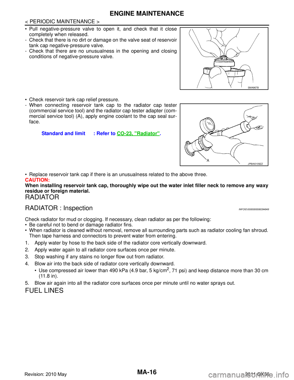
Pull negative-pressure valve to open it, and check that it closecompletely when released.
- Check that there is no dirt or damage on the valve seat of reservoir
tank cap negative-pressure valve.
- Check that there are no unusualness in the opening and closing conditions of negative-pressure valve.
Check reservoir tank cap relief pressure.
- When connecting reservoir tank cap to the radiator cap tester (commercial service tool) and the radiator cap tester adapter (com-
mercial service tool) (A), apply engine coolant to the cap seal sur-
face.
Replace reservoir tank cap if there is an unusualness related to the above three.
CAUTION:
When installing reservoir tank cap, thoroughly wipe out the water inlet filler neck to remove any waxy
residue or foreign material.
RADIATOR
RADIATOR : InspectionINFOID:0000000006394849
Check radiator for mud or clogging. If nec essary, clean radiator as per the following:
Be careful not to bend or damage radiator fins.
When radiator is cleaned without removal, remove all surrounding parts such as radiator cooling fan shroud. Then tape harness and connectors to prevent water from entering.
1. Apply water by hose to the back side of the radiator core vertically downward.
2. Apply water again to all radiator core surfaces once per minute.
3. Stop washing if any stains no longer flow out from radiator.
4. Blow air into the back side of radiator core vertically downward. Use compressed air lower than 490 kPa (4.9 bar, 5 kg/cm
2, 71 psi) and keep distance more than 30 cm
(11.8 in).
5. Blow air again into all the radiator core su rfaces once per minute until no water sprays out.
FUEL LINES
SMA967B
Standard and limit : Refer to CO-23, "Radiator".
JPBIA0109ZZ
Revision: 2010 May2011 QX56