brake light INFINITI QX56 2011 Factory Service Manual
[x] Cancel search | Manufacturer: INFINITI, Model Year: 2011, Model line: QX56, Model: INFINITI QX56 2011Pages: 5598, PDF Size: 94.53 MB
Page 1 of 5598
A
B
D
E
F
G
H
I
J
K
L
M
N
P
O
C
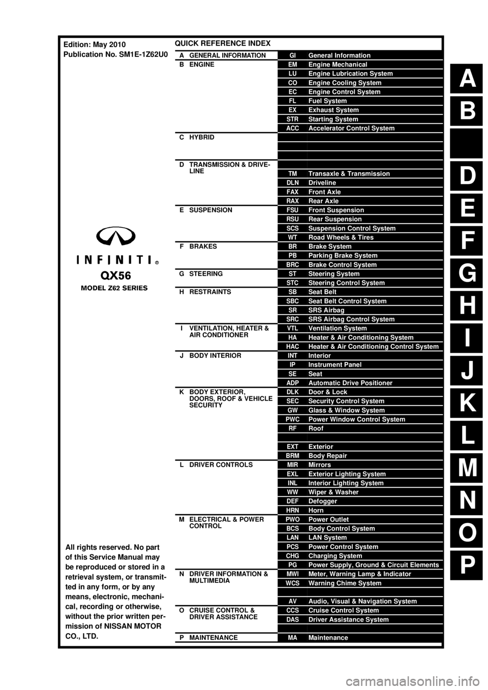
QUICK REFERENCE INDEX
AGENERAL INFORMATIONGIGeneral Information
BENGINEEMEngine Mechanical
LUEngine Lubrication System
COEngine Cooling System
ECEngine Control System
FLFuel System
EXExhaust System
STRStarting System
ACCAccelerator Control System
CHYBRIDHBCHybrid Control System
HBBHybrid Battery System
HBRHybrid Brake System
DTRANSMISSION & DRIVE-
LINECLClutch
TMTransaxle & Transmission
DLNDriveline
FAXFront Axle
RAXRear Axle
ESUSPENSIONFSUFront Suspension
RSURear Suspension
SCSSuspension Control System
WTRoad Wheels & Tires
FBRAKESBRBrake System
PBParking Brake System
BRCBrake Control System
GSTEERINGSTSteering System
STCSteering Control System
HRESTRAINTSSBSeat Belt
SBCSeat Belt Control System
SRSRS Airbag
SRCSRS Airbag Control System
IVENTILATION, HEATER &
AIR CONDITIONERVTLVentilation System
HAHeater & Air Conditioning System
HACHeater & Air Conditioning Control System
JBODY INTERIORINTInterior
IPInstrument Panel
SESeat
ADPAutomatic Drive Positioner
KBODY EXTERIOR,
DOORS, ROOF & VEHICLE
SECURITYDLKDoor & Lock
SECSecurity Control System
GWGlass & Window System
PWCPower Window Control System
RFRoof
HDHood
EXTExterior
BRMBody Repair
LDRIVER CONTROLSMIRMirrors
EXLExterior Lighting System
INLInterior Lighting System
WWWiper & Washer
DEFDefogger
HRNHorn
MELECTRICAL & POWER
CONTROLPWOPower Outlet
BCSBody Control System
LANLAN System
PCSPower Control System
CHGCharging System
PGPower Supply, Ground & Circuit Elements
NDRIVER INFORMATION &
MULTIMEDIAMWIMeter, Warning Lamp & Indicator
WCSWarning Chime System
SNSonar System
AVAudio, Visual & Navigation System
OCRUISE CONTROL &
DRIVER ASSISTANCECCSCruise Control System
DASDriver Assistance System
DMSDrive Mode System
PMAINTENANCEMAMaintenance
All rights reserved. No part
of this Service Manual may
be reproduced or stored in a
retrieval system, or transmit-
ted in any form, or by any
means, electronic, mechani-
cal, recording or otherwise,
without the prior written per-
mission of NISSAN MOTOR
CO., LTD.
Edition: May 2010
Publication No. SM1E-1Z62U0
Page 158 of 5598

AV-10
< SYSTEM DESCRIPTION >
COMPONENT PARTS
Component Description
INFOID:0000000006216214
1. Squawker RH 2. Center speaker 3. Corner sensor front RH
4. Squawker LH 5. Front camera 6. Corner sensor front LH
7. Side camera LH 8. Front door speaker LH 9. Headrest display unit LH
10. Rear door tweeter LH 11. Rear door speaker LH 12. Roof speaker LH
13. Woofer 14. Corner sensor rear LH 15. Satellite radio antenna
16. Rear camera 17. Corner sensor rear RH 18. BOSE amp.
19. Roof speaker RH 20. Antenna amp. 21. Rear door speaker RH
22. Rear door tweeter RH 23. Headrest display unit RH 24. Front door speaker RH
25. Side camera RH and infrared LED
(auxiliary lighting) 26. Front display unit 27. Steering switch
28. Sonar control unit 29. Steering angle sensor 30. Preset switch
31. Around view monitor control unit 32. USB connector 33. Front auxiliary input jacks
34. Rear auxiliary input jacks 35. AV control unit 36. Video distributor
37. Multifunction switch 38. GPS antenna 39. Microphone A. Luggage side lower finisher LH re-
moved condition B.Luggage side lower finisher RH re-
moved condition C.Headlining assembly removed condi-
tion
D. Instrument lower
panel LH removed
condition E. Spiral cable part F. Cluste
r lid C removed condition
G. Within center console H. Instrument panel rear side
Part name Description
AV control unit Integrates hard disk drive (HDD) allowing map data and music data to be stored.
It is the master unit of the MULTI AV system, and it is connected to each control
unit by communication. It operates each system according to communication sig-
nals from the AV control unit.
The AV control unit includes the audio, hands-free phone, navigation, USB con- nection, DVD play and vehicle information functions.
It is connected to ECM and combination meter via CAN communication to obtain
necessary information for the vehicle information function.
It inputs the illumination signals that are required for the front display dimming con- trol.
It inputs the signals for driving status recognition (vehicle speed, reverse and park- ing brake).
The RGB digital image signal and composite image signal are output to front dis-
play unit.
Switches image and sound output to video distributor, inputting image switch sig- nal from headrest display unit via AV communication.
Amp. ON signal and mode change signal transmitted to BOSE amp.
Update of map data is performed with the DVD-ROM.
Front display unit Front display image is controlled by the serial communication from AV control unit.
RGB digital image signal is input from AV control unit.
Composite image signal is input from AV control unit.
Camera image signal is input from around view monitor control unit.
Touch panel function can be operated for each system by touching a display di-
rectly.
Headrest display unit Composite image signal [USB (video data), DVD and auxiliary input images] is in-
put from the video distributor.
It receives the DVD/AUX/USB sound signal from the video distributor, and then transmits it to the headphones.
Outputs image switch signal to video distributor via hard wire, according to rear seat remote controller operation.
Outputs image switch signal to AV control unit via AV communication, according to
rear seat remote controller operation.
Revision: 2010 May2011 QX56
Page 177 of 5598
AV
DIAGNOSIS SYSTEM (AV CONTROL UNIT)AV-29
< SYSTEM DESCRIPTION >
C
DE
F
G H
I
J
K L
M B A
O P
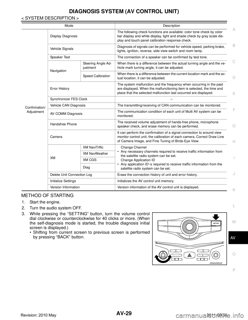
METHOD OF STARTING
1. Start the engine.
2. Turn the audio system OFF.
3. While pressing the “SETTING” button, turn the volume control dial clockwise or counterclockwise for 40 clicks or more. (When
the self-diagnosis mode is start ed, the trouble diagnosis initial
screen is displayed.)
Shifting from current screen to previous screen is performed
by pressing “BACK” button.
Confirmation/
Adjustment Display Diagnosis
The following check functions are available: color tone check by color
bar display and white display, light and shade check by gray scale dis-
play and touch panel calibration response check.
Vehicle Signals Diagnosis of signals can be performed for vehicle speed, parking brake,
lights, ignition, reverse, side view switch and room lamp.
Speaker Test The connection of a speaker can be confirmed by test tone.
Navigation Steering Angle Ad-
justment
When there is a difference between the actual turning angle and the ve-
hicle mark turning angle, it can be adjusted.
Speed Calibration When there is a difference between the current location mark and the ac-
tual location, it can be adjusted.
Error History The system malfunction and the frequency when occurring in the past
are displayed. When the malfunctioning item is selected, the time and
place that the selected malfunction last occurred are displayed.
Synchronizer FES Clock –
Vehicle CAN Diagnosis The transmitting/receiving of CAN communication can be monitored.
AV COMM Diagnosis The communication condition of each unit of Multi AV system can be
monitored.
Handsfree Phone The received volume adjustment of hands-free phone, microphone
speaker check, and erase memory can be performed.
Camera It can perform the confirmation of a signal connection to around view
monitor control unit, the calibration
of each camera, Correct Draw Line
of Camera Image, and Fine Tuning of Birds-Eye View.
XM XM NaviTrffic Change Channel
Any necessary channels required to receive traffic information from the satellite radio system can be set.
Change Application ID
Any application ID'-s required to receive traffic information from the satellite radio system can be set.
XM NavWeather
XM CGS
Diag
Delete Unit Connection Log Erase the connection history of unit and error history.
Initialize Settings Initializes the AV control unit memory.
Version Information Version information of the AV control unit is displayed. Mode Description
JSNIA2993ZZ
Revision: 2010 May2011 QX56
Page 181 of 5598
AV
DIAGNOSIS SYSTEM (AV CONTROL UNIT)AV-33
< SYSTEM DESCRIPTION >
C
DE
F
G H
I
J
K L
M B A
O P
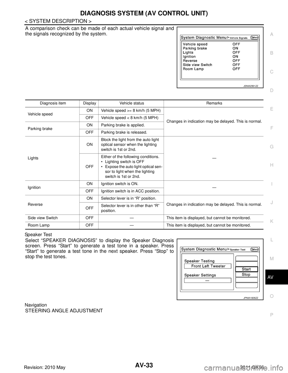
A comparison check can be made of each actual vehicle signal and
the signals recognized by the system.
Sp ea ke r Tes t
Select “SPEAKER DIAGNOSIS” to display the Speaker Diagnosis
screen. Press “Start” to generate a test tone in a speaker. Press
“Start” to generate a test tone in the next speaker. Press “Stop” to
stop the test tones.
Navigation
STEERING ANGLE ADJUSTMENT
JSNIA2991ZZ
Diagnosis item Display Vehicle status Remarks
Vehicle speed ON Vehicle speed >= 8 km/h (5 MPH)
Changes in indication may be delayed. This is normal.
OFF Vehicle speed < 8 km/h (5 MPH)
Parking brake ON Parking brake is applied.
OFF Parking brake is released.
Lights ON
Block the light from the auto light
optical sensor when the lighting
switch is 1st or 2nd.
—
OFF Either of the following conditions.
Lighting switch is OFF
Expose the auto light optical sen-
sor to light when the lighting
switch is 1st or 2nd.
Ignition ON Ignition switch is ON.
—
OFF Ignition switch is in ACC position.
Reverse ON Selector lever is in “R” position.
Changes in indication may be delayed. This is normal.
OFF Selector lever is in other than “R”
position.
Side view Switch OFF — This item is displayed, but cannot be monitored.
Room Lamp OFF — This item is displayed, but cannot be monitored.
JPNIA1828ZZ
Revision: 2010 May2011 QX56
Page 190 of 5598

AV-42
< SYSTEM DESCRIPTION >
DIAGNOSIS SYSTEM (AV CONTROL UNIT)
DATA MONITOR
ALL SIGNALS
Displays the status of the following vehicle signals inputted into the AV control unit.
For each signal, actual signal can be compared with the condition recognized on the system.
AV COMM CIRCUIT [U1300]
SWITCH CONN [U1240]When either one of the following items are
detected:
multifunction switch power supply and
ground circuits are malfunctioning.
AV communication circuits between AV
control unit and multifunction switch are
malfunctioning. Multifunction switch power supply and
ground circuits.
AV communication circuits between AV control unit and multifunction switch.
AV COMM CIRCUIT [U1300]
AROUND CAMERA CONN [U125B] When either one of the following items are
detected:
around view monitor control unit power
supply and ground circuits are malfunc-
tioning.
AV communication circuits between AV control unit and around view monitor
control unit are malfunctioning. Around view monitor control unit power
supply and ground circuits.
AV communication circuits between AV control unit and around view monitor
control unit.
AV COMM CIRCUIT [U1300]
SONAR CONN [U125C] When either one of the following items are
detected:
sonar control unit power supply and
ground circuits are malfunctioning.
AV communication circuits between AV control unit and sonar control unit are
malfunctioning. Sonar control unit power supply and
ground circuits.
AV communication circuits between AV control unit and sonar control unit.
AV COMM CIRCUIT [U1300]
SWITCH CONN [U1240]
SONAR CONN [U125C]
AROUND CAMERA CONN [U125B] AV communication circuits between AV
control unit and multifunction switch are
malfunctioning.AV communication circuits between AV
control unit and multifunction switch.
AV COMM CIRCUIT [U1300]
SWITCH CONN [U1240]
SONAR CONN [U125C]
AROUND CAMERA CONN [U125B]
VIDEO DIST CONN [U1246] Error item Description Possible malfunction factor/Action to take
Display Item Display Vehicle status Remarks
VHCL SPD SIG On Vehicle speed >= 8 km/h (5 MPH)
Changes in indication may be delayed. This is
normal.
Off Vehicle speed < 8 km/h (5 MPH)
PKB SIG On Parking brake is applied.
Off Parking brake is released.
ILLUM SIG On
Block the light from the auto light op-
tical sensor when the lighting switch
is 1st or 2nd.
—
Off Either of the following conditions.
Lighting switch is OFF
Expose the auto light optical sen-
sor to light when the lighting switch
is 1st or 2nd.
IGN SIG On Ignition switch is ON
Off Ignition switch is in ACC position
REV SIG On Selector lever is in R position
Changes in indication may be delayed. This is
normal.
Off Selector lever is in any position other
than R
Revision: 2010 May2011 QX56
Page 199 of 5598
AV
AV CONTROL UNITAV-51
< ECU DIAGNOSIS INFORMATION >
C
DE
F
G H
I
J
K L
M B A
O P
ECU DIAGNOSIS INFORMATION
AV CONTROL UNIT
Reference ValueINFOID:0000000006216225
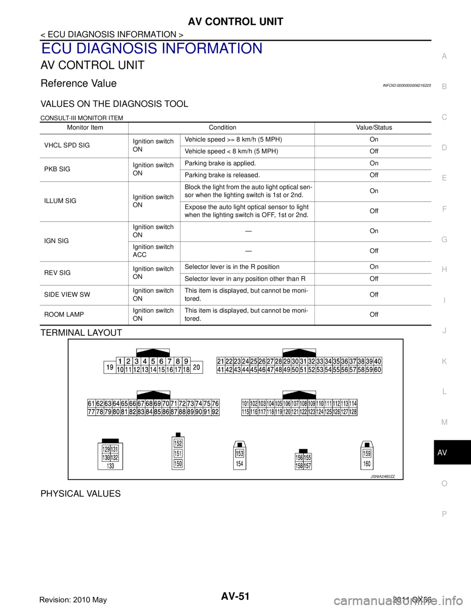
VALUES ON THE DIAGNOSIS TOOL
CONSULT-III MONITOR ITEM
TERMINAL LAYOUT
PHYSICAL VALUES
Monitor Item Condition Value/Status
VHCL SPD SIG Ignition switch
ONVehicle speed >= 8 km/h (5 MPH) On
Vehicle speed < 8 km/h (5 MPH) Off
PKB SIG Ignition switch
ONParking brake is applied. On
Parking brake is released. Off
ILLUM SIG Ignition switch
ONBlock the light from the auto light optical sen-
sor when the lighting switch is 1st or 2nd.
On
Expose the auto light optical sensor to light
when the lighting switch is OFF, 1st or 2nd. Off
IGN SIG Ignition switch
ON
—On
Ignition switch
ACC —Off
REV SIG Ignition switch
ONSelector lever is in the R position On
Selector lever in any position other than R Off
SIDE VIEW SW Ignition switch
ONThis item is displayed, but cannot be moni-
tored.
Off
ROOM LAMP Ignition switch
ONThis item is displayed, but cannot be moni-
tored.
Off
JSNIA2480ZZ
Revision: 2010 May2011 QX56
Page 413 of 5598

BCS
DIAGNOSIS SYSTEM (BCM)BCS-25
< SYSTEM DESCRIPTION >
C
DE
F
G H
I
J
K L
B A
O P
N
SELF-DIAG RESULT
Refer to
BCS-57, "DTCIndex".
DATA MONITOR
SHORT CRANKING OUTPUT Starter motor can operate during the times below
70 msec
100 msec
200 msec
CONFIRM KEY FOB ID It can be checked wh ether Intelligent Key ID code is registered or not in this mode
AUTO LOCK SET Auto door lock operation time can be changed in this mode
MODE 1: OFF
MODE 2: 30 sec
MODE 3: 1 minute
MODE 4: 2 minutes
MODE 5: 3 minutes
MODE 6: 4 minutes
MODE 7: 5 minutes
HORN WITH KEYLESS LOCK Horn reminder function mode by Intelligent Key button can be selected from the following with
this mode
On: Operate
Off: Non-operation
PW DOWN SET Unlock button pressing time on Intelligent Key button can be selected from the following with
this mode
MODE 1: 3 sec
MODE 2: Non-operation
MODE 3: 5 sec
WELCOME LIGHT SELECT Welcome light function mode can be selected from the following with this mode
Puddle/Outside Handle
Room lamp
Head & Tail Lamps (this item is displayed, but cannot be used)
Heart Beat
WELCOME LIGHT OP SET Welcome light function mode can be changed to operation with this mode
On: Operate
Off: Non-operation
Monitor item Description
Monitor Item Condition
REQ SW -DR Indicates [On/Off] condition of door request switch (driver side)
REQ SW -AS Indicates [On/Off] condition of door request switch (passenger side)
REQ SW -BD/TR Indicates [On/Off] condition of back door request switch
PUSH SW Indicates [On/Off] condition of push-button ignition switch
CLUTCH SW NOTE:
This item is displayed, but cannot be monitored
BRAKE SW 1 Indicates [On/Off]* conditio n of stop lamp switch power supply
BRAKE SW 2 Indicates [On/Off] co ndition of stop lamp switch
DETE/CANCL SW Indicates [On/Off] condition of P position
SFT PN/N SW Indicates [On/Off] condition of P or N position
S/L -LOCK Indicates [On/Off] condition of steering lock unit (LOCK)
S/L -UNLOCK Indicates [On/Off] condition of steering lock unit (UNLOCK)
S/L RELAY -F/B Indicates [On/Off] condition of steering lock relay
UNLK SEN -DR Indicates [On/Off] condition of driver door UNLOCK status
PUSH SW -IPDM Indicates [On/Off] condition of push-button ignition switch
IGN RLY1 -F/B Indicates [On/Off] condition of ignition relay 1
DETE SW -IPDM Indicates [On/Off] condition of P position
Revision: 2010 May2011 QX56
Page 423 of 5598

BCS
BCM
BCS-35
< ECU DIAGNOSIS INFORMATION >
C
D E
F
G H
I
J
K L
B A
O P
N
OPTICAL SENSOR
NOTE:
The item is indicated, but not monitored. Off
RAIN SENSOR No rain (or very light rain) Off
Light rain
LOW
Heavy rain HIGH
When liquid is splashed on the front window SPLSH
Rain sensor internal error NG
REQ SW -DR Driver door request switch is not pressed Off
Driver door request switch is pressed On
REQ SW -AS Passenger door request switch is not pressed Off
Passenger door request switch is pressed On
REQ SW -RR NOTE:
The item is indicated, but not monitored.
Off
REQ SW -RL NOTE:
The item is indicated, but not monitored. Off
REQ SW -BD/TR Back door request switch is not pressed Off
Back door request switch is pressed On
PUSH SW Push-button ignition switch (push switch) is not pressed Off
Push-button ignition switch (push switch) is pressed On
CLUCH SW NOTE:
The item is indicated, but not monitored. Off
BRAKE SW 1 The brake pedal is not depressed Off
The brake pedal is depressed On
BRAKE SW 2 The brake pedal is depressed when No. 7 fuse is blown Off
The brake pedal is not depressed when No. 7 fuse is blown, or No. 7 fuse
is normal
On
DETE/CANCL SW Selector lever in P position Off
Selector lever in any position other than P On
SFT PN/N SW Selector lever in any position other than P and N Off
Selector lever in P or N position On
S/L -LOCK Steering is locked Off
Steering is unlocked On
S/L -UNLOCK Steering is unlocked Off
Steering is locked On
S/L RELAY-F/B Steering is unlocked Off
Steering is locked On
UNLK SEN -DR Driver door is locked Off
Driver door is unlocked On
PUSH SW -IPDM Push-button ignition switch (push-switch) is not pressed Off
Push-button ignition switch (push-switch) is pressed On
IGN RLY1 -F/B Ignition switch in OFF or ACC position Off
Ignition switch in ON position On
DETE SW -IPDM Selector lever in any position other than P Off
Selector lever in P position On
SFT PN -IPDM Selector lever in any position other than P and N Off
Selector lever in P or N position On
Monitor Item Condition Value/Status
Revision: 2010 May2011 QX56
Page 429 of 5598
BCS
BCM
BCS-41
< ECU DIAGNOSIS INFORMATION >
C
D E
F
G H
I
J
K L
B A
O P
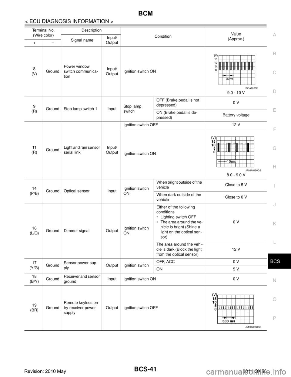
N8
(V) Ground Power window
switch communica-
tion Input/
Output Ignition switch ON
9.0 - 10 V
9
(R) Ground Stop lamp switch 1 Input Stop lamp
switchOFF (Brake pedal is not
depressed)
0 V
ON (Brake pedal is de-
pressed) Battery voltage
11
(R) Ground
Light and rain sensor
serial link Input/
Output Ignition switch OFF 12 V
Ignition switch ON
8.0 - 9.0 V
14
(P/B) Ground Optical sensor Input Ignition switch
ONWhen bright outside of the
vehicle
Close to 5 V
When dark outside of the
vehicle Close to 0 V
16
(L/O) Ground Dimmer signal Output Ignition switch
ONEither of the following
conditions
Lighting switch OFF
The area around the ve-
hicle is bright (Shine a
light on the optical sen-
sor) 0 V
The area around the vehi-
cle is dark (Block the light
from the optical sensor) 12 V
17
(Y/G) Ground Sensor power sup-
ply
Output Ignition switch OFF, ACC 0 V
ON 5 V
18
(B/Y) Ground Receiver and sensor
ground Input Ignition switch ON 0 V
19
(BR) Ground Remote keyless en-
try receiver power
supply
Output Ignition switch OFF
Terminal No.
(Wire color) Description
Condition Va l u e
(Approx.)
Signal name Input/
Output
+ −
PKIA7023E
JPMIA0156GB
JMKIA3838GB
Revision: 2010 May2011 QX56
Page 474 of 5598
BR-4
< PRECAUTION >
PRECAUTIONS
5. When the repair work is completed, re-connect both battery cables. With the brake pedal released, turn
the push-button ignition switch from ACC position to ON position, then to LOCK position. (The steering
wheel will lock when the push-button igniti on switch is turned to LOCK position.)
6. Perform self-diagnosis check of all control units using CONSULT-III.
Precaution for Procedure without Cowl Top CoverINFOID:0000000006228173
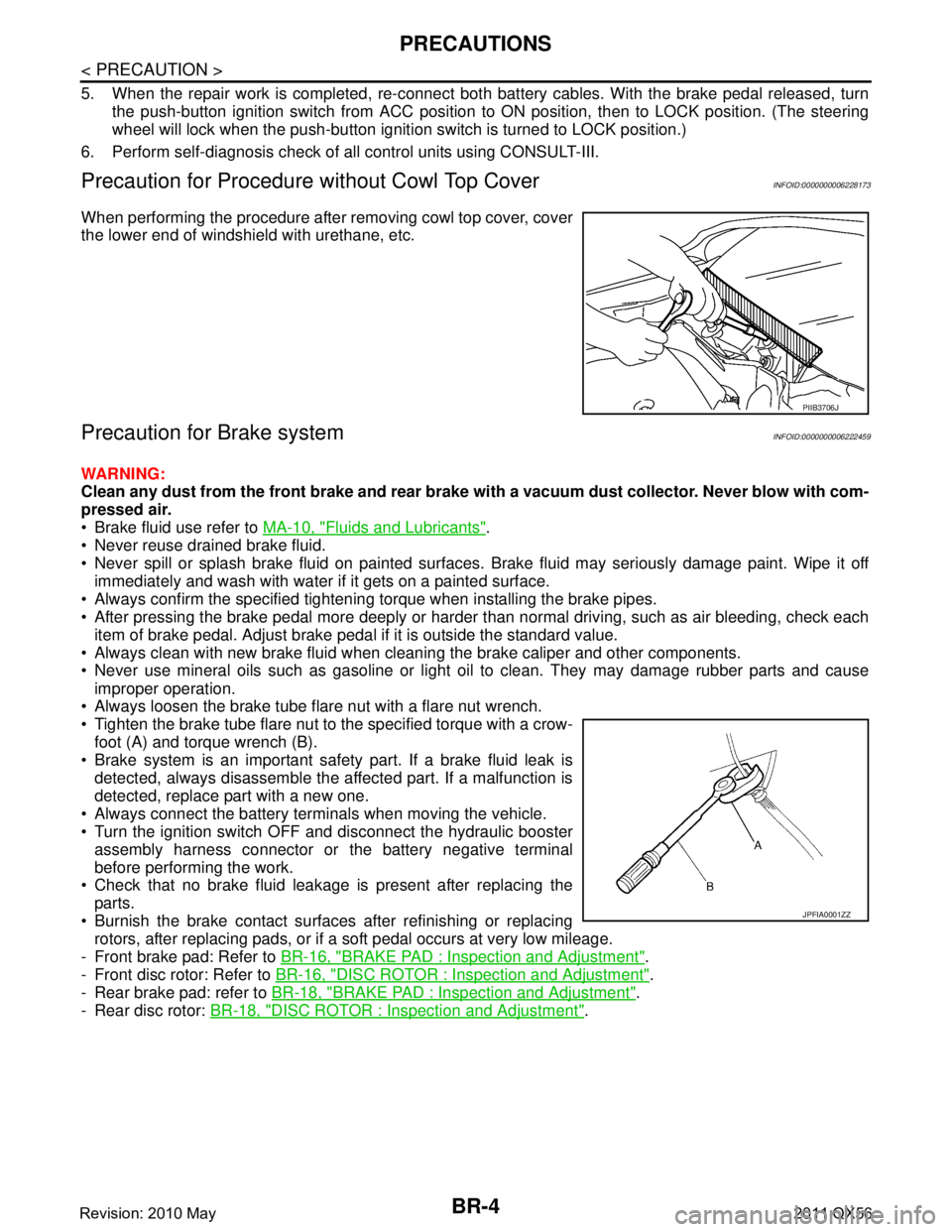
When performing the procedure after removing cowl top cover, cover
the lower end of windshield with urethane, etc.
Precaution for Brake systemINFOID:0000000006222459
WARNING:
Clean any dust from the front brake and rear brake wi th a vacuum dust collector. Never blow with com-
pressed air.
Brake fluid use refer to MA-10, "
Fluids and Lubricants".
Never reuse drained brake fluid.
Never spill or splash brake fluid on painted surfaces. Brake fluid may seriously damage paint. Wipe it off
immediately and wash with water if it gets on a painted surface.
Always confirm the specified tightening torque when installing the brake pipes.
After pressing the brake pedal more deeply or harder t han normal driving, such as air bleeding, check each
item of brake pedal. Adjust brake pedal if it is outside the standard value.
Always clean with new brake fluid when cleaning the brake caliper and other components.
Never use mineral oils such as gasoline or light oil to clean. They may damage rubber parts and cause
improper operation.
Always loosen the brake tube flar e nut with a flare nut wrench.
Tighten the brake tube flare nut to the specified torque with a crow-
foot (A) and torque wrench (B).
Brake system is an important safety part. If a brake fluid leak is detected, always disassemble the affected part. If a malfunction is
detected, replace part with a new one.
Always connect the battery terminals when moving the vehicle.
Turn the ignition switch OFF and disconnect the hydraulic booster assembly harness connector or the battery negative terminal
before performing the work.
Check that no brake fluid leakage is present after replacing the
parts.
Burnish the brake contact surfaces after refinishing or replacing rotors, after replacing pads, or if a soft pedal occurs at very low mileage.
- Front brake pad: Refer to BR-16, "
BRAKE PAD : Inspection and Adjustment".
- Front disc rotor: Refer to BR-16, "
DISC ROTOR : Inspection and Adjustment".
- Rear brake pad: refer to BR-18, "
BRAKE PAD : Inspection and Adjustment".
- Rear disc rotor: BR-18, "
DISC ROTOR : Inspection and Adjustment".
PIIB3706J
JPFIA0001ZZ
Revision: 2010 May2011 QX56