dimensions INFINITI QX56 2011 Factory Service Manual
[x] Cancel search | Manufacturer: INFINITI, Model Year: 2011, Model line: QX56, Model: INFINITI QX56 2011Pages: 5598, PDF Size: 94.53 MB
Page 164 of 5598
AV-16
< SYSTEM DESCRIPTION >
SYSTEM
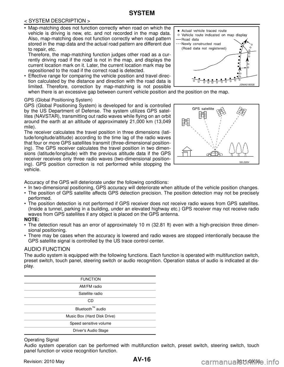
Map-matching does not function correctly when road on which thevehicle is driving is new, etc. and not recorded in the map data.
Also, map-matching does not function correctly when road pattern
stored in the map data and the actual road pattern are different due
to repair, etc.
Therefore, the map-matching func tion judges other road as a cur-
rently driving road if the road is not in the map, and displays the
current location mark on it. Later, the current location mark may be
repositioned to the road if t he correct road is detected.
Effective range for comparing the vehicle position and travel direc- tion calculated by the distance and direction with the road data is
limited. Therefore, correction by map-matching is not possible
when there is an excessive gap between current vehicle position and the position on the map.
GPS (Global Positioning System)
GPS (Global Positioning System) is developed for and is controlled
by the US Department of Defens e. The system utilizes GPS satel-
lites (NAVSTAR), transmitting out radio waves while flying on an orbit
around the earth at an altitude of approximately 21,000 km (13,049
mile).
The receiver calculates the travel position in three dimensions (lati-
tude/longitude/altitude) according to the time lag of the radio waves
that four or more GPS satellites transmit (three-dimensional position-
ing). The GPS receiver calculates the travel position in two dimen-
sions (latitude/longitude) with the previous altitude data if the GPS
receiver receives only three radio waves (two-dimensional position-
ing). GPS position correction is not performed while stopping the
vehicle.
Accuracy of the GPS will deteriorate under the following conditions:
In two-dimensional positioning, GPS accuracy will det eriorate when altitude of the vehicle position changes.
The position of GPS satellite affects GPS detection pr ecision. The position detection may not be precisely
performed.
The position detection is not performed if GPS receiver does not receive radio waves from GPS satellites.
(Inside a tunnel, parking in a building, under an elevat ed highway etc.) GPS receiver may not receive radio
waves from GPS satellites if any object is placed on the GPS antenna.
NOTE:
The detection result has an error of approximately 10 m (32.81 ft) even with a high-precision three dimen- sional positioning.
There may be cases when the accuracy is lowered and radio waves are stopped intentionally because the GPS satellite signal is controlled by the US trace control center.
AUDIO FUNCTION
The audio system is equipped with the following functions. Each function is operated with multifunction switch,
preset switch, touch panel, steering switch or audio rec ognition. Operation status of audio is indicated at dis-
play.
Operating Signal
Audio system operation can be performed with multifuncti on switch, preset switch, steering switch, touch
panel function or voice recognition function.
JSNIA0180GB
SEL526V
FUNCTION
AM/FM radio
Satellite radio CD
Bluetooth
™ audio
Music Box (Hard Disk Drive) Speed sensitive volumeDriver's Audio Stage
Revision: 2010 May2011 QX56
Page 723 of 5598

BRM-48
< SERVICE DATA AND SPECIFICATIONS (SDS)
BODY ALIGNMENT
SERVICE DATA AND SPECIFICATIONS (SDS)
BODY ALIGNMENT
Body Center MarksINFOID:0000000006248507
A mark is placed on each part of the body to indicate the vehicle center. When repairing the vehicle frame
(members, pillars, etc.) damaged by an accident which it enables more accurate and effective repair by using
these marks together with body alignment specifications.
Unit: mm (in)
DescriptionINFOID:0000000006248508
All dimensions indicated in the figures are actual.
When using a tracking gauge, adjust both pointers to equal length. Then check the pointers and gauge itself
to make sure there is no free play.
: Vehicle front
Points Portion Marks
A Upper dash Hole 7 ×12 (0.28 ×0.47)
B Cowl top Embossment
C Rear roof Indent
JSKIA1895ZZ
Revision: 2010 May2011 QX56
Page 724 of 5598

BODY ALIGNMENTBRM-49
< SERVICE DATA AND SPECIFICATIONS (SDS)
C
DE
F
G H
I
J
L
M A
B
BRM
N
O P
When a measuring tape is used, check to be su re there is no elongation, twisting or bending.
Measurements should be taken at the center of the mounting holes.
An asterisk (*) following the value at the measuring poi nt indicates that the measuring point on the other side
is symmetrically the same value.
The coordinates of the measurement points are the distances measured from the standard line of ″X ″, ″Y ″
and ″Z ″.
″Z ″: Imaginary base line [300 mm (11.81 in) below datum line ( ″0Z ″ at design plan)]
Engine CompartmentINFOID:0000000006248509
Measurement
Dimensions marked with ″*″ indicate symmetrically identical dimensions on both the right and left hand of the
vehicle.
1. Vehicle center 2. Front axle center 3. Imaginary base line
JSKIA0073GB
Revision: 2010 May2011 QX56
Page 727 of 5598

BRM-52
< SERVICE DATA AND SPECIFICATIONS (SDS)
BODY ALIGNMENT
Underbody
INFOID:0000000006248510
Measurement
Dimensions marked with ″*″ indicate symmetrically identical dimensions on both the right and left hand of the
vehicle.
The following figure shows a bottom view and a side view of the vehicle.
JSKIA1948GB
Revision: 2010 May2011 QX56
Page 729 of 5598

BRM-54
< SERVICE DATA AND SPECIFICATIONS (SDS)
BODY ALIGNMENT
Passenger Compartment
INFOID:0000000006248511
Measurement
Dimensions marked with ″*″ indicate symmetrically identical dimensions on both the right and left hand of the
vehicle.
«The others»
c −
289.6
( − 11 . 4 0 2 ) 0.2
(0.008) 305.8
(12.039) Hole
φ19 (0.75) J, j ±
501.7
( ± 19.752) 3750.7
(147.665) 378.4
(14.898) Hole
φ8 (0.31)
D, d ±
461.8
( ± 18.181) 807.5
(31.791) 104.1
(4.098) Hole
φ10 (0.39) K, k ±
561.6
( ± 22.110) 4050.0
(159.449) 337.0
(13.268) Hole
φ15 (0.59)
E, e ±
592.0
( ± 23.307) 1320.0
(51.968) 98.3
(3.870) Hole 20
×8
(0.79 ×0.31) M, m
±
498.4
( ± 19.622) -29.6
(-1.165) 519.2
(20.441) Hole
φ70 (2.76)
Points
Coordinates
Remarks Points Coordinates
Remarks
XYZ XYZ
Unit: mm (in)
JSKIA1900GB
Revision: 2010 May2011 QX56
Page 731 of 5598
BRM-56
< SERVICE DATA AND SPECIFICATIONS (SDS)
BODY ALIGNMENT
Unit: mm (in)
Rear BodyINFOID:0000000006248512
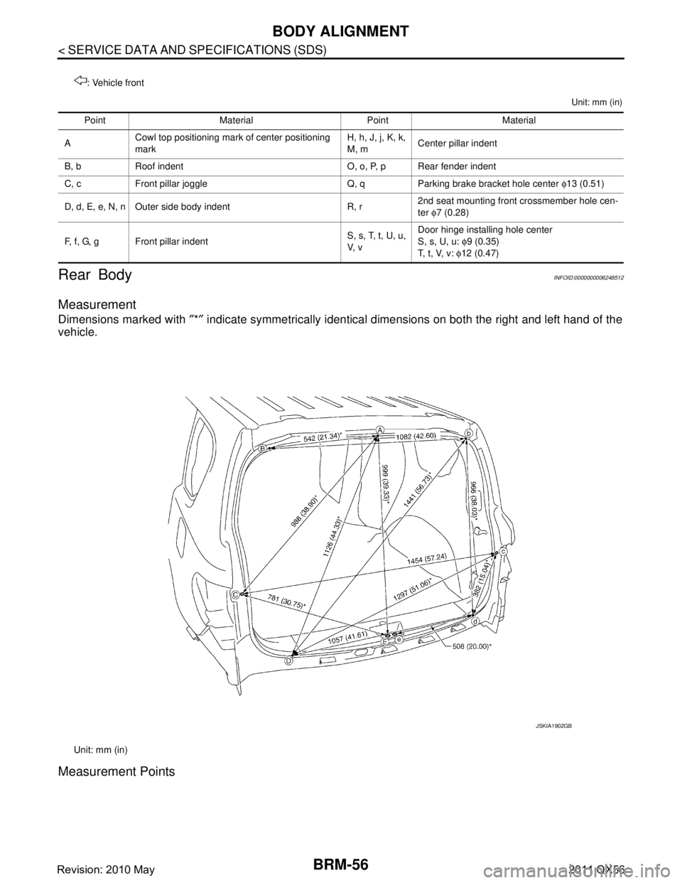
Measurement
Dimensions marked with ″*″ indicate symmetrically identical dimensions on both the right and left hand of the
vehicle.
Measurement Points
: Vehicle front
Point Material Point Material
A Cowl top positioning mark of center positioning
mark H, h, J, j, K, k,
M, m
Center pillar indent
B, b Roof indent O, o, P, p Rear fender indent
C, c Front pillar joggle Q, q Parking brake bracket hole center φ13 (0.51)
D, d, E, e, N, n Outer side body indent R, r 2nd seat mounting front crossmember hole cen-
ter
φ7 (0.28)
F, f, G, g Front pillar indent S, s, T, t, U, u,
V, vDoor hinge installing hole center
S, s, U, u:
φ9 (0.35)
T, t, V, v: φ12 (0.47)
Unit: mm (in)
JSKIA1902GB
Revision: 2010 May2011 QX56
Page 2567 of 5598
PRECAUTIONSEM-5
< PRECAUTION >
C
DE
F
G H
I
J
K L
M A
EM
NP
O
Avoid damaging sliding or mating surfaces. Completely re
move foreign materials such as cloth lint or dust.
Before assembly, oil sliding surfaces well.
Release air within route when refilling after draining engine coolant.
After repairing, start engine and increase engine speed to check engine coolant, fuel, engine oil, and
exhaust gases for leakage.
Parts Requiring Angle TighteningINFOID:0000000006289515
Use angle wrench [SST: KV10112100 (BT8653-A)] for the final tightening of the following engine parts:
- Cylinder head bolts
- Main bearing cap bolts
- Main bearing cap sub bolts
- Connecting rod cap bolts
- Crankshaft pulley bolt (No angle wrench is required as the bolt flange is provided with notches for angletightening)
Ensure thread and seat surfaces are clean and coated with engine oil.
Precaution for Liquid GasketINFOID:0000000006289516
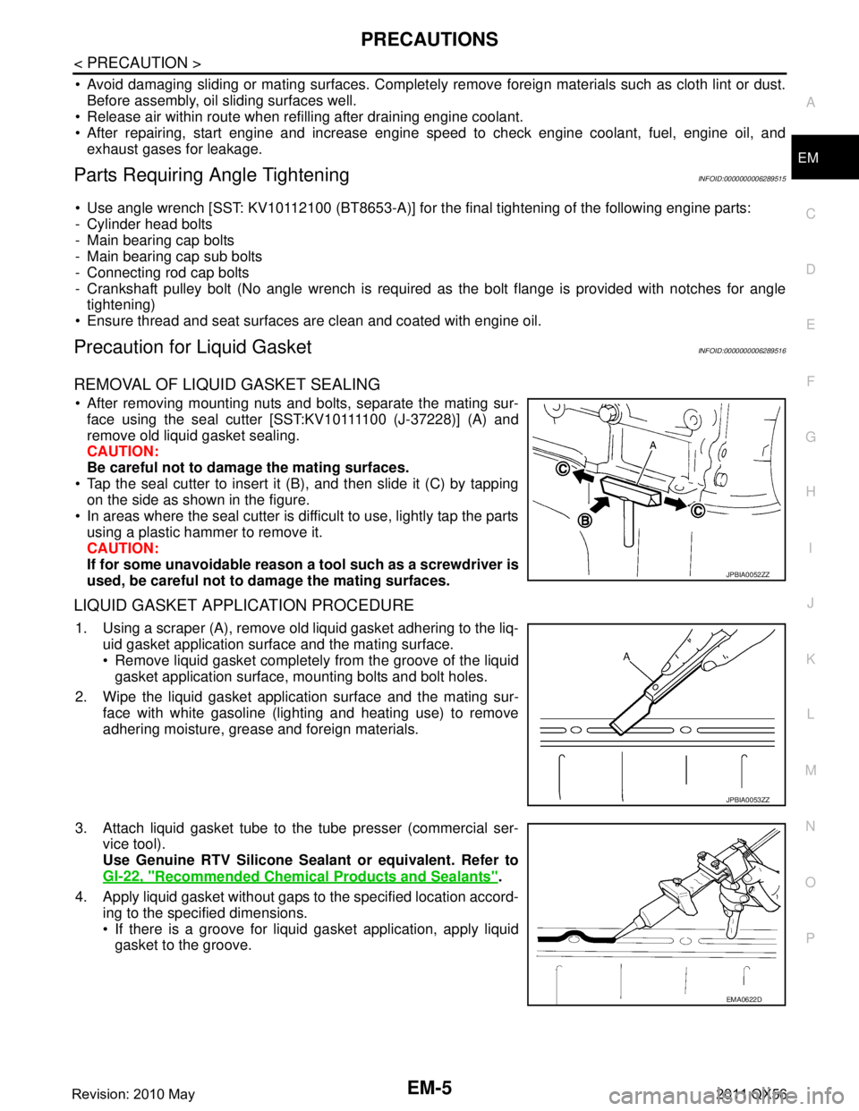
REMOVAL OF LIQUID GASKET SEALING
After removing mounting nuts and bolts, separate the mating sur- face using the seal cutter [SST:KV10111100 (J-37228)] (A) and
remove old liquid gasket sealing.
CAUTION:
Be careful not to damage the mating surfaces.
Tap the seal cutter to insert it (B), and then slide it (C) by tapping on the side as shown in the figure.
In areas where the seal cutter is difficult to use, lightly tap the parts using a plastic hammer to remove it.
CAUTION:
If for some unavoidable reason a tool such as a screwdriver is
used, be careful not to damage the mating surfaces.
LIQUID GASKET APPLICATION PROCEDURE
1. Using a scraper (A), remove old liquid gasket adhering to the liq- uid gasket application surface and the mating surface.
Remove liquid gasket completely from the groove of the liquidgasket application surface, mounting bolts and bolt holes.
2. Wipe the liquid gasket application surface and the mating sur- face with white gasoline (lighting and heating use) to remove
adhering moisture, grease and foreign materials.
3. Attach liquid gasket tube to the tube presser (commercial ser- vice tool).
Use Genuine RTV Silicone Seal ant or equivalent. Refer to
GI-22, "
Recommended Chemical Products and Sealants".
4. Apply liquid gasket without gaps to the specified location accord- ing to the specified dimensions.
If there is a groove for liquid gasket application, apply liquidgasket to the groove.
JPBIA0052ZZ
JPBIA0053ZZ
EMA0622D
Revision: 2010 May2011 QX56
Page 2572 of 5598
EM-10
< PREPARATION >
PREPARATION
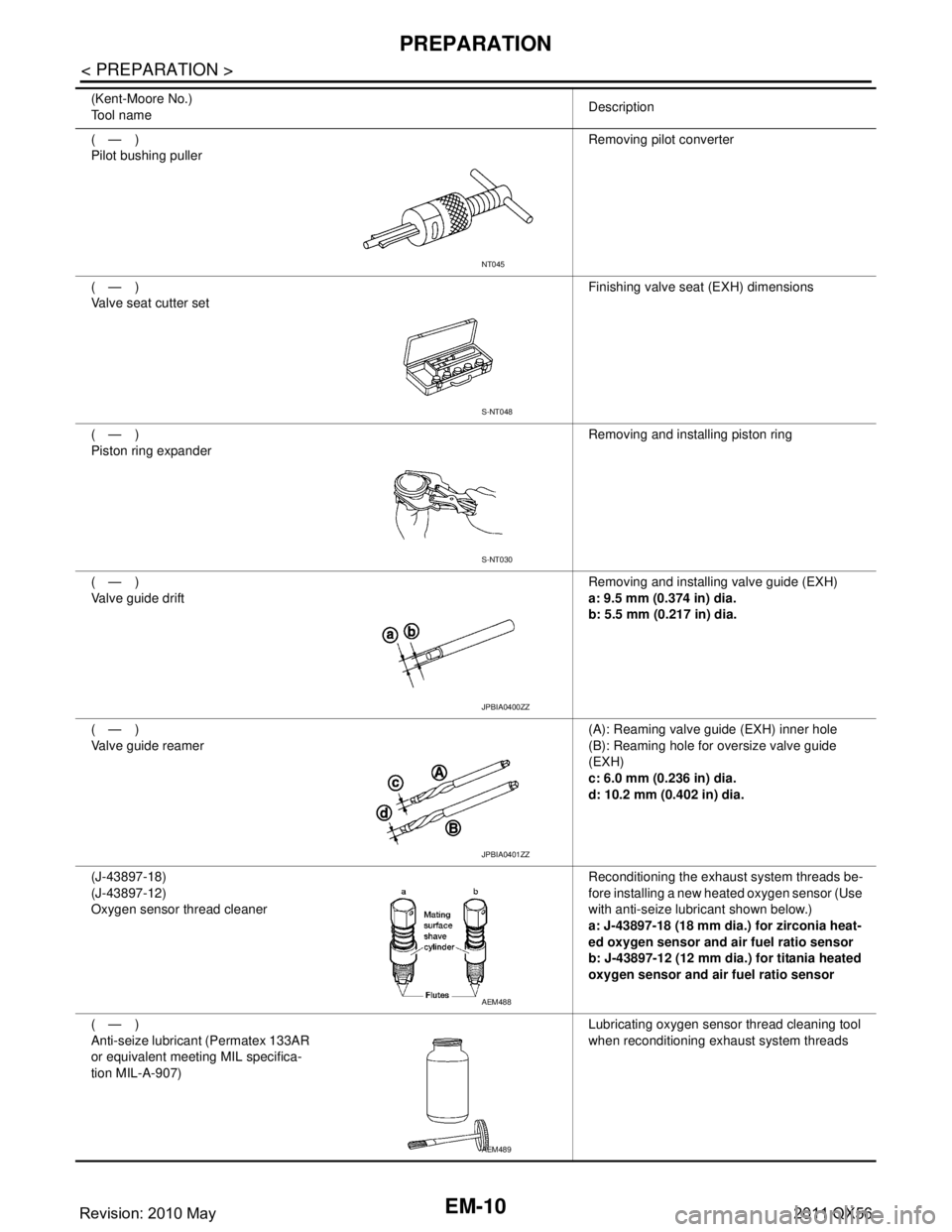
(—)
Pilot bushing pullerRemoving pilot converter
(—)
Valve seat cutter set Finishing valve seat (EXH) dimensions
(—)
Piston ring expander Removing and installing piston ring
(—)
Valve guide drift Removing and installing valve guide (EXH)
a: 9.5 mm (0.374 in) dia.
b: 5.5 mm (0.217 in) dia.
(—)
Valve guide reamer (A): Reaming valve guide (EXH) inner hole
(B): Reaming hole for oversize valve guide
(EXH)
c: 6.0 mm (0.236 in) dia.
d: 10.2 mm (0.402 in) dia.
(J-43897-18)
(J-43897-12)
Oxygen sensor thread cleaner Reconditioning the exhaust system threads be-
fore installing a new heated oxygen sensor (Use
with anti-seize lubricant shown below.)
a: J-43897-18 (18 mm dia.) for zirconia heat-
ed oxygen sensor and air fuel ratio sensor
b: J-43897-12 (12 mm dia.) for titania heated
oxygen sensor and air fuel ratio sensor
(—)
Anti-seize lubricant (Permatex 133AR
or equivalent meeting MIL specifica-
tion MIL-A-907) Lubricating oxygen sensor thread cleaning tool
when reconditioning exhaust system threads
(Kent-Moore No.)
Tool name
Description
NT045
S-NT048
S-NT030
JPBIA0400ZZ
JPBIA0401ZZ
AEM488
AEM489
Revision: 2010 May2011 QX56
Page 2652 of 5598
![INFINITI QX56 2011 Factory Service Manual
EM-90
< REMOVAL AND INSTALLATION >
CYLINDER HEAD
b. Drive out valve guide (EXH) with a press [under a 20 kN (2 ton,2.2 US ton, 2.0 lmp ton) pressure] or a hammer and the valve
guide drift (commercial INFINITI QX56 2011 Factory Service Manual
EM-90
< REMOVAL AND INSTALLATION >
CYLINDER HEAD
b. Drive out valve guide (EXH) with a press [under a 20 kN (2 ton,2.2 US ton, 2.0 lmp ton) pressure] or a hammer and the valve
guide drift (commercial](/img/42/57033/w960_57033-2651.png)
EM-90
< REMOVAL AND INSTALLATION >
CYLINDER HEAD
b. Drive out valve guide (EXH) with a press [under a 20 kN (2 ton,2.2 US ton, 2.0 lmp ton) pressure] or a hammer and the valve
guide drift (commercial service tool).
WARNING:
Cylinder head contains heat . When working, wear protec-
tive equipment to avo id getting burned.
ASSEMBLY
1. Install valve guide (EXH), if removed.
Replace with oversized [0.2 mm (0.008 in)] valve guide (EXH).
a. Using the valve guide reamer (commercial service tool) (A), ream cylinder head valve guide (EXH) hole.
b. Heat cylinder head to 110 to 130 °C (230 to 266 °F) by soaking in
heated oil (A).
c. Using the valve guide drift (commercial service tool), press valve guide (EXH) from camshaft side to the dimensions as shown in
the figure.
WARNING:
Cylinder head contains heat . When working, wear protec-
tive equipment to avo id getting burned.
SEM931C
Oversize (service) [0.2 mm (0.008 in)]:
: Refer to EM-135, "
CylinderHead".
JPBIA0185ZZ
JPBIA0184ZZ
Projection (A)
: Refer to EM-135, "
CylinderHead".
JPBIA0186ZZ
Revision: 2010 May2011 QX56
Page 2653 of 5598
CYLINDER HEADEM-91
< REMOVAL AND INSTALLATION >
C
DE
F
G H
I
J
K L
M A
EM
NP
O
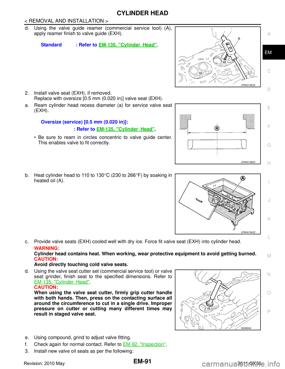
d. Using the valve guide reamer (commercial service tool) (A),
apply reamer finish to valve guide (EXH).
2. Install valve seat (EXH), if removed. Replace with oversize [0.5 mm (0.020 in)] valve seat (EXH).
a. Ream cylinder head recess diameter (a) for service valve seat (EXH).
Be sure to ream in circles concentric to valve guide center.
This enables valve to fit correctly.
b. Heat cylinder head to 110 to 130 °C (230 to 266 °F) by soaking in
heated oil (A).
c. Provide valve seats (EXH) cooled well with dry ice. Force fit valve seat (EXH) into cylinder head. WARNING:
Cylinder head contains heat. When working, w ear protective equipment to avoid getting burned.
CAUTION:
Avoid directly touching cold valve seats.
d. Using the valve seat cutter set (commercial service tool) or valve seat grinder, finish seat to the specified dimensions. Refer to
EM-135, "
CylinderHead".
CAUTION:
When using the valve seat cutt er, firmly grip cutter handle
with both hands. Then, press on the contacting surface all
around the circumference to cu t in a single drive. Improper
pressure on cutter or cutting many different times may
result in staged valve seat.
e. Using compound, grind to adjust valve fitting.
f. Check again for normal contact. Refer to EM-92, "
Inspection".
3. Install new valve oil seals as per the following: Standard : Refer to
EM-135, "
CylinderHead".
JPBIA0185ZZ
Oversize (service) [0.5 mm (0.020 in)]:
: Refer to EM-135, "
CylinderHead".
JPBIA0188ZZ
JPBIA0184ZZ
SEM934C
Revision: 2010 May2011 QX56