roof rack INFINITI QX56 2011 Factory Service Manual
[x] Cancel search | Manufacturer: INFINITI, Model Year: 2011, Model line: QX56, Model: INFINITI QX56 2011Pages: 5598, PDF Size: 94.53 MB
Page 368 of 5598

AV-220
< REMOVAL AND INSTALLATION >
ROOF SPEAKER
ROOF SPEAKER
Removal and InstallationINFOID:0000000006216386
REMOVAL
1. Remove roof garnish. Refer to INT-28, "Exploded View".
2. Remove roof speaker mounting screws from bracket.
3. Disconnect roof speaker connector to remove roof speaker.
INSTALLATION
Install in the reverse order of removal.
Revision: 2010 May2011 QX56
Page 679 of 5598

BRM-4
< PRECAUTION >
REPAIRING HIGH STRENGTH STEEL
PRECAUTION
REPAIRING HIGH STRENGTH STEEL
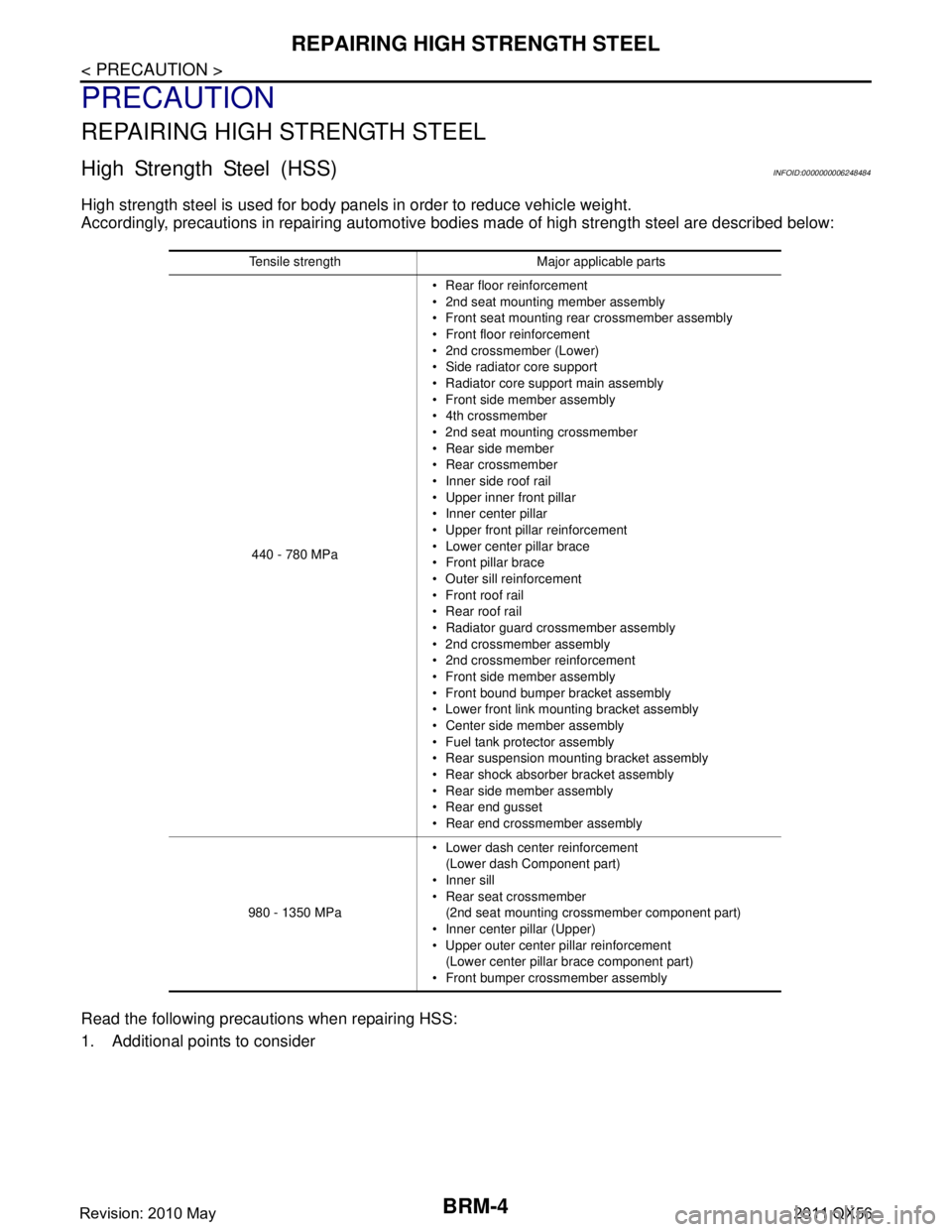
High Strength Steel (HSS)INFOID:0000000006248484
High strength steel is used for body panels in order to reduce vehicle weight.
Accordingly, precautions in repairing automotive bodies made of high strength steel are described below:
Read the following precautions when repairing HSS:
1. Additional points to consider
Tensile strength Major applicable parts 440 - 780 MPa Rear floor reinforcement
2nd seat mounting member assembly
Front seat mounting rear crossmember assembly
Front floor reinforcement
2nd crossmember (Lower)
Side radiator core support
Radiator core support main assembly
Front side member assembly
4th crossmember
2nd seat mounting crossmember
Rear side member
Rear crossmember
Inner side roof rail
Upper inner front pillar
Inner center pillar
Upper front pillar reinforcement
Lower center pillar brace
Front pillar brace
Outer sill reinforcement
Front roof rail
Rear roof rail
Radiator guard crossmember assembly
2nd crossmember assembly
2nd crossmember reinforcement
Front side member assembly
Front bound bumper bracket assembly
Lower front link mounting bracket assembly
Center side member assembly
Fuel tank protector assembly
Rear suspension mounting bracket assembly
Rear shock absorber bracket assembly
Rear side member assembly
Rear end gusset
Rear end crossmember assembly
980 - 1350 MPa Lower dash center reinforcement
(Lower dash Component part)
Inner sill
Rear seat crossmember
(2nd seat mounting crossmember component part)
Inner center pillar (Upper)
Upper outer center pillar reinforcement
(Lower center pillar brace component part)
Front bumper crossmember assembly
Revision: 2010 May2011 QX56
Page 687 of 5598

BRM-12
< PREPARATION >
BODY COMPONENT PARTS
NOTE:
For the parts without a number described in the figure, it is supplied only with the assembly part that the part is included with.
Tensile strength column shows the largest strength value of a part in the component part. No. Parts name
Tensile strength
(MPa) Both sided anti-corrosive
precoated steel sections
1. Hood Under 440×
2. Front fender (RH & LH) Under 440 ×
3. Inner side roof rail (RH & LH) 590 —
4. Upper inner front pillar (RH & LH) c. T=1.6 mm
(0.063 in)
980
caution—
5. Inner center pillar (RH & LH) d. T=1.6 mm
(0.063 in)
980
caution×
6. Center sill reinforcement assembly (RH & LH) Under 440 ×
7. Side body assembly (RH & LH) Refer to No.8 −13
8. Upper front pillar reinforcement (RH & LH) 590 —
9. Lower center pillar brace (RH & LH) e. T=1.8 mm
(0.071 in)
980
caution—
10. Front pillar brace (RH & LH) 590 —
11. Outer sill reinforcement (RH & LH) 590 ×
12. Outer front side body (RH & LH) Under 440 ×
13. Front fender bracket assembly (RH & LH) Under 440 ×
14. Outer sill (RH & LH) Under 440 ×
15. Front door assembly (RH & LH) 440 ×
16. Outer front door panel (RH & LH) Under 440 ×
17. Rear door assembly (RH & LH) 440 ×
18. Outer rear door panel (RH & LH) Under 440 ×
19. Back pillar reinforcement (RH & LH) Under 440 —
20. Inner back pillar (RH & LH) Under 440 —
21. Inner rear side roof rail (RH & LH) Under 440 —
22. Inner rear pillar (RH & LH) 590 —
23. Lower inner rear pillar (RH & LH)v Under 440 —
24. Side panel reinforcement (RH & LH) Under 440 —
25. Outer rear wheelhouse (RH & LH) Under 440 ×
26. Inner rear wheelhouse (RH & LH) Under 440 ×
27. Outer rear wheelhouse extension (RH & LH) Under 440 ×
28. Roof assembly Under 440 —
29. Front roof rail 440 —
30. Roof bow No.3 Under 440 —
31. Roof bow No.4 Under 440 —
32. Roof bow No.5 Under 440 —
33. Rear roof rail 440 —
34. Rear fender (RH & LH) Under 440 ×
35. Back pillar assembly (RH & LH) Under 440 —
36. Rear fender bracket (RH & LH) Under 440 —
37. Fuel filler lid Under 440 ×
38. Rear fender extension (RH & LH) Under 440 ×
39. Back door Under 440 ×
Revision: 2010 May2011 QX56
Page 698 of 5598

BODY CONSTRUCTIONBRM-23
< REMOVAL AND INSTALLATION >
C
DE
F
G H
I
J
L
M A
B
BRM
N
O P
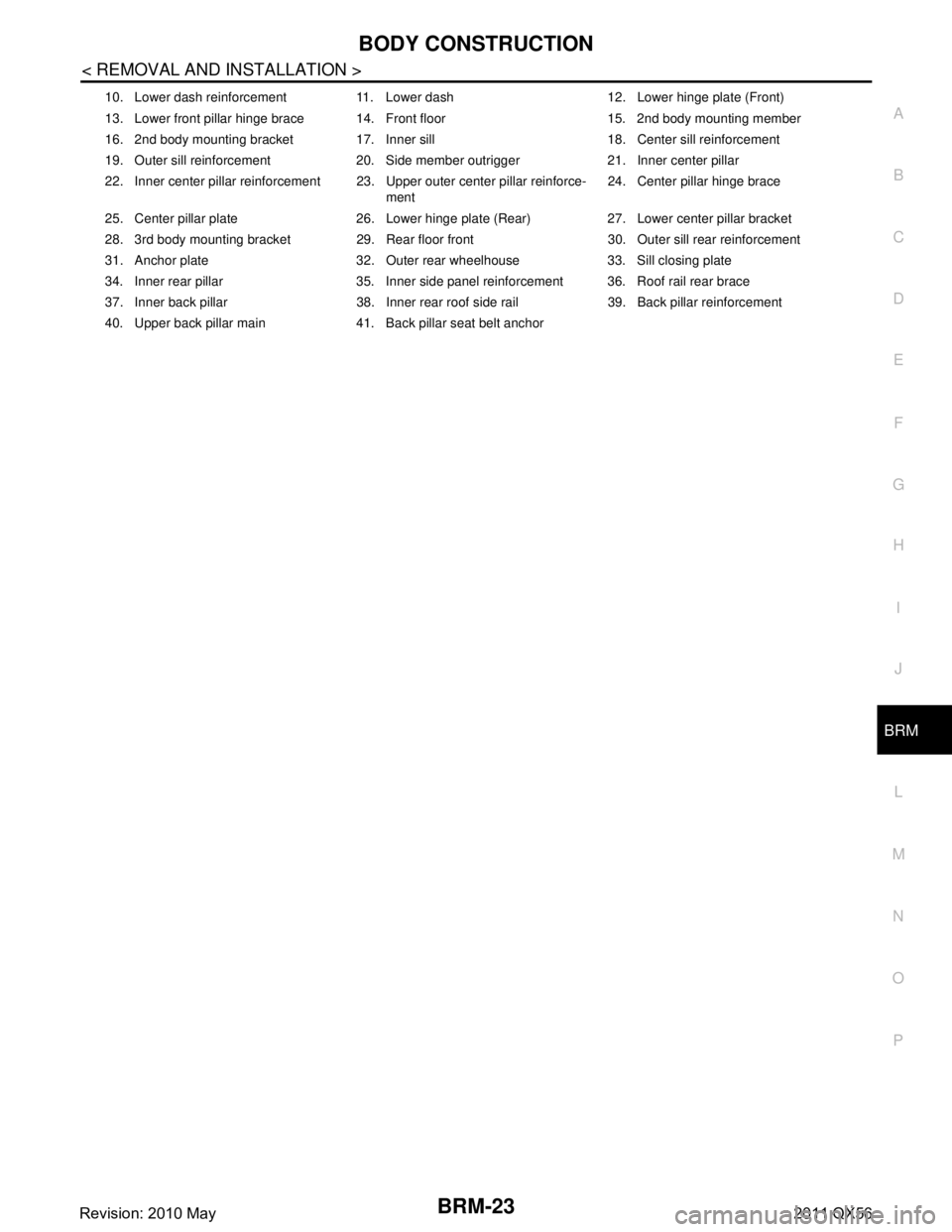
10. Lower dash reinforcement 11. Lower dash 12. Lower hinge plate (Front)
13. Lower front pillar hinge brace 14. Front floor 15. 2nd body mounting member
16. 2nd body mounting bracket 17. Inner sill 18. Center sill reinforcement
19. Outer sill reinforcement 20. Side member outrigger 21. Inner center pillar
22. Inner center pillar reinforcement 23. Upper outer center pillar reinforce- ment24. Center pillar hinge brace
25. Center pillar plate 26. Lower hinge plate (Rear) 27. Lower center pillar bracket
28. 3rd body mounting bracket 29. Rear floor front 30. Outer sill rear reinforcement
31. Anchor plate 32. Outer rear wheelhouse 33. Sill closing plate
34. Inner rear pillar 35. Inner side panel reinforcement 36. Roof rail rear brace
37. Inner back pillar 38. Inner rear roof side rail 39. Back pillar reinforcement
40. Upper back pillar main 41. Back pillar seat belt anchor
Revision: 2010 May2011 QX56
Page 723 of 5598

BRM-48
< SERVICE DATA AND SPECIFICATIONS (SDS)
BODY ALIGNMENT
SERVICE DATA AND SPECIFICATIONS (SDS)
BODY ALIGNMENT
Body Center MarksINFOID:0000000006248507
A mark is placed on each part of the body to indicate the vehicle center. When repairing the vehicle frame
(members, pillars, etc.) damaged by an accident which it enables more accurate and effective repair by using
these marks together with body alignment specifications.
Unit: mm (in)
DescriptionINFOID:0000000006248508
All dimensions indicated in the figures are actual.
When using a tracking gauge, adjust both pointers to equal length. Then check the pointers and gauge itself
to make sure there is no free play.
: Vehicle front
Points Portion Marks
A Upper dash Hole 7 ×12 (0.28 ×0.47)
B Cowl top Embossment
C Rear roof Indent
JSKIA1895ZZ
Revision: 2010 May2011 QX56
Page 731 of 5598

BRM-56
< SERVICE DATA AND SPECIFICATIONS (SDS)
BODY ALIGNMENT
Unit: mm (in)
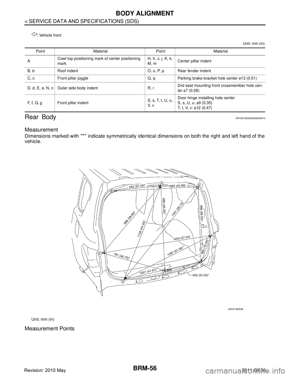
Rear BodyINFOID:0000000006248512
Measurement
Dimensions marked with ″*″ indicate symmetrically identical dimensions on both the right and left hand of the
vehicle.
Measurement Points
: Vehicle front
Point Material Point Material
A Cowl top positioning mark of center positioning
mark H, h, J, j, K, k,
M, m
Center pillar indent
B, b Roof indent O, o, P, p Rear fender indent
C, c Front pillar joggle Q, q Parking brake bracket hole center φ13 (0.51)
D, d, E, e, N, n Outer side body indent R, r 2nd seat mounting front crossmember hole cen-
ter
φ7 (0.28)
F, f, G, g Front pillar indent S, s, T, t, U, u,
V, vDoor hinge installing hole center
S, s, U, u:
φ9 (0.35)
T, t, V, v: φ12 (0.47)
Unit: mm (in)
JSKIA1902GB
Revision: 2010 May2011 QX56
Page 1748 of 5598

DLK-212
< SYMPTOM DIAGNOSIS >
SQUEAK AND RATTLE TROUBLE DIAGNOSES
Most of these incidents can be repaired by adjusting, securing or insulating the item(s) or component(s) caus-
ing the noise.
SUNROOF/HEADLINING
Noises in the sunroof/headlining area c an often be traced to one of the following:
1. Sunroof lid, rail, linkage or seals making a rattle or light knocking noise
2. Sunvisor shaft shaking in the holder
3. Front or rear windshield touching headlining and squeaking
Again, pressing on the components to stop the noise while duplicating the conditions can isolate most of these
incidents. Repairs usually consist of insulating with felt cloth tape.
SEATS
When isolating seat noise it is important to note t he position the seat is in and the load placed on the seat
when the noise is present. These conditions should be duplicated when verifying and isolating the cause of
the noise.
Cause of seat noise include:
1. Headrest rods and holder
2. A squeak between the seat pad cushion and frame
3. Rear seatback lock and bracket
These noises can be isolated by moving or pressing on the suspected components while duplicating the con-
ditions under which the noise occurs. Most of thes e incidents can be repaired by repositioning the component
or applying urethane tape to the contact area.
UNDERHOOD
Some interior noise may be caused by components under the hood or on the engine wall. The noise is then
transmitted into the passenger compartment.
Causes of transmitted underhood noise include:
1. Any component mounted to the engine wall
2. Components that pass through the engine wall
3. Engine wall mounts and connectors
4. Loose radiator mounting pins
5. Hood bumpers out of adjustment
6. Hood striker out of adjustment
These noises can be difficult to isolate since they cannot be reached from the interior of the vehicle. The best
method is to secure, move or insulate one component at a time and test drive the \
vehicle. Also, engine RPM
or load can be changed to isolate the noise. Repairs can usually be made by moving, adjusting, securing, or
insulating the component causing the noise.
Revision: 2010 May2011 QX56
Page 1768 of 5598

DLK-232
< REMOVAL AND INSTALLATION >
BACK DOOR
BACK DOOR
Exploded ViewINFOID:0000000006226086
BACK DOOR ASSEMBLY
BACK DOOR ASSEMBLY : Removal and InstallationINFOID:0000000006226087
CAUTION:
Operate with two workers, because of its heavy weight.
Use protective tape or cloth to protect fr om damage during remove and installation.
REMOVAL
1. Remove stud ball of back door support rod. Refer to DLK-247, "BACK DOOR SUPPORT ROD : Removal
and Installation".
2. Remove roof garnish. Refer to INT-29, "
Removal and Installation".
1. Back door hinge 2. TORX bolt 3. Back door striker
4. Back door weather-strip 5. Stopper seal 6. Back door stay bracket
7. Back door stay 8. Back door lower bracket 9. Bumper rubber (side)
10. Bumper rubber bracket 11. Drain plug 12. Bumper rubber (lower)
13. Back door assembly
A : Center mark
B: Seam
Refer to GI-4, "
Components" for symbols in the figure.
JMKIA5482GB
Revision: 2010 May2011 QX56
Page 2864 of 5598

SQUEAK AND RATTLE TROUBLE DIAGNOSESEXT-9
< SYMPTOM DIAGNOSIS >
C
DE
F
G H
I
J
L
M A
B
EXT
N
O P
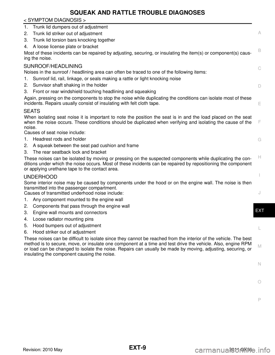
1. Trunk lid dumpers out of adjustment
2. Trunk lid striker out of adjustment
3. Trunk lid torsion bars knocking together
4. A loose license plate or bracket
Most of these incidents can be repaired by adjusting, se curing, or insulating the item(s) or component(s) caus-
ing the noise.
SUNROOF/HEADLINING
Noises in the sunroof / headlining area can of ten be traced to one of the following items:
1. Sunroof lid, rail, linkage, or seals making a rattle or light knocking noise
2. Sunvisor shaft shaking in the holder
3. Front or rear windshield touching headlining and squeaking
Again, pressing on the components to stop the noise while duplicating the conditions can isolate most of these
incidents. Repairs usually consist of insulating with felt cloth tape.
SEATS
When isolating seat noise it is important to note the position the seat is in and the load placed on the seat
when the noise occurs. These conditions should be duplic ated when verifying and isolating the cause of the
noise.
Causes of seat noise include:
1. Headrest rods and holder
2. A squeak between the seat pad cushion and frame
3. The rear seatback lock and bracket
These noises can be isolated by moving or pressing on the suspected components while duplicating the con-
ditions under which the noise occurs. Most of thes e incidents can be repaired by repositioning the component
or applying urethane tape to the contact area.
UNDERHOOD
Some interior noise may be caused by components under the hood or on the engine wall. The noise is then
transmitted into the passenger compartment.
Causes of transmitted underhood noise include:
1. Any component mounted to the engine wall
2. Components that pass through the engine wall
3. Engine wall mounts and connectors
4. Loose radiator mounting pins
5. Hood bumpers out of adjustment
6. Hood striker out of adjustment
These noises can be difficult to isolate since they cannot be reached from the interior of the vehicle. The best
method is to secure, move, or insulate one component at a time and test drive the vehicle. Also, engine RPM
or load can be changed to isolate the noise. Repairs c an usually be made by moving, adjusting, securing, or
insulating the component causing the noise.
Revision: 2010 May2011 QX56
Page 3037 of 5598

GW-8
< SYMPTOM DIAGNOSIS >
SQUEAK AND RATTLE TROUBLE DIAGNOSES
3. The trunk lid torsion bars knocking together
4. A loose license plate or bracket
Most of these incidents can be repaired by adjusting, securing or insulatingthe item(s) or component(s) caus-
ing the noise.
SUNROOF/HEADLINING
Noises in the sunroof/headlining area c an often be traced to one of the following:
1. Sunroof lid, rail, linkage or seals making a rattle or light knockingnoise
2. Sunvisor shaft shaking in the holder
3. Front or rear windshield touching headlining and squeaking
Again, pressing on the components to stop the noise while duplicatingthe conditions can isolate most of these
incidents. Repairs usually consistof insulating with felt cloth tape.
SEATS
When isolating seat noise it's important to note the pos ition the seatis in and the load placed on the seat when
the noise is present. These conditionsshould be duplic ated when verifying and isolating the cause of the
noise.
Cause of seat noise include:
1. Headrest rods and holder
2. A squeak between the seat pad cushion and frame
3. The rear seatback lock and bracket
These noises can be isolated by moving or pressing on the suspectedcomponents while duplicating the condi-
tions under which the noise occurs. Most of these incidents can be repaired by repositioning the component
orapplying urethane tape to the contact area.
UNDERHOOD
Some interior noise may be caused by components under the hood or onthe engine wall. The noise is then
transmitted into the passenger compartment.
Causes of transmitted underhood noise include:
1. Any component mounted to the engine wall
2. Components that pass through the engine wall
3. Engine wall mounts and connectors
4. Loose radiator mounting pins
5. Hood bumpers out of adjustment
6. Hood striker out of adjustment
These noises can be difficult to isolate since they cannot be reached from the interior of the vehicle. The best
method is to secure, move or insulate one component at a time and test drive the \
vehicle. Also, engine RPM
or load can be changed to isolate the noise. Repairs can usually be made by moving, adjusting, securing, or
insulating the component causing the noise.
Revision: 2010 May2011 QX56