shift position indicator INFINITI QX56 2011 Factory Service Manual
[x] Cancel search | Manufacturer: INFINITI, Model Year: 2011, Model line: QX56, Model: INFINITI QX56 2011Pages: 5598, PDF Size: 94.53 MB
Page 17 of 5598

ADP-8
< SYSTEM DESCRIPTION >
COMPONENT PARTS
ABS actuator and electric unit (control unit)Transmit the vehicle speed signal to driver seat control unit via
CAN communication.
A/T sift selector (Detention switch) Detention switch is installed on A/T shift selector. It is turned
OFF when A/T shift selector is in P position.
Driver seat control unit judges that A/T shift selector is in P posi- tion if continuity does not exist in this circuit.
Door mirror remote con-
trol switch Mirror switch
Mirror switch is integrated in
door mirror remote control switch.
It operates angle of door mirror face.
It transmits mirror face adjust operation to automatic drive posi- tioner control unit.
Changeover switch Changeover switch is integrated
in door mirror remote control
switch.
Changeover switch has three positions (L, N and R).
It changes operating door mirror motor by transmitting control signal to automatic drive positioner control unit.
Open/close switch Open/close switch is integrated in door mirror remote control
switch.
Power is supplied to folding mi rror from door mirror remote con-
trol switch when operating switch.
Tilt & telescopic switch Tilt switch
Tilt switch is equipped to steering column.
The operation signal is input to automatic drive positioner control
unit when tilt switch is operated.
Telescopic switch Telescopic switch is equipped to steering column.
The operation signal is input to automatic drive positioner control
unit when telescopic switch is operated.
Seat memory switch Set switch
It is used for registration and setting change of driving position and
Intelligent Key interlock function.
Seat memory switch The maximum 2 driving positions can be registered by memory
switch 1 to 2.
Driving position is set to the registered driving position when memory switch is pressed while operation conditions are satis-
fied.
Seat memory indicator Memory indicator indicates the status of auto driving position sys-
tem by turning ON or blinking.
Power seat switch Sliding switch
Sliding switch is equipped to power seat switch on seat cushion
side surface.
The operation signal is input to driver seat control unit when slid- ing switch is operated.
Reclining switch The operation signal is input to driver seat control unit when re-
clining switch is operated.
The operation signal is input to driver seat control unit when re-
clining switch is operated.
Lifting switch (front) Lifting switch (front) is equipped to power seat switch on seat
cushion side surface.
The operation signal is input to driver seat control unit when lift-
ing switch (front) is operated.
Lifting switch (rear) Lifting switch (rear) is equipped to power seat switch on seat
cushion side surface.
The operation signal is input to driver seat control unit when lift-
ing switch (rear) is operated.
Component parts Description
Revision: 2010 May2011 QX56
Page 25 of 5598

ADP-16
< SYSTEM DESCRIPTION >
SYSTEM
3. Push desired memory switch.
4. Driver seat, steering and door mirror will move to the memorized position.
OPERATION CONDITION
Satisfy all of the following items. The memory function is not performed if these items are not satisfied.
* : When timer function does not operate.
DETAIL FLOW
TIMER FUNCTION
The memory function can be performed for 45 seconds after opening the driver door even if the ignition
switch position is in OFF position.
Satisfy all of the following items. The timer functi on is not performed if these items are not satisfied.
Item Request status
Ignition position ON
*
Switch inputs
Power seat switch
Tilt & telescopic switch
Door mirror control switch
Set switch
Memory switchOFF
(Not operated)
A/T shift selector P position
Memory function Registered
Vehicle speed 0 Km/h (0 MPH)
CONSULT-III Not connected
Order Input Output Control unit condition
1 Memory switch — The memory switch signal is inputted to the driver seat control unit
when memory switch 1 or 2 is operated.
2— Motors
(Seat, Steering,
door mirror)Driver seat control unit operates each motor of seat when it recogniz-
es the memory switch pressed for 0.5 second or more and requests
each motor operation to automatic drive positioner control unit via
UART communication. The automatic drive positioner control unit op-
erates each motor.
Memory switch Indica-
tor Driver seat control unit requests the flashing of memory indicator
while either of the motors is operating. The driver seat control unit il-
luminates the memory indicator.
3 Sensors
(Seat, steering col-
umn, door mirror) —Driver seat control unit judges the operating seat position with each
seat sensor input. The positions of the steering column and outside
mirror are monitored with each sensor signal. Driver seat control unit
stops the operation of each motor when each part reaches the record-
ed address.
4— Memory switch Indica-
torDriver seat control unit requests the illumination of memory indicator
after all motors stop. The driver seat control unit illuminates the mem-
ory indicator for 5 seconds.
Item Request status
Ignition position OFF
Set switch/memory switch OFF
Memory function Registered
A/T shift selector P position
Steering lock unit status LOCK
Driver side door switch OFF
CUNSULT-III Not connected
Revision: 2010 May2011 QX56
Page 62 of 5598
INSPECTION AND ADJUSTMENTADP-53
< BASIC INSPECTION >
C
DE
F
G H
I
K L
M A
B
ADP
N
O P
>> END
4. STEP B-1
Drive the vehicle at more than 25 km/h (16 MPH).
>> END
MEMORY STORING
MEMORY STORING : DescriptionINFOID:0000000006248330
Always perform the memory storage when the battery terminal is disconnected or the driver seat control unit is
replaced. The memory function will not operate normally if no memory storage is performed.
MEMORY STORING : Special Repair RequirementINFOID:0000000006248331
Memory Storage Procedure
Two positions for the driver seat, steering column and outside mirror can be stored for memory operation by
following procedure.
1.STEP 1
Check the following conditions.
Ignirion switch: ON
A/T shift selector: P position
>> GO TO 2.
2.STEP 2
Adjust driver seat, steering colu mn and outside mirror position manually.
>> GO TO 3.
3.STEP 3
1. Push set switch. NOTE:
Memory indicator for which driver seat position is already retained in memory is illuminated for 5 sec-
onds.
Memory indicator for which driver seat position is not retained in memory is illuminated for 0.5 second.
2. Push the memory switch (1 or 2) for at least 1 second within 5 seconds after pushing the set switch.
NOTE:
To enter driver seat positions into blank memo ry, memory indicator will be turned on for 5 seconds.
To modify driver seat positions, memory indicato r will be turned OFF for 0.5 second, then turned ON for
5 seconds.
NOTE:
If memory is stored in the same memory switch, the previous memory will be deleted.
>> GO TO 4.
4.STEP 4
Confirm the operation of each part with memory operation.
>> END
INTELLIGENT KEY IN TERLOCK STORING
Revision: 2010 May2011 QX56
Page 168 of 5598
AV-20
< SYSTEM DESCRIPTION >
SYSTEM
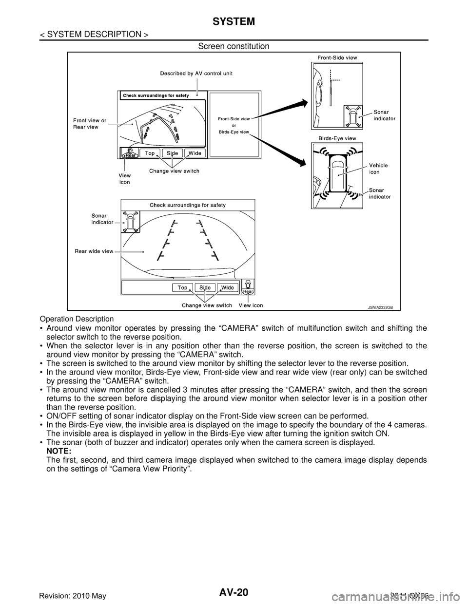
Screen constitution
Operation Description
Around view monitor operates by pressing the “CAMERA” switch of multifunction switch and shifting the
selector switch to the reverse position.
When the selector lever is in any position other t han the reverse position, the screen is switched to the
around view monitor by pressing the “CAMERA” switch.
The screen is switched to the around view monitor by sh ifting the selector lever to the reverse position.
In the around view monitor, Birds-Eye view, Front-si de view and rear wide view (rear only) can be switched
by pressing the “CAMERA” switch.
The around view monitor is cancelled 3 minutes af ter pressing the “CAMERA” switch, and then the screen
returns to the screen before displaying the around view monitor when selector lever is in a position other
than the reverse position.
ON/OFF setting of sonar indicator display on the Front-Side view screen can be performed.
In the Birds-Eye view, the invisible area is displa yed on the image to specify the boundary of the 4 cameras.
The invisible area is displayed in yellow in the Birds-Eye view after turning the ignition switch ON.
The sonar (both of buzzer and indicator) operates only when the camera screen is displayed. NOTE:
The first, second, and third camera image displayed when switched to the camera image display depends
on the settings of “Camera View Priority”.
JSNIA2332GB
Revision: 2010 May2011 QX56
Page 329 of 5598

AV
FRONT CAMERA COMMUNICATION SIGNAL CIRCUITAV-181
< DTC/CIRCUIT DIAGNOSIS >
C
DE
F
G H
I
J
K L
M B A
O P
FRONT CAMERA COMMUNICATION SIGNAL CIRCUIT
DescriptionINFOID:0000000006216350
Around view monitor control unit supplies to the front camera, rear camera and side camera. And then it
superimpose the images from each camera and outputs then to the front display unit.
Superimpose the guiding lines, predictive course line and sonar indicator to the camera image that outputs
to the front display unit.
Around view monitor control unit performs the rec eption/transmission of communication signal with each
camera.
Diagnosis ProcedureINFOID:0000000006216351
1.CHECK CONTINUITY COMMUNI CATION SIGNAL CIRCUIT
1. Turn ignition switch OFF.
2. Disconnect around view monitor control unit connector and front camera connector.
3. Check continuity between around view monitor c ontrol unit harness connector and front camera harness
connector.
4. Check continuity between around view monitor control unit harness connector and ground.
Is inspection result normal?
YES >> GO TO 2.
NO >> Repair harness or connector.
2.CHECK COMMUNICATION SIGNAL
1. Connect around view monitor control uni t connector and front camera connector.
2. Turn ignition switch ON.
3. Check signal between around view monitor control unit harness connector and ground.
Is inspection result normal?
YES >> Replace around view monitor control unit. Refer to AV-233, "Removal and Installation".
NO >> Replace front camera. Refer to AV-234, "
Removal and Installation".
Around view monitor control
unit Front camera
Continuity
Connector Terminal Connector Terminal
M49 45 E50 6 Existed
Around view monitor control unit GroundContinuity
Connector Terminal
B49 45 Not existed
(+)
(− ) Condition Reference value
Around view monitor control
unit
Connector Terminal
M49 45 Ground “CAMERA” switch is ON or shift
position is “R”.
JSNIA0836GB
Revision: 2010 May2011 QX56
Page 330 of 5598

AV-182
< DTC/CIRCUIT DIAGNOSIS >
FRONT CAMERA IMAGE SIGNAL CIRCUIT
FRONT CAMERA IMAGE SIGNAL CIRCUIT
DescriptionINFOID:0000000006216352
Around view monitor control unit supplies to the front camera, rear camera and side came\
ra. And then itsuperimpose the images from each camera and outputs then to the front display unit.
Superimpose the guiding lines, predictive course line and sonar indicator to the camera image that outputs
to the front display unit.
Around view monitor control unit performs the rec eption/transmission of communication signal with each
camera.
Diagnosis ProcedureINFOID:0000000006216353
1.CHECK CONTINUITY FRONT CAMERA POWER SUPPLY AND GROUND CIRCUIT
1. Turn ignition switch OFF.
2. Disconnect around view monitor control unit connector and front camera connector.
3. Check continuity between around view monitor c ontrol unit harness connector and front camera harness
connector.
4. Check continuity between around view m onitor control unit harness connector and ground.
Is inspection result normal?
YES >> GO TO 2.
NO >> Repair harness or connector.
2.CHECK VOLTAGE FRONT CAMERA POWER SUPPLY
1. Connect around view monitor control unit connector and front camera connector.
2. Turn ignition switch ON.
3. Check voltage between around view m onitor control unit harness connector.
Is inspection result normal?
YES >> GO TO 3.
NO >> Replace around view monitor control unit. Refer to AV-233, "
Removal and Installation".
3.CHECK CONTINUITY FRONT CAMERA IMAGE SIGNAL CIRCUIT
1. Turn ignition switch OFF.
2. Disconnect around view monitor control unit connector and front camera connector.
3. Check continuity between around view monitor c ontrol unit harness connector and front camera harness
connector.
Around view monitor control
unit Front camera
Continuity
Connector Terminals Connector Terminals
M49 44
E50 2
Existed
46 1
Around view monitor control unit GroundContinuity
Connector Terminal
M49 46 Not existed
(+)
(− ) Condition Vo l ta g e
(Approx.)
Around view monitor control
unit
Connector Terminal
M49 46 Ground “CAMERA” switch is ON or
shift position is “R”.
6.0 V
Revision: 2010 May2011 QX56
Page 332 of 5598

AV-184
< DTC/CIRCUIT DIAGNOSIS >
REAR CAMERA COMMUNICATION SIGNAL CIRCUIT
REAR CAMERA COMMUNICATION SIGNAL CIRCUIT
DescriptionINFOID:0000000006216354
Around view monitor control unit supplies to the front camera, rear camera and side came\
ra. And then it
superimpose the images from each camera and outputs then to the front display unit.
Superimpose the guiding lines, predictive course line and sonar indicator to the camera image that outputs
to the front display unit.
Around view monitor control unit performs the rec eption/transmission of communication signal with each
camera.
Diagnosis ProcedureINFOID:0000000006216355
1.CHECK CONTINUITY COMMUNI CATION SIGNAL CIRCUIT
1. Turn ignition switch OFF.
2. Disconnect around view monitor control un it connector and rear camera connector.
3. Check continuity between around view monitor control unit harness connector and rear camera harness connector.
4. Check continuity between around view m onitor control unit harness connector and ground.
Is inspection result normal?
YES >> GO TO 2.
NO >> Repair harness or connector.
2.CHECK COMMUNICATION SIGNAL
1. Connect around view monitor control unit connector and rear camera connector.
2. Turn ignition switch ON.
3. Check signal between around view monitor control unit harness connector and ground.
Is inspection result normal?
YES >> Replace around view monitor control unit. Refer to AV-233, "Removal and Installation".
NO >> Replace rear camera. Refer to AV-235, "
Removal and Installation".
Around view monitor control
unit Rear camera
Continuity
Connector Terminal Connector Terminal
M48 35 D164 4 Existed
Around view monitor control unit GroundContinuity
Connector Terminal
M48 35 Not existed
(+)
(− ) Condition Reference value
Around view monitor control
unit
Connector Terminal
M48 35 Ground “CAMERA” switch is ON or shift
position is “R”.
JSNIA0836GB
Revision: 2010 May2011 QX56
Page 333 of 5598

AV
REAR CAMERA IMAGE SIGNAL CIRCUITAV-185
< DTC/CIRCUIT DIAGNOSIS >
C
DE
F
G H
I
J
K L
M B A
O P
REAR CAMERA IMAGE SIGNAL CIRCUIT
DescriptionINFOID:0000000006216356
Around view monitor control unit supplies to the front camera, rear camera and side camera. And then it
superimpose the images from each camera and outputs then to the front display unit.
Superimpose the guiding lines, predictive course line and sonar indicator to the camera image that outputs
to the front display unit.
Around view monitor control unit performs the rec eption/transmission of communication signal with each
camera.
Diagnosis ProcedureINFOID:0000000006216357
1.CHECK CONTINUITY REAR CAMERA POWER SUPPLY AND GROUND CIRCUIT
1. Turn ignition switch OFF.
2. Disconnect around view monitor control unit connector and rear camera connector.
3. Check continuity between around view monitor c ontrol unit harness connector and rear camera harness
connector.
4. Check continuity between around view monitor control unit harness connector and ground.
Is inspection result normal?
YES >> GO TO 2.
NO >> Repair harness or connector.
2.CHECK VOLTAGE REAR CAMERA POWER SUPPLY
1. Connect around view monitor control unit connector and rear camera connector.
2. Turn ignition switch ON.
3. Check voltage between around view monitor control unit harness connector and ground.
Is inspection result normal?
YES >> GO TO 3.
NO >> Replace around view monitor control unit. Refer to AV-233, "
Removal and Installation".
3.CHECK CONTINUITY REAR CAMERA IMAGE SIGNAL CIRCUIT
1. Turn ignition switch OFF.
2. Disconnect around view monitor control unit connector and rear camera connector.
3. Check continuity between around view monitor c ontrol unit harness connector and rear camera harness
connector.
Around view monitor control
unit Rear camera
Continuity
Connector Terminals Connector Terminals
M48 36
D164 8
Existed
38 7
Around view monitor control unit GroundContinuity
Connector Terminal
M48 36 Not existed
(+)
(− ) Condition Vo l ta g e
(Approx.)
Around view monitor control
unit
Connector Terminal
M48 36 Ground “CAMERA” switch is ON or
shift position is “R”.
6.0 V
Revision: 2010 May2011 QX56
Page 335 of 5598

AV
SIDE CAMERA LH COMMUNICATION SIGNAL CIRCUIT
AV-187
< DTC/CIRCUIT DIAGNOSIS >
C
D E
F
G H
I
J
K L
M B A
O P
SIDE CAMERA LH COMMUNI CATION SIGNAL CIRCUIT
DescriptionINFOID:0000000006216358
Around view monitor control unit supplies to the front camera, rear camera and side camera. And then it
superimpose the images from each camera and outputs then to the front display unit.
Superimpose the guiding lines, predictive course line and sonar indicator to the camera image that outputs
to the front display unit.
Around view monitor control unit performs the rec eption/transmission of communication signal with each
camera.
Diagnosis ProcedureINFOID:0000000006216359
1.CHECK CONTINUITY COMMUNI CATION SIGNAL CIRCUIT
1. Turn ignition switch OFF.
2. Disconnect around view monitor control unit connector and door mirror (driver side) connector.
3. Check continuity between around view monitor control unit harness connector and door mirror (driver side) harness connector.
4. Check continuity between around view monitor control unit harness connector and ground.
Is inspection result normal?
YES >> GO TO 2.
NO >> Repair harness or connector.
2.CHECK COMMUNICATION SIGNAL
1. Connect around view monitor control unit c onnector and door mirror (driver side) connector.
2. Turn ignition switch ON.
3. Check signal between around view monitor control unit harness connector and ground.
Is inspection result normal?
YES >> Replace around view monitor control unit. Refer to AV-233, "Removal and Installation".
NO >> Replace side camera LH. Refer to AV-236, "
Removal and Installation".
Around view monitor control
unit Door mirror
(driver side) Continuity
Connector Terminal Connector Terminal
M49 47 D3 3 Existed
Around view monitor control unit GroundContinuity
Connector Terminal
M49 47 Not existed
(+)
(− ) Condition Reference value
Around view monitor control
unit
Connector Terminal
M49 47 Ground “CAMERA” switch is ON or shift
position is “R”.
JSNIA0836GB
Revision: 2010 May2011 QX56
Page 336 of 5598

AV-188
< DTC/CIRCUIT DIAGNOSIS >
SIDE CAMERA LH IMAGE SIGNAL CIRCUIT
SIDE CAMERA LH IMAGE SIGNAL CIRCUIT
DescriptionINFOID:0000000006216360
Around view monitor control unit supplies to the front camera, rear camera and side came\
ra. And then itsuperimpose the images from each camera and outputs then to the front display unit.
Superimpose the guiding lines, predictive course line and sonar indicator to the camera image that outputs
to the front display unit.
Around view monitor control unit performs the rec eption/transmission of communication signal with each
camera.
Diagnosis ProcedureINFOID:0000000006216361
1.CHECK CONTINUITY SIDE CAMERA LH POWER SUPPLY AND GROUND CIRCUIT
1. Turn ignition switch OFF.
2. Disconnect around view monitor control unit connector and door mirror (driver side) connector.
3. Check continuity between around view monitor c ontrol unit harness connector and door mirror (driver
side) harness connector.
4. Check continuity between around view m onitor control unit harness connector and ground.
Is inspection result normal?
YES >> GO TO 2.
NO >> Repair harness or connector.
2.CHECK VOLTAGE SIDE CA MERA LH POWER SUPPLY
1. Connect around view monitor control unit connector and door mirror (driver side) connector.
2. Turn ignition switch ON.
3. Check voltage between around view monito r control unit harness connector and ground.
Is inspection result normal?
YES >> GO TO 3.
NO >> Replace around view monitor control unit. Refer to AV-233, "
Removal and Installation".
3.CHECK CONTINUITY SIDE CAMERA LH IMAGE SIGNAL CIRCUIT
1. Turn ignition switch OFF.
2. Disconnect around view monitor control unit connector and door mirror (driver side) connector.
3. Check continuity between around view monitor c ontrol unit harness connector and door mirror (driver
side) harness connector.
Around view monitor control
unit Door mirror (driver side)
Continuity
Connector Terminals Connector Terminals
M49 48
D3 6
Existed
50 18
Around view monitor control unit GroundContinuity
Connector Terminal
M49 48 Not existed
(+)
(− ) Condition Vo l ta g e
(Approx.)
Around view monitor control
unit
Connector Terminal
M49 48 Ground “CAMERA” switch is ON or
shift position is “R”.
6.0 V
Revision: 2010 May2011 QX56