radio INFINITI QX80 2021 User Guide
[x] Cancel search | Manufacturer: INFINITI, Model Year: 2021, Model line: QX80, Model: INFINITI QX80 2021Pages: 529, PDF Size: 2.05 MB
Page 198 of 529

WARNING
The Intelligent Key transmits radio
waves when the buttons are pushed.
The FAA advises that radio waves may
affect aircraft navigation and commu-
nication systems. Do not operate the
Intelligent Key while on an airplane.
Make sure the buttons are not operated
unintentionally when the unit is stored
for a flight.
It is possible to lock/unlock all doors, fuel-
filler door, activate the panic alarm and open
the windows by pushing the buttons on the
Intelligent Key from outside the vehicle.
Before locking the doors, make sure the
Intelligent Key is not left in the vehicle.
The LOCK/UNLOCK button on the Intelli-
gent Key can operate at a distance of
approximately 33 ft (10 m) from the vehicle.
(The effective distance depends upon the
conditions around the vehicle.)
As many as 4 Intelligent Keys can be used
with one vehicle. For information concerning
the purchase and use of additional Intelli-
gent Keys, contact an INFINITI retailer.
The lock and unlock buttons on the Intelli-
gent Key will not operate when: .
the distance between the Intelligent Key
and the vehicle is over 33 ft (10 m).
. the Intelligent Key battery runs down.
After locking with the remote keyless entry
function, pull the door handle to make sure
the doors are securely locked.
The LOCK/UNLOCK operating range varies
depending on the environment. To securely
operate the lock and unlock buttons, ap-
proach the vehicle to about 3 ft (1 m) from
the door.
Pre-driving checks and adjustments3-15
REMOTE KEYLESS ENTRY SYSTEM
Page 202 of 529

WARNING
To avoid risk of injury or death, do not
use the remote engine start function
when the vehicle is in an enclosed area
such as a garage.
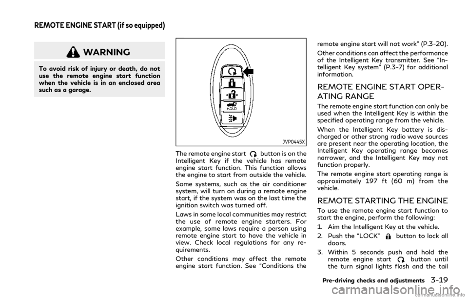
JVP0445X
The remote engine startbutton is on the
Intelligent Key if the vehicle has remote
engine start function. This function allows
the engine to start from outside the vehicle.
Some systems, such as the air conditioner
system, will turn on during a remote engine
start, if the system was on the last time the
ignition switch was turned off.
Laws in some local communities may restrict
the use of remote engine starters. For
example, some laws require a person using
remote engine start to have the vehicle in
view. Check local regulations for any re-
quirements.
Other conditions may affect the remote
engine start function. See “Conditions the remote engine start will not work” (P.3-20).
Other conditions can affect the performance
of the Intelligent Key transmitter. See “In-
telligent Key system” (P.3-7) for additional
information.
REMOTE ENGINE START OPER-
ATING RANGE
The remote engine start function can only be
used when the Intelligent Key is within the
specified operating range from the vehicle.
When the Intelligent Key battery is dis-
charged or other strong radio wave sources
are present near the operating location, the
Intelligent Key operating range becomes
narrower, and the Intelligent Key may not
function properly.
The remote engine start operating range is
approximately 197 ft (60 m) from the
vehicle.
REMOTE STARTING THE ENGINE
To use the remote engine start function to
start the engine, perform the following:
1. Aim the Intelligent Key at the vehicle.
2. Push the “LOCK”
button to lock all
doors.
3. Within 5 seconds push and hold the remote engine start
button until
the turn signal lights flash and the tail
Pre-driving checks and adjustments3-19
REMOTE ENGINE START (if so equipped)
Page 226 of 529

4 Monitor, climate, audio, phone and voice re-cognition systems
INFINITI InTouchTMOwner’s Manual ........................ 4-2
Safety note ........................................................................\
. 4-2
Around View
®Monitor ................................................... 4-3
Around View®Monitor system operation ........... 4-4
Around View®Monitor settings ........................... 4-12
Around View®Monitor system limitations ........ 4-14
System maintenance ................................................ 4-16
Camera aiding sonar function ..................................... 4-17 Sonar system operation .......................................... 4-18
Turning on and off the sonar function ............... 4-18
Sonar system limitations ......................................... 4-21
System maintenance ................................................ 4-21
Moving Object Detection (MOD) .............................. 4-22
MOD system operation ........................................... 4-23
Turning on and off the MOD system ................. 4-24
MOD system limitations ......................................... 4-25 System maintenance .............................................. 4-26
Ventilators ........................................................................\
4-27 Center ventilators ................................................... 4-27
Side ventilators ........................................................ 4-27
Rear ventilators ....................................................... 4-27
Heater and air conditioner ......................................... 4-28
Automatic air conditioner ..................................... 4-29
Rear automatic air conditioning system ........... 4-33
Operating tips .......................................................... 4-36
In-cabin microfilter ................................................. 4-36
Servicing climate control ....................................... 4-37
Antenna ........................................................................\
.... 4-37 Window antenna ..................................................... 4-37
Satellite antenna .................................................... 4-38
Car phone or CB radio ................................................ 4-38
Page 227 of 529

4-2Monitor, climate, audio, phone and voice recognition systems
Refer to the INFINITI InTouchTMOwner’s
Manual that includes the following informa-
tion.
. Navigation system
. Audio system
. Bluetooth
®Hands-Free Phone System
. Apple CarPlay®
.Android AutoTM
.INFINITI InTouchTMServices
. SiriusXM TrafficTM
.SiriusXM®Travel Link
. SiriusXM®Radio
. Viewing information
. Other settings
. Voice recognition
. Meter settings
. General system information
WARNING
.Do not disassemble or modify this
system. If you do, it may result in
accidents, fire, or electric shock.
. Do not use this system if you notice
any abnormality, such as a frozen
screen or lack of sound. Continued
use of the system may result in
accident, fire or electric shock.
. In case you notice any foreign object
in the system hardware, spill liquid on
it, or notice smoke or smell coming
from it, stop using the system im-
mediately. It is recommended you
visit an INFINITI retailer for servi-
cing. Ignoring such conditions may
lead to accidents, fire, or electric
shock.
. Park the vehicle in a safe location and
apply the parking brake to view the
images on the touch screen display.
Do not attempt to operate the system in
extreme temperature conditions [below
−4°F (−20°C) and above 158°F (70°C)].
Operating this system under these condi-
tions may result in system malfunctions.
INFINITI INTOUCHTMOWNER’S MANUALSAFETY NOTE
Page 263 of 529

4-38Monitor, climate, audio, phone and voice recognition systems
SAA3602
SATELLITE ANTENNA
There is a satellite antenna on the rear part
of the vehicle roof.When installing a car phone or a CB radio in
your vehicle, be sure to observe the follow-
ing cautions, otherwise the new equipment
may adversely affect the electronic control
modules and electronic control system har-
ness.
WARNING
.
A cellular phone should not be used
for any purpose while driving so full
attention may be given to vehicle
operation. Some jurisdictions prohibit
the use of cellular phones while
driving.
. If you must make a call while your
vehicle is in motion, the hands-free
cellular phone operational mode (if so
equipped) is highly recommended.
Exercise extreme caution at all times
so full attention may be given to
vehicle operation.
. If a conversation in a moving vehicle
requires you to take notes, pull off
the road to a safe location and stop
your vehicle before doing so.
CAUTION
.Keep the antenna as far away as
possible from the electronic control
modules.
. Keep the antenna wire more than 8 in
(20 cm) away from the electronic
control system harness. Do not route
the antenna wire next to any harness.
. Adjust the antenna standing-wave
ratio as recommended by the manu-
facturer.
. Connect the ground wire from the CB
radio chassis to the body.
. For details, it is recommended you
visit an INFINITI retailer.
CAR PHONE OR CB RADIO
Page 270 of 529

cause a malfunction of the tire pres-
sure sensors.
CAUTION
.The TPMS may not function properly
when the wheels are equipped with
tire chains or the wheels are buried in
snow.
. Do not place metalized film or any
metal parts (antenna, etc.) on the
windows. This may cause poor recep-
tion of the signals from the tire
pressure sensors, and the TPMS will
not function properly.
Some devices and transmitters may tem-
porarily interfere with the operation of the
TPMS and cause the low tire pressure
warning light to illuminate. Some examples
are:
. Facilities or electric devices using similar
radio frequencies are near the vehicle.
. If a transmitter set to similar frequencies
is being used in or near the vehicle.
. If a computer (or similar equipment) or a
DC/AC converter is being used in or near
the vehicle.
Low tire pressure warning light may illumi- nate in the following cases.
.
If the vehicle is equipped with a wheel
and tire without TPMS.
. If the TPMS has been replaced and the ID
has not been registered.
. If the wheel is not originally specified by
INFINITI.
FCC Notice:
For USA:
This device complies with Part 15 of the
FCC Rules. Operation is subject to the
following two conditions: (1) This device
may not cause harmful interference, and (2)
this device must accept any interference
received, including interference that may
cause undesired operation.
Note: Changes or modifications not ex-
pressly approved by the party responsible
for compliance could void the user’s author-
ity to operate the equipment.
For Canada:
This device complies with Industry Canada
licence-exempt RSS standard(s). Operation
is subject to the following two conditions:
(1) this device may not cause interference,
and (2) this device must accept any inter-
ference, including interference that may
cause undesired operation of the device.
TPMS with Tire Inflation Indicator
When adding air to an under-inflated tire,
the TPMS with Tire Inflation Indicator
provides visual and audible signals outside
the vehicle to help you inflate the tires to the
recommended COLD tire pressure.
Vehicle set-up:
1. Park the vehicle in a safe and level place.
2. Apply the parking brake and place the shift lever in the P (Park) position.
3. Place the ignition switch in the ON position. Do not start the engine.
Operation:
1. Add air to the tire.
2. After a few seconds, the hazard indica- tors will start flashing.
3. When the designated pressure is reached, the horn beeps once and the
hazard indicators stop flashing.
4. Perform the above steps for each tire.
. If the tire is over-inflated more than
approximately 4 psi (30 kPa), the horn
beeps and the hazard indicators flash 3
times. To correct the pressure, push the
core of the valve stem on the tire briefly
to release pressure. When the pressure
reaches the designated pressure, the
horn beeps once.
Starting and driving5-7
Page 276 of 529

SSD1021
When the ignition switch is pushed without
depressing the brake pedal, the ignition
switch position will change as follows:
.Push center once to change to ACC.
. Push center two times to change to ON.
. Push center three times to change to
OFF. (No position illuminates.)
. Push center four times to return to ACC.
. Open or close any door to return to
LOCK during the OFF position.
The ignition lock is designed so that the
ignition switch position cannot be switched
to LOCK until the shift lever is moved to the
P (Park) position.
When the ignition switch cannot be pushed
toward the LOCK position, proceed as follows:
1. Move the shift lever into the P (Park)
position.
2. Push the ignition switch to the OFF position. The ignition switch position
indicator will not illuminate.
3. Open the door. The ignition switch will change to the LOCK position.
The shift lever can be moved from the P
(Park) position if the ignition switch is in the
ON position and the brake pedal is de-
pressed.
If the battery of the vehicle is discharged,
the push-button ignition switch cannot be
turned from the LOCK position.
Some indicators and warnings for operation
are displayed on the vehicle information
display between the speedometer and tach-
ometer. (See “Vehicle information display”
(P.2-20).)
PUSH-BUTTON IGNITION
SWITCH POSITIONS
LOCK (Normal parking position)
The ignition switch can only be locked in this
position.
The ignition switch will be unlocked when it
is pushed to the ACC position while carrying
the Intelligent Key.
ACC (Accessories)
This position activates electrical accessories
such as the radio, when the engine is not
running.
ACC has a battery saver feature that will
turn the ignition switch to the OFF position
after a period of time under the following
conditions:
. all doors are closed.
. shift lever is in P (Park).
. turn signal/hazard indicator lights are
not flashing.
The battery saver feature will be cancelled if
any of the following occur:
. any door is opened.
. shift lever is moved out of P (Park).
. ignition switch changes position.
ON (Normal operating position)
This position turns on the ignition system
and electrical accessories.
ON has a battery saver feature that will turn
the ignition switch to the OFF position, if the
vehicle is not running, after some time under
the following conditions:
.all doors are closed.
. shift lever is in P (Park).
. turn signal/hazard indicator lights are
not flashing.
Starting and driving5-13
Page 282 of 529

WAF0350X
Shift lever
To move the shift lever,
: Push the button while depressing the brake pedal,
: Push the button,
: Just move the shift lever.
Shifting
The shift lever position indicator light (next
to the shift lever) will be illuminated for
approximately 30 minutes after the ignition
switch is turned off. The indicator light may
also illuminate when the vehicle receives
radio waves. This is not a malfunction.
After starting the engine, fully depress the
brake pedal and shift the shift lever from P (Park) to R (Reverse), N (Neutral), D (Drive)
or Manual shift mode position.
Push the button to shift into P (Park) or R
(Reverse). All other positions can be selected
without pushing the button.
WARNING
Apply the parking brake if the shift lever
is in any position while the engine is not
running. Failure to do so could cause the
vehicle to move unexpectedly or roll
away and result in serious personal
injury or property damage.
CAUTION
Make sure the vehicle is completely
stopped and the transmission is in the
P (Park) position.
P (Park) position:
Use this position when the vehicle is parked
or when starting the engine. Make sure the
vehicle is completely stopped. The brake
pedal must be depressed and the shift lever
button pushed in to move the shift lever
from the N (Neutral) position or any drive position to the P (Park) position.
Apply the
parking brake. When parking on a hill, apply
the parking brake first, then move the shift
lever to the P (Park) position.
CAUTION
Use this position only when the vehicle is
completely stopped.
R (Reverse):
Use this position to back up. Always be sure
the vehicle is completely stopped before
selecting the R (Reverse) position. The brake
pedal must be depressed and the shift lever
button pushed in to move the shift lever
from the P (Park) position, the N (Neutral)
position or any drive position to the R
(Reverse) position.
N (Neutral):
Neither forward nor reverse gear is engaged.
The engine can be started in this position.
You may shift to the N (Neutral) position and
restart a stalled engine while the vehicle is
moving.
D (Drive):
Use this position for all normal forward
driving.
Starting and driving5-19
Page 303 of 529

5-40Starting and driving
SYSTEM MALFUNCTION
When the system malfunctions, it will be
turned off automatically. The “Malfunction”
warning message and the BSW indicator
(orange) will appear in the vehicle informa-
tion display.
Action to take:
Stop the vehicle in a safe location, place the
vehicle in the P (Park) position, turn the
engine off and restart the engine.
If the message and BSW indicator (orange)
continues to appear, have the system
checked. It is recommended you visit an
INFINITI retailer for this service.
JVS1146X
SYSTEM MAINTENANCE
The two radar sensorsfor the BSW
system are located near the rear bumper.
Always keep the area near the radar sensors
clean.
The radar sensors may be blocked by
temporary ambient conditions such as
splashing water, mist or fog.
The blocked condition may also be caused by
objects such as ice, frost or dirt obstructing
the radar sensors.
Check for and remove objects obstructing
the area around the radar sensors.
Do not attach stickers (including transparent
material), install accessories or apply addi- tional paint near the radar sensors.
Do not strike or damage the area around the
radar sensors.
It is recommended you visit an INFINITI
retailer if the area around the radar sensors
is damaged due to a collision.
Radio frequency statement
For USA:
FCC ID: OAYSRR3B
This device complies with Part 15 of the FCC
Rules. Operation is subject to the following
two conditions:
(1) this device may not cause harmful interference, and
(2) this device must accept any interfer- ence received, including interference
that may cause undesired operation.
CAUTION TO USERS
Changes or modifications not expressly
approved by the party responsible for com-
pliance could void the user’s authority to
operate the equipment.
For Canada:
This device complies with Industry Canada
licence-exempt RSS standard(s). Operation
is subject to the following two conditions: (1)
this device may not cause interference, and
(2) this device must accept any interference,
Page 304 of 529

including interference that may cause un-
desired operation of the device.
Frequency bands: 24.05 – 24.25 Ghz
The field strength of SRR3-B is below 250
millivolts/m measured at 3 metres with an
average detector.
This device contains licence-exempt trans-
mitter(s)/receiver(s) that comply with Inno-
vation, Science and Economic Development
Canada’s licence-exempt RSS(s). Operation
is subject to the following two conditions:
1. This device may not cause interference.
2. This device must accept any interference,
including interference that may cause un-
desired operation of the device.
Radiofrequency radiation exposure informa-
tion:
This equipment complies with radiation ex-
posure limits set forth for an uncontrolled
environment. This equipment should be in-
stalled and operated with minimum distance
of 20 cm between the radiator and your
body.
WARNING
Failure to follow the warnings and
instructions for proper use of the BSI
system could result in serious injury or
death.
.The BSI system is not a replacement
for proper driving procedures and is
not designed to prevent contact with
vehicles or objects. When changing
lanes, always use the side and rear
mirrors and turn and look in the
direction your vehicle will move to
ensure it is safe to change lanes.
Never rely solely on the BSI system.
. There is a limitation to the detection
capability of the radar. Not every
moving object or vehicle will be
detected. Using the BSI system under
some road, ground, lane marker,
traffic or weather conditions could
lead to improper system operation.
Always rely on your own operation to
avoid accidents.
The BSI system helps alert the driver of other
vehicles in adjacent lanes when changing
lanes and helps assist the driver to return the
vehicle to the center of the traveling lane.
JVS1149X
The BSI system uses radar sensorsinstalled near the rear bumper to detect
other vehicles in an adjacent lane. In addition
to the radar sensors, the BSI system uses a
camera
installed behind the windshield to
monitor the lane markers of your traveling
lane.
Starting and driving5-41
BLIND SPOT INTERVENTION®
(BSI) (if so equipped)