brake INFINITI QX80 2021 Owner's Guide
[x] Cancel search | Manufacturer: INFINITI, Model Year: 2021, Model line: QX80, Model: INFINITI QX80 2021Pages: 529, PDF Size: 2.05 MB
Page 203 of 529

3-20Pre-driving checks and adjustments
lights illuminate. If the vehicle is not
within view, push and hold the remote
engine start
button for at least 2
seconds.
The following events will occur when the
engine starts:
. The front parking lights will turn on and
remain on as long as the engine is
running.
. The doors will be locked and the air
conditioner system may turn on.
. The engine will continue to run for about
10 minutes. Repeat the steps to extend
the time for an additional 10 minutes.
See “Extending engine run time” (P.3-
20).
Depress and hold the brake pedal, then place
the ignition switch in the ON position before
driving. For further instructions, see “Driving
the vehicle” (P.5-17).
EXTENDING ENGINE RUN TIME
The remote engine start function can be
extended one time by performing the steps
listed in “Remote starting the engine” (P.3-
19). Run time will be calculated as follows:
. The first 10 minute run time will start
when the remote engine start function is
performed.
. The second 10 minutes will start imme-
diately when the remote engine start function is performed. For example, if
the engine has been running for 5
minutes, and 10 minutes are added, the
engine will run for a total of 15 minutes.
. Extending engine run time will count
towards the two remote engine start
limit.
A maximum of two remote engine starts, or
a single start with an extension, are allowed
between ignition cycles.
The ignition switch must be cycled to the ON
position and then back to the OFF position
before the remote engine start procedure
can be used again.
CANCELING A REMOTE ENGINE
START
To cancel a remote engine start, perform one
of the following:
. Aim the Intelligent Key at the vehicle and
push and hold the remote engine start
button until the front parking lights
turn off.
. Turn on the hazard indicator flashers.
. Cycle the ignition switch ON and then
OFF.
. The extended engine run time has ex-
pired.
. The first 10 minute timer has expired. .
The engine hood has been opened.
. The shift lever is moved out of the P
(Park) position.
. The theft alarm sounds due to illegal
entry into the vehicle.
. The ignition switch is pushed without an
Intelligent Key in the vehicle.
. The ignition switch is pushed with an
Intelligent Key in the vehicle but the
brake pedal is not depressed.
CONDITIONS THE REMOTE EN-
GINE START WILL NOT WORK
The remote engine start will not operate if
any of the following conditions are present:
. The ignition switch is placed in the ON
position.
. The hood is not securely closed.
. The hazard indicator flashers are on.
. The engine is still running. The engine
must be completely stopped. Wait at
least 6 seconds if the engine goes from
running to off. This is not applicable
when extending engine run time.
. The remote engine start
button is
not pushed and held for at least 2
seconds.
. The remote engine start
button is
not pushed and held within 5 seconds of
pushing the “LOCK”
button.
Page 204 of 529
.The brake pedal is depressed.
. The doors are not closed and locked.
. The liftgate is open.
. An Intelligent Key warning message is
displayed in the vehicle information dis-
play.
. An Intelligent Key is left inside the
vehicle.
. The theft alarm sounds due to illegal
entry into the vehicle.
. Two remote engine starts, or a single
remote engine start with an extension,
have already been used.
. The shift lever is not in the P (Park)
position.
The remote engine start may display a
warning or indicator in the vehicle informa-
tion display. For an explanation of the
warning or indicator, see “Operational in-
dicators” (P.2-24).
JVP0567X
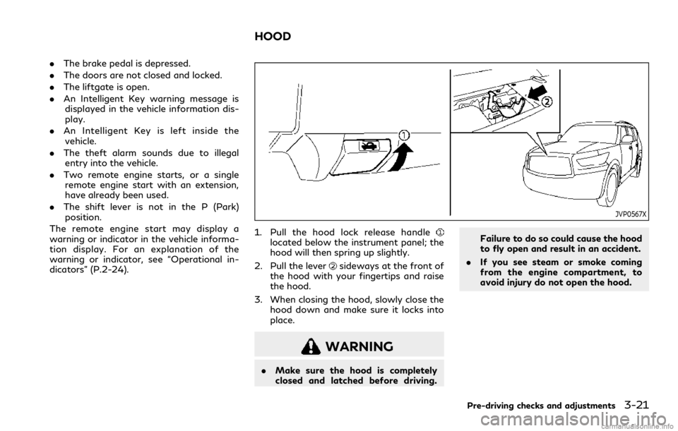
1. Pull the hood lock release handlelocated below the instrument panel; the
hood will then spring up slightly.
2. Pull the lever
sideways at the front of
the hood with your fingertips and raise
the hood.
3. When closing the hood, slowly close the hood down and make sure it locks into
place.
WARNING
.Make sure the hood is completely
closed and latched before driving. Failure to do so could cause the hood
to fly open and result in an accident.
. If you see steam or smoke coming
from the engine compartment, to
avoid injury do not open the hood.
Pre-driving checks and adjustments3-21
HOOD
Page 227 of 529
4-2Monitor, climate, audio, phone and voice recognition systems
Refer to the INFINITI InTouchTMOwner’s
Manual that includes the following informa-
tion.
. Navigation system
. Audio system
. Bluetooth
®Hands-Free Phone System
. Apple CarPlay®
.Android AutoTM
.INFINITI InTouchTMServices
. SiriusXM TrafficTM
.SiriusXM®Travel Link
. SiriusXM®Radio
. Viewing information
. Other settings
. Voice recognition
. Meter settings
. General system information
WARNING
.Do not disassemble or modify this
system. If you do, it may result in
accidents, fire, or electric shock.
. Do not use this system if you notice
any abnormality, such as a frozen
screen or lack of sound. Continued
use of the system may result in
accident, fire or electric shock.
. In case you notice any foreign object
in the system hardware, spill liquid on
it, or notice smoke or smell coming
from it, stop using the system im-
mediately. It is recommended you
visit an INFINITI retailer for servi-
cing. Ignoring such conditions may
lead to accidents, fire, or electric
shock.
. Park the vehicle in a safe location and
apply the parking brake to view the
images on the touch screen display.
Do not attempt to operate the system in
extreme temperature conditions [below
−4°F (−20°C) and above 158°F (70°C)].
Operating this system under these condi-
tions may result in system malfunctions.
INFINITI INTOUCHTMOWNER’S MANUALSAFETY NOTE
Page 236 of 529
WAE0290X
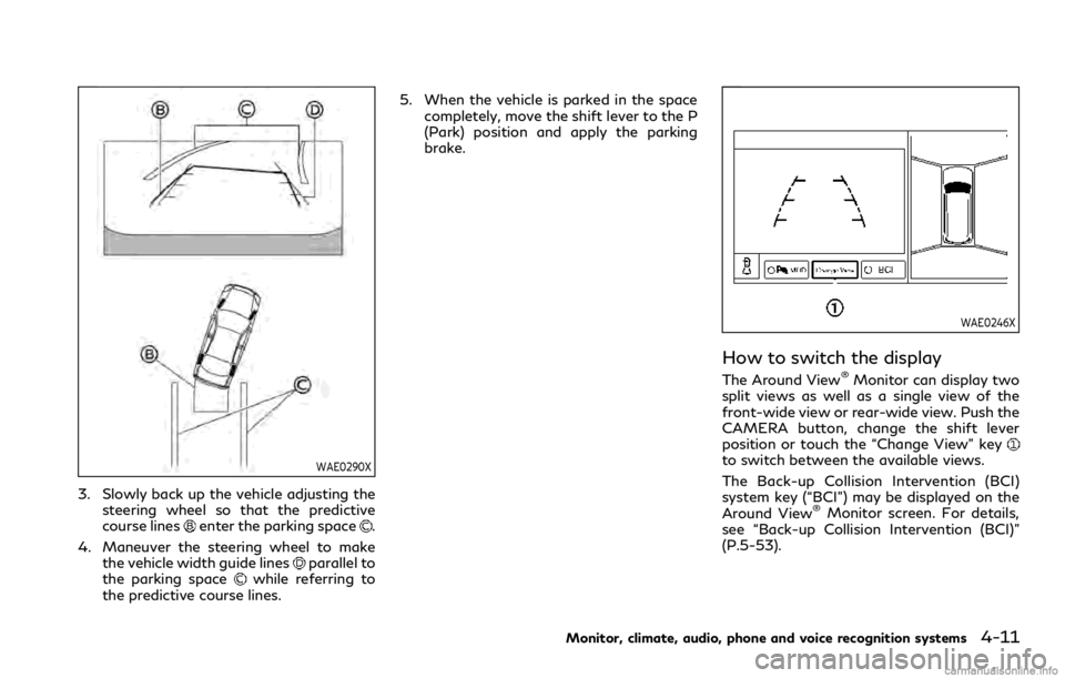
3. Slowly back up the vehicle adjusting thesteering wheel so that the predictive
course lines
enter the parking space.
4. Maneuver the steering wheel to make the vehicle width guide lines
parallel to
the parking spacewhile referring to
the predictive course lines. 5. When the vehicle is parked in the space
completely, move the shift lever to the P
(Park) position and apply the parking
brake.
WAE0246X
How to switch the display
The Around View®Monitor can display two
split views as well as a single view of the
front-wide view or rear-wide view. Push the
CAMERA button, change the shift lever
position or touch the “Change View” key
to switch between the available views.
The Back-up Collision Intervention (BCI)
system key (“BCI”) may be displayed on the
Around View
®Monitor screen. For details,
see “Back-up Collision Intervention (BCI)”
(P.5-53).
Monitor, climate, audio, phone and voice recognition systems4-11
Page 238 of 529

Available setting items:
Setting itemAction
Camera BCI Turn the Back-up Collision Intervention (BCI) system on/off. (See “Back-up
Collision Intervention (BCI)” (P.5-53).)
MOD Turn the MOD system on/off. (See “Moving Object Detection (MOD)” (P.4-
22).)
MOD Volume The volume setting of the MOD detection warning chime can be adjusted.
Unviewable Area Reminder When this item is turned on, the unviewable area is highlighted in yellow for
several seconds after the bird’s-eye view is displayed for the first time when the
ignition switch is placed in the ON position.
Predictive Course Lines When this item is turned on, the predictive course lines are displayed in the
front, rear and bird’s-eye view screen.
Auto Show Sonar Image The automatic sonar display can be turned on/off.
Display Settings
(Available only
when camera screen
is displayed on the
upper display.) Brightness
Adjust display settings by touching the “+”/“-” key.
Contrast
Tint
Color
Black Level
NOTE:
Do not adjust any of the Around View®Monitor settings while the vehicle is moving. Make sure the parking brake is firmly applied.
Monitor, climate, audio, phone and voice recognition systems4-13
Page 245 of 529

4-20Monitor, climate, audio, phone and voice recognition systems
Available setting items:
Setting itemAction
Parking Sonar Parking Sonar When this item is turned on, the front and rear sonar is activated.
When this item is turned off (indicator turns off), the front and rear sonar is
deactivated. The amber markers are displayed at the corners of the vehicle icon.
When the Around View
®Monitor is activated next time after placing the
ignition switch in the ON position, a gray sonar icon will briefly flash on the
upper display, indicating that the sonar system is off.
Auto Show Sonar Image When the sonar detects an object while this item is turned on, the Around View
®
Monitor will interrupt the current view in the display to show the surround area
of the vehicle.
Front Only When this item is turned on, only the front sonar is activated. The amber markers are displayed at the rear corners of the vehicle icon.
Distance Adjust the sensitivity level of the sonar.
Volume Adjust the tone volume of the sonar.
NOTE:
Do not adjust any of the Parking Sonar settings while the vehicle is moving. Make sure the parking brake is firmly applied.
Page 246 of 529
SONAR SYSTEM LIMITATIONS
WARNING
Listed below are the system limitations
for the sonar function. Failure to operate
the vehicle in accordance with these
system limitations could result in serious
injury or death.
.Inclement weather or ultrasonic
sources such as an automatic car
wash, a truck’s compressed-air
brakes or a pneumatic drill may affect
the function of the system, including
reduced performance or a false acti-
vation.
. The system is not designed to pre-
vent contact with small or moving
objects.
. The system will not detect small
objects below the bumper, and may
not detect objects close to the bum-
per or on the ground.
. The system may not detect the
following objects:
— Fluffy objects such as snow, cloth, cotton, grass or wool.
— Thin objects such as rope, wire or chain. — Wedge-shaped objects.
. If your vehicle sustains damage to the
bumper fascia, leaving it misaligned
or bent, the sensing zone may be
altered causing inaccurate measure-
ment of objects or false alarms.
CAUTION
Excessive noise (such as audio system
volume or an open vehicle window) will
interfere with the tone and it may not be
heard.
System temporarily unavailable
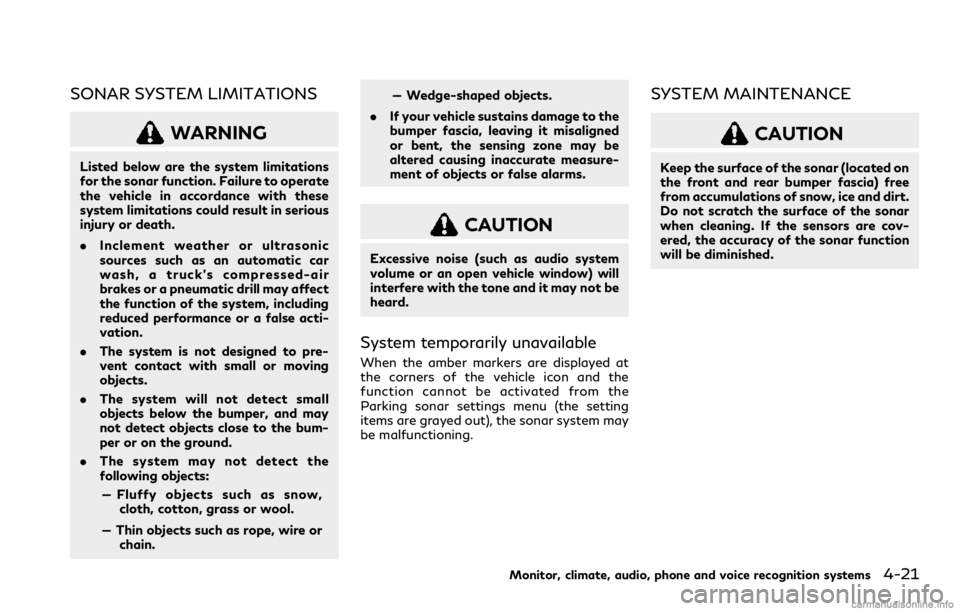
When the amber markers are displayed at
the corners of the vehicle icon and the
function cannot be activated from the
Parking sonar settings menu (the setting
items are grayed out), the sonar system may
be malfunctioning.
SYSTEM MAINTENANCE
CAUTION
Keep the surface of the sonar (located on
the front and rear bumper fascia) free
from accumulations of snow, ice and dirt.
Do not scratch the surface of the sonar
when cleaning. If the sensors are cov-
ered, the accuracy of the sonar function
will be diminished.
Monitor, climate, audio, phone and voice recognition systems4-21
Page 264 of 529

5 Starting and driving
Precautions when starting and driving ...................... 5-4Exhaust gas (carbon monoxide) .............................. 5-4
Three-way catalyst ..................................................... 5-4
Tire Pressure Monitoring System (TPMS) ........... 5-5
Avoiding collision and rollover ................................. 5-8
On-pavement and off-road
driving precautions ..................................................... 5-8
Off-road recovery ....................................................... 5-9
Rapid air pressure loss ............................................... 5-9
About lowering of the rear of the vehicle ......... 5-10
Drinking alcohol/drugs and driving ..................... 5-10
Driving safety precautions ..................................... 5-10
Push-button ignition switch ........................................ 5-12
Operating range for engine start function ........ 5-12
Push-button ignition switch positions ................ 5-13
Emergency engine shut off .................................... 5-14
Intelligent Key battery discharge .......................... 5-14
Before starting the engine ........................................... 5-15
Starting the engine ......................................................... 5-15 Remote start (if so equipped) ................................ 5-16
Driving the vehicle .......................................................... 5-17 Engine protection mode .......................................... 5-17
Automatic transmission ........................................... 5-18
Parking brake ................................................................... 5-22 Lane Departure Warning (LDW)/Lane Departure
Prevention (LDP) (if so equipped) ............................. 5-22
LDW system operation ......................................... 5-24
Turning the LDW system ON/OFF ................... 5-25
How to enable/disable the LDW system ........ 5-26
LDP system operation (if so equipped) ............ 5-26
Turning the LDP system ON/OFF (if
so equipped) ............................................................. 5-27
How to enable/disable the LDP system (if
so equipped) ............................................................. 5-28
LDW/LDP (if so equipped)
system limitations ................................................... 5-28
System temporarily unavailable .......................... 5-29
System malfunction ............................................... 5-30
System maintenance ............................................. 5-30
Blind Spot Warning (BSW) ......................................... 5-31
BSW system operation .......................................... 5-33
Turning the BSW system ON/OFF ................... 5-34
How to enable/disable the BSW system ......... 5-34
BSW system limitations ........................................ 5-35
BSW driving situations .......................................... 5-36
System temporarily unavailable .......................... 5-39
System malfunction ............................................... 5-40
System maintenance ............................................. 5-40
Page 266 of 529

4WD shift switch .................................................... 5-117
4WD shift indicator ................................................ 5-118
4WD warning light ................................................. 5-118
Hill Start Assist system .............................................. 5-120
Parking/parking on hills .............................................. 5-121
TOW mode ..................................................................... 5-122
SNOW mode .................................................................. 5-122
Power steering .............................................................. 5-123
Brake system .................................................................. 5-123 Braking precautions ................................................ 5-123
Parking brake break-in .......................................... 5-123
Brake assist ................................................................... 5-124 Brake assist .............................................................. 5-124
Anti-lock Braking System (ABS) ........................ 5-124 Vehicle Dynamic Control (VDC) system ................ 5-125
Vehicle Dynamic Control (VDC)
OFF switch ............................................................. 5-127
Cold weather driving .................................................. 5-128
Freeing a frozen door lock ................................ 5-128
Antifreeze ............................................................... 5-128
Battery .................................................................... 5-128
Draining of coolant water ................................. 5-128
Tire equipment ...................................................... 5-128
Special winter equipment .................................. 5-128
Driving on snow or ice ........................................ 5-128
Engine block heater (if so equipped) ............... 5-129
Page 270 of 529
cause a malfunction of the tire pres-
sure sensors.
CAUTION
.The TPMS may not function properly
when the wheels are equipped with
tire chains or the wheels are buried in
snow.
. Do not place metalized film or any
metal parts (antenna, etc.) on the
windows. This may cause poor recep-
tion of the signals from the tire
pressure sensors, and the TPMS will
not function properly.
Some devices and transmitters may tem-
porarily interfere with the operation of the
TPMS and cause the low tire pressure
warning light to illuminate. Some examples
are:
. Facilities or electric devices using similar
radio frequencies are near the vehicle.
. If a transmitter set to similar frequencies
is being used in or near the vehicle.
. If a computer (or similar equipment) or a
DC/AC converter is being used in or near
the vehicle.
Low tire pressure warning light may illumi- nate in the following cases.
.
If the vehicle is equipped with a wheel
and tire without TPMS.
. If the TPMS has been replaced and the ID
has not been registered.
. If the wheel is not originally specified by
INFINITI.
FCC Notice:
For USA:
This device complies with Part 15 of the
FCC Rules. Operation is subject to the
following two conditions: (1) This device
may not cause harmful interference, and (2)
this device must accept any interference
received, including interference that may
cause undesired operation.
Note: Changes or modifications not ex-
pressly approved by the party responsible
for compliance could void the user’s author-
ity to operate the equipment.
For Canada:
This device complies with Industry Canada
licence-exempt RSS standard(s). Operation
is subject to the following two conditions:
(1) this device may not cause interference,
and (2) this device must accept any inter-
ference, including interference that may
cause undesired operation of the device.
TPMS with Tire Inflation Indicator
When adding air to an under-inflated tire,
the TPMS with Tire Inflation Indicator
provides visual and audible signals outside
the vehicle to help you inflate the tires to the
recommended COLD tire pressure.
Vehicle set-up:
1. Park the vehicle in a safe and level place.
2. Apply the parking brake and place the shift lever in the P (Park) position.
3. Place the ignition switch in the ON position. Do not start the engine.
Operation:
1. Add air to the tire.
2. After a few seconds, the hazard indica- tors will start flashing.
3. When the designated pressure is reached, the horn beeps once and the
hazard indicators stop flashing.
4. Perform the above steps for each tire.
. If the tire is over-inflated more than
approximately 4 psi (30 kPa), the horn
beeps and the hazard indicators flash 3
times. To correct the pressure, push the
core of the valve stem on the tire briefly
to release pressure. When the pressure
reaches the designated pressure, the
horn beeps once.
Starting and driving5-7