warning light INFINITI QX80 2023 Workshop Manual
[x] Cancel search | Manufacturer: INFINITI, Model Year: 2023, Model line: QX80, Model: INFINITI QX80 2023Pages: 590, PDF Size: 2.57 MB
Page 205 of 590

call attention as follows:
1. Push the PANIC
buttonon the
Intelligent Key for more than 1 second.
2. The theft warning alarm and headlights will stay on for 25 seconds.
3. The panic alarm stops when:
.It has run for 25 seconds, or.Any of the buttons on the Intelligent Key are pushed. (Note: Panic button
or power liftgate button should be
pushed for more than 1 second.)
Remote engine start (if so equipped)
The remote engine startbuttonis on
the Intelligent Key if the vehicle has remote
engine start function. This function allows
the engine to start from outside the vehicle.
See “Remote engine start” (P.3-19).
Setting hazard indicator and horn
mode
This vehicle is set in hazard indicator and
horn mode when you first receive the vehicle.
In hazard indicator and horn mode, when the
LOCK
button is pushed, the hazard
indicator flashes twice and the horn chirps
once. When the UNLOCK
button is
pushed, the hazard indicator flashes once.
If horns are not necessary, the system can be
switched to the hazard indicator mode. In hazard indicator mode, when the LOCK
button is pushed, the hazard indicator
flashes twice. When the UNLOCK
button is pushed, neither the hazard indica-
tor nor the horn operates.
Pre-driving checks and adjustments3-17
Page 207 of 590

WARNING
To avoid risk of injury or death, do not
use the remote engine start function
when the vehicle is in an enclosed area
such as a garage.
JVP0445X
The remote engine startbutton is on the
Intelligent Key if the vehicle has remote
engine start function. This function allows
the engine to start from outside the vehicle.
Some systems, such as the air conditioner
system, will turn on during a remote engine
start, if the system was on the last time the
ignition switch was turned off.
Laws in some local communities may restrict
the use of remote engine starters. For
example, some laws require a person using
remote engine start to have the vehicle in
view. Check local regulations for any re-
quirements.
Other conditions may affect the remote
engine start function. See “Conditions the remote engine start will not work” (P.3-20).
Other conditions can affect the performance
of the Intelligent Key transmitter. See “In-
telligent Key system” (P.3-7) for additional
information.
REMOTE ENGINE START OPER-
ATING RANGE
The remote engine start function can only be
used when the Intelligent Key is within the
specified operating range from the vehicle.
When the Intelligent Key battery is dis-
charged or other strong radio wave sources
are present near the operating location, the
Intelligent Key operating range becomes
narrower, and the Intelligent Key may not
function properly.
The remote engine start operating range is
approximately 197 ft (60 m) from the
vehicle.
REMOTE STARTING THE ENGINE
To use the remote engine start function to
start the engine, perform the following:
1. Aim the Intelligent Key at the vehicle.
2. Push the “LOCK”
button to lock all
doors.
3. Within 5 seconds push and hold the remote engine start
button until
the turn signal lights flash and the tail
Pre-driving checks and adjustments3-19
REMOTE ENGINE START (if so equipped)
Page 209 of 590

.The brake pedal is depressed.
. The doors are not closed and locked.
. The liftgate is open.
. An Intelligent Key warning message is
displayed in the vehicle information dis-
play.
. An Intelligent Key is left inside the
vehicle.
. The theft alarm sounds due to illegal
entry into the vehicle.
. Two remote engine starts, or a single
remote engine start with an extension,
have already been used.
. The shift lever is not in the P (Park)
position.
The remote engine start may display a
warning or indicator in the vehicle informa-
tion display. For an explanation of the
warning or indicator, see “Operational in-
dicators” (P.2-28).
JVP0567X
1. Pull the hood lock release handlelocated below the instrument panel; the
hood will then spring up slightly.
2. Pull the lever
sideways at the front of
the hood with your fingertips and raise
the hood.
3. When closing the hood, slowly close the hood down and make sure it locks into
place.
WARNING
.Make sure the hood is completely
closed and latched before driving. Failure to do so could cause the hood
to fly open and result in an accident.
. If you see steam or smoke coming
from the engine compartment, to
avoid injury do not open the hood.
Pre-driving checks and adjustments3-21
HOOD
Page 215 of 590

sparks near the vehicle when refuel-
ing.
. Do not attempt to top off the fuel
tank after the fuel pump nozzle shuts
off automatically. Continued refuel-
ing may cause fuel overflow, resulting
in fuel spray and possibly a fire.
. Use only an original equipment type
fuel-filler cap as a replacement. It has
a built-in safety valve needed for
proper operation of the fuel system
and emission control system. An in-
correct cap can result in a serious
malfunction and possible injury. It
could also cause the malfunction
indicator light to come on.
. Never pour fuel into the throttle body
to attempt to start your vehicle.
. Do not fill a portable fuel container in
the vehicle or trailer. Static electricity
can cause an explosion of flammable
liquid, vapor or gas in any vehicle or
trailer. To reduce the risk of serious
injury or death when filling portable
fuel containers:
— Always place the container on the ground when filling.
— Do not use electronic devices when filling. — Keep the pump nozzle in contact
with the container while you are
filling it.
— Use only approved portable fuel containers for flammable liquid.
CAUTION
. If fuel is spilled on the vehicle body,
flush it away with water to avoid
paint damage.
. Insert the cap straight into the fuel-
filler tube, then tighten until the fuel-
filler cap clicks. Failure to tighten the
fuel-filler cap properly may cause the
malfunction indicator light (MIL)
to illuminate. If thelight illumi-
nates because the fuel-filler cap is
loose or missing, tighten or install the
cap and continue to drive the vehicle.
The
light should turn off after a
few driving trips. If thelight does
not turn off after a few driving trips,
have the vehicle inspected. It is
recommended you visit an INFINITI
retailer for this service.
. The Loose Fuel Cap warning will
appear if the fuel-filler cap is not
properly tightened. It may take a few driving trips for the message to be
displayed. Failure to tighten the fuel-
filler cap properly after the Loose
Fuel Cap warning appears may cause
the
Malfunction Indicator Light
(MIL) to illuminate.
Turn the cap counterclockwise to remove.
To tighten, turn the cap clockwise until a
single click is heard.
Pre-driving checks and adjustments3-27
Page 219 of 590

dicator light will turn off. Push the “I” switchto turn the system on.
Do not allow any object to cover the sensors
or apply glass cleaner on them. Doing so
will reduce the sensitivity of the sensor,
resulting in improper operation.
For the HomeLink
®Universal Transceiver
operation, see “HomeLink®Universal Trans-
ceiver (Type A)” (P.2-81).
Smart Rearview Mirror (if so
equipped)
WARNING
. Failure to follow the warnings and
instructions for proper use of the
Smart Rearview Mirror could result
in serious injury or death.
— The Smart Rearview Mirror is a convenience feature but it is not a
substitute for proper vehicle op-
eration. The system has areas
where objects cannot be viewed.
Check the blind spot of the Smart
Rearview Mirror before vehicle
operation. The driver is always
responsible for safe driving.
— Do not disassemble or modify the Smart Rearview Mirror, the cam- era unit or wirings. If you do, it
may result in accidents or fire. In
case you notice smoke or smell
coming from the Smart Rearview
Mirror, stop using the system
immediately. It is recommended
that you see an INFINITI retailer
for servicing.
— Do not operate the Smart Rear- view Mirror while driving. Doing
so can be a distraction and it could
lose control of your vehicle and
cause an accident or serious in-
jury.
— Do not gaze into the Smart Rear- view Mirror display during driv-
ing. It may cause a distraction and
it could lose control of your vehi-
cle and cause an accident or
serious injury.
— Do not put a cigarette or flames to the Smart Rearview Mirror, the
camera unit or wirings. It may
cause a fire.
. Be sure to adjust the Smart Rearview
Mirror before driving. Switch the
system to the conventional rearview
mirror mode and be properly seated
on the driver’s seat. Then adjust the
mirror so as to see the rear window properly. Driving without adjusting
the mirror may cause difficulty in
watching the display at Smart Rear-
view Mirror mode (camera view
mode) due to the reflection from the
surface of the mirror.
. If the Smart Rearview Mirror mal-
functions, immediately switch the
system to the conventional rearview
mirror mode.
. When strong light (for example, sun-
light or high beams from following
vehicles) enters the camera, a light
beam or a glaring light may appear on
the monitor screen of the Smart
Rearview Mirror. In that case, switch
the system to the conventional rear-
view mirror mode appropriately.
. If dirt, rain or snow accumulates on
the exterior glass surface covering
the camera, the Smart Rearview
Mirror may not display objects
clearly. Use of the rear window
wiper/washer may improve visibility,
but if not, switch the Smart Rearview
Mirror to the conventional rearview
mirror mode until a time the glass
covering the camera can be cleaned.
Pre-driving checks and adjustments3-31
Page 237 of 590

more, a line is displayed only on the
opposite side of the turn.
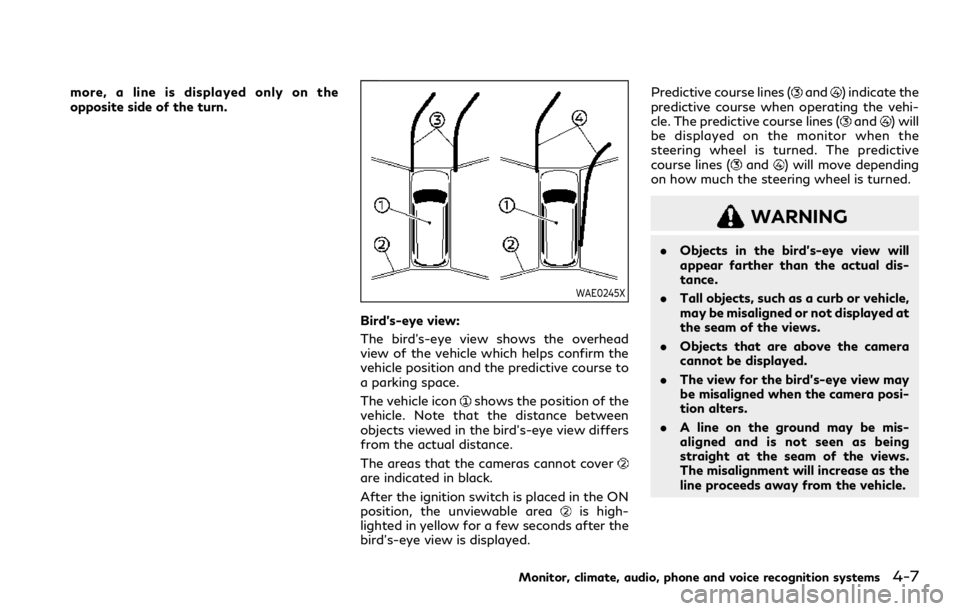
WAE0245X
Bird’s-eye view:
The bird’s-eye view shows the overhead
view of the vehicle which helps confirm the
vehicle position and the predictive course to
a parking space.
The vehicle icon
shows the position of the
vehicle. Note that the distance between
objects viewed in the bird’s-eye view differs
from the actual distance.
The areas that the cameras cannot cover
are indicated in black.
After the ignition switch is placed in the ON
position, the unviewable area
is high-
lighted in yellow for a few seconds after the
bird’s-eye view is displayed. Predictive course lines (
and) indicate the
predictive course when operating the vehi-
cle. The predictive course lines (
and) will
be displayed on the monitor when the
steering wheel is turned. The predictive
course lines (
and) will move depending
on how much the steering wheel is turned.
WARNING
. Objects in the bird’s-eye view will
appear farther than the actual dis-
tance.
. Tall objects, such as a curb or vehicle,
may be misaligned or not displayed at
the seam of the views.
. Objects that are above the camera
cannot be displayed.
. The view for the bird’s-eye view may
be misaligned when the camera posi-
tion alters.
. A line on the ground may be mis-
aligned and is not seen as being
straight at the seam of the views.
The misalignment will increase as the
line proceeds away from the vehicle.
Monitor, climate, audio, phone and voice recognition systems4-7
Page 255 of 590

at the same time.
To enable or disable the MOD system, use
the camera settings menu. See “MOD func-
tion settings” (P.4-25).
MOD FUNCTION SETTINGS
The MOD function settings can be changed
using the following procedures.
1. Push the MENU button on the INFINITIcontroller.
2. Touch the “Settings” key on the touch screen display.
3. Touch the “Camera” key.
4. Touch the “Camera” key.
Available setting items:
Moving Object Detection:
When this item is turned on, the MOD
system is activated. When this item is turned
off (indicator turns off), the MOD system is
deactivated.
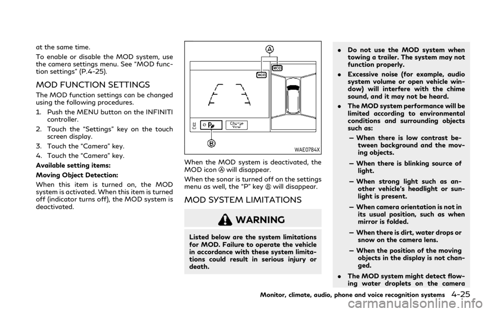
WAE0784X
When the MOD system is deactivated, the
MOD iconwill disappear.
When the sonar is turned off on the settings
menu as well, the “P” key
will disappear.
MOD SYSTEM LIMITATIONS
WARNING
Listed below are the system limitations
for MOD. Failure to operate the vehicle
in accordance with these system limita-
tions could result in serious injury or
death. .
Do not use the MOD system when
towing a trailer. The system may not
function properly.
. Excessive noise (for example, audio
system volume or open vehicle win-
dow) will interfere with the chime
sound, and it may not be heard.
. The MOD system performance will be
limited according to environmental
conditions and surrounding objects
such as:
— When there is low contrast be- tween background and the mov-
ing objects.
— When there is blinking source of light.
— When strong light such as an- other vehicle’s headlight or sun-
light is present.
— When camera orientation is not in its usual position, such as when
mirror is folded.
— When there is dirt, water drops or snow on the camera lens.
— When the position of the moving objects in the display is not chan-
ged.
. The MOD system might detect flow-
ing water droplets on the camera
Monitor, climate, audio, phone and voice recognition systems4-25
Page 274 of 590

4-44Monitor, climate, audio, phone and voice recognition systems
6.HDMI port
Connect an external audio/video source
using a full-size HDMI connector. Sup-
ports MHL 2.0 playback and charging.
7. USB 2.0 port
Play videos, music, and images stored on
most USB devices. Provides up to 2 amps
of output to charge most mobile devices.
8. Headphone output jack
Connect wired headphones using a 1/8
in (3.5 mm) stereo connector.
CAUTION
.Do not use any harsh solvents or
chemicals when cleaning the monitor.
. Do not use any abrasive cleaners that
may scratch the screen. Use only a
lightly dampened lint free cloth to
wipe the screen if it is dirty.
. The LCD display screen is not
touchscreen. Do not put pressure or
add suction cups on the screen.
. Caution children to avoid touching or
scratching the screen, as it may
become dirty or damaged.
. Place the monitor in the fully closed
position when not in use.
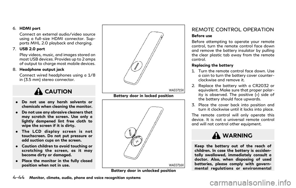
WAE0715X
Battery door in locked position
WAE0716X
Battery door in unlocked position
REMOTE CONTROL OPERATION
Before use
Before attempting to operate your remote
control, turn the remote control face down
and remove the battery insulator by pulling
the clear plastic tab away from the remote
control.
Replacing the battery
1. Turn the remote control face down. Use
a coin to turn the battery cover counter-
clockwise and remove it.
2. Replace the battery with a CR2032 or equivalent. Make sure that proper polar-
ity is observed. The positive (+) side of
the battery should face upwards.
3. Place the cover back into position and turn it clockwise until it locks into place.
The remote control will only operate this
device. It is not a universal remote control
and will not control other equipment.
WARNING
Keep the battery out of the reach of
children. In case the battery is acciden-
tally swallowed, immediately consult a
doctor. Also, when disposing of used
batteries, please comply with govern-
mental regulations or environmental
Page 307 of 590

Increasing fuel economy ............................................. 5-116
INFINITI all-mode 4WD®(if so equipped) ............ 5-116
INFINITI all-mode 4WD®system ....................... 5-117
4WD shift switch ................................................... 5-120
4WD shift indicator ................................................ 5-121
4WD warning light ................................................. 5-121
Hill Start Assist system ............................................... 5-123
Parking/parking on hills ............................................. 5-124
TOW mode ..................................................................... 5-125
SNOW mode .................................................................. 5-125
Front and rear sonar system ..................................... 5-126
System operation .................................................... 5-127
Sonar function settings ........................................ 5-128
Turning on and off the sonar function ............ 5-130
Sonar limitations ..................................................... 5-131
System temporarily unavailable .......................... 5-132
System maintenance .............................................. 5-132
Power steering .............................................................. 5-132 Brake system ................................................................. 5-133
Braking precautions .............................................. 5-133
Parking brake break-in ........................................ 5-133
Brake assist ................................................................... 5-134
Brake assist ............................................................ 5-134
Anti-lock Braking System (ABS) ...................... 5-134
Vehicle Dynamic Control (VDC) system ................ 5-135 Vehicle Dynamic Control (VDC)
OFF switch ............................................................. 5-137
Cold weather driving ................................................... 5-137 Freeing a frozen door lock ................................. 5-137
Antifreeze ................................................................ 5-137
Battery ..................................................................... 5-137
Draining of coolant water .................................. 5-137
Tire equipment ...................................................... 5-138
Special winter equipment .................................. 5-138
Driving on snow or ice ........................................ 5-138
Engine block heater (if so equipped) .............. 5-138
Page 310 of 590

5-6Starting and driving
not detect a sudden drop in tire pressure
(for example, a flat tire while driving).
. The low tire pressure warning light does
not automatically turn off when the tire
pressure is adjusted. After the tire is
inflated to the recommended pressure,
the vehicle must be driven at speeds
above 16 MPH (25 km/h) to activate the
TPMS and turn off the low tire pressure
warning light. Use a tire pressure gauge
to check the tire pressure.
. The “Tire Pressure Low Add Air” warning
appears in the vehicle information dis-
play when the low tire pressure warning
light is illuminated and low tire pressure
is detected. The “Tire Pressure Low Add
Air” warning turns off when the low tire
pressure warning light turns off.
The “Tire Pressure Low Add Air” warning
appears each time the ignition switch is
placed in the ON position as long as the
low tire pressure warning light remains
illuminated.
The “Tire Pressure Low Add Air” warning
does not appear if the low tire pressure
warning light illuminates to indicate a
TPMS malfunction.
. Tire pressure rises and falls depending on
the heat caused by the vehicle’s opera-
tion and the outside temperature. Do not
reduce the tire pressure after driving
because the tire pressure rises after driving. Low outside temperature can
lower the temperature of the air inside
the tire which can cause a lower tire
inflation pressure. This may cause the
low tire pressure warning light to illumi-
nate. If the warning light illuminates in
low ambient temperature, check the tire
pressure for all four tires.
. You can also check the pressure of all
tires (except the spare tire) on the vehicle
information display. (See “10. Tire pres-
sures” (P.2-36).)
For additional information, see “Low tire
pressure warning light” (P.2-16) and “Tire
Pressure Monitoring System (TPMS) ” (P.6-
3).
WARNING
. If the low tire pressure warning light
illuminates while driving, avoid sud-
den steering maneuvers or abrupt
braking, reduce vehicle speed, pull
off the road to a safe location and
stop the vehicle as soon as possible.
Driving with under-inflated tires may
permanently damage the tires and
increase the likelihood of tire failure.
Serious vehicle damage could occur
and may lead to an accident and
could result in serious personal injury. Check the tire pressure for all four
tires. Adjust the tire pressure to the
recommended COLD tire pressure
shown on the Tire and Loading
Information label to turn the low tire
pressure warning light OFF. If the
light still illuminates while driving
after adjusting the tire pressure, a
tire may be flat or the TPMS may be
malfunctioning. If you have a flat tire,
replace it with a spare tire as soon as
possible. If no tire is flat and all tires
are properly inflated, it is recom-
mended you consult an INFINITI
retailer.
. Since the spare tire is not equipped
with the TPMS, when a spare tire is
mounted or a wheel is replaced, the
TPMS will not function and the low
tire pressure warning light will flash
for approximately 1 minute. The light
will remain on after 1 minute. Have
your tires replaced and/or TPMS
system reset as soon as possible. It
is recommended you visit an INFINITI
retailer for these services.
. Replacing tires with those not origin-
ally specified by INFINITI could affect
the proper operation of the TPMS.
. Do not inject any tire liquid or aerosol
tire sealant into the tires, as this may