ISUZU AXIOM 2002 Service Owners Manual
Manufacturer: ISUZU, Model Year: 2002,
Model line: AXIOM,
Model: ISUZU AXIOM 2002
Pages: 2100, PDF Size: 19.35 MB
ISUZU AXIOM 2002 Service Owners Manual
AXIOM 2002
ISUZU
ISUZU
https://www.carmanualsonline.info/img/61/57174/w960_57174-0.png
ISUZU AXIOM 2002 Service Owners Manual
Trending: mileage, fuel cap, brake sensor, lights, OBD port, body and accessories, power steering fluid
Page 91 of 2100
HEATING, VENTILATION AND AIR CONDITIONING (HVAC)
1A±65
Circuit Diagram
D01R200010
Page 92 of 2100
1A±66
HEATING, VENTILATION AND AIR CONDITIONING (HVAC)
D01R200011
Page 93 of 2100
HEATING, VENTILATION AND AIR CONDITIONING (HVAC)
1A±67
D01R200003
Page 94 of 2100
1A±68
HEATING, VENTILATION AND AIR CONDITIONING (HVAC)
D01R200004
Page 95 of 2100
HEATING, VENTILATION AND AIR CONDITIONING (HVAC)
1A±69
D01R200009
Page 96 of 2100

1A±70
HEATING, VENTILATION AND AIR CONDITIONING (HVAC)
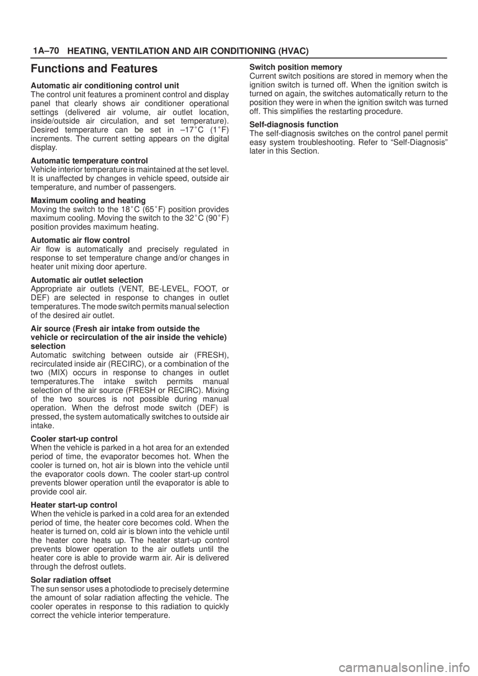
Functions and Features
Automatic air conditioning control unit
The control unit features a prominent control and display
panel that clearly shows air conditioner operational
settings (delivered air volume, air outlet location,
inside/outside air circulation, and set temperature).
Desired temperature can be set in ±17�C (1�F)
increments. The current setting appears on the digital
display.
Automatic temperature control
Vehicle interior temperature is maintained at the set level.
It is unaffected by changes in vehicle speed, outside air
temperature, and number of passengers.
Maximum cooling and heating
Moving the switch to the 18�C (65�F) position provides
maximum cooling. Moving the switch to the 32�C (90�F)
position provides maximum heating.
Automatic air flow control
Air flow is automatically and precisely regulated in
response to set temperature change and/or changes in
heater unit mixing door aperture.
Automatic air outlet selection
Appropriate air outlets (VENT, BE-LEVEL, FOOT, or
DEF) are selected in response to changes in outlet
temperatures. The mode switch permits manual selection
of the desired air outlet.
Air source (Fresh air intake from outside the
vehicle or recirculation of the air inside the vehicle)
selection
Automatic switching between outside air (FRESH),
recirculated inside air (RECIRC), or a combination of the
two (MIX) occurs in response to changes in outlet
temperatures.The intake switch permits manual
selection of the air source (FRESH or RECIRC). Mixing
of the two sources is not possible during manual
operation. When the defrost mode switch (DEF) is
pressed, the system automatically switches to outside air
intake.
Cooler start-up control
When the vehicle is parked in a hot area for an extended
period of time, the evaporator becomes hot. When the
cooler is turned on, hot air is blown into the vehicle until
the evaporator cools down. The cooler start-up control
prevents blower operation until the evaporator is able to
provide cool air.
Heater start-up control
When the vehicle is parked in a cold area for an extended
period of time, the heater core becomes cold. When the
heater is turned on, cold air is blown into the vehicle until
the heater core heats up. The heater start-up control
prevents blower operation to the air outlets until the
heater core is able to provide warm air. Air is delivered
through the defrost outlets.
Solar radiation offset
The sun sensor uses a photodiode to precisely determine
the amount of solar radiation affecting the vehicle. The
cooler operates in response to this radiation to quickly
correct the vehicle interior temperature.Switch position memory
Current switch positions are stored in memory when the
ignition switch is turned off. When the ignition switch is
turned on again, the switches automatically return to the
position they were in when the ignition switch was turned
off. This simplifies the restarting procedure.
Self-diagnosis function
The self-diagnosis switches on the control panel permit
easy system troubleshooting. Refer to ªSelf-Diagnosisº
later in this Section.
Page 97 of 2100
HEATING, VENTILATION AND AIR CONDITIONING (HVAC)
1A±71
Automatic Air Conditioner Block Diagram
F01R200004
Page 98 of 2100
1A±72
HEATING, VENTILATION AND AIR CONDITIONING (HVAC)
Control Panel Layout
865R200006
Legend
(1) Temperature Control Switch
(2) Auto Switch
(3) DEF Mode Switch
(4) Rr DEF Mode Switch(5) Intake Switch
(6) Mode Switch
(7) Air Conditioning Switch
(8) Fan Switch
(9) Off Switch
Page 99 of 2100
HEATING, VENTILATION AND AIR CONDITIONING (HVAC)
1A±73
Air Control Functions
C01R200013
Legend
(1) DEF Door
(2) Air Mix Door
(3) Evaporator Core
(4) Fresh Air Intake
(5) Interior Air Intake
(6) Blower Unit(7) Evaporator Unit
(8) Heater Core
(9) Heater Unit
(10) Sub Air Mix Door
(11) FOOT Door
(12) VENT Door
Page 100 of 2100

1A±74
HEATING, VENTILATION AND AIR CONDITIONING (HVAC)
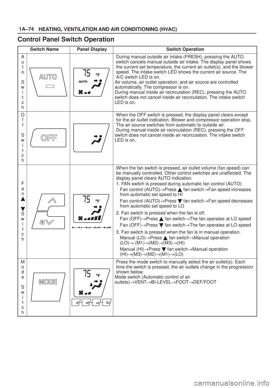
Control Panel Switch Operation
Switch NamePanel DisplaySwitch Operation
A
u
t
o
S
w
i
t
c
hDuring manual outside air intake (FRESH), pressing the AUTO
switch cancels manual outside air intake. The display panel shows
the current set temperature, the current air outlet(s), and the blower
speed. The intake switch LED shows the current air source. The
A/C switch LED is on.
Air volume, air outlet operation, and air source are controlled
automatically. The compressor is on.
During manual inside air recirculation (REC), pressing the AUTO
switch does not cancel inside air recirculation. The intake switch
LED is on.
O
f
f
S
w
i
t
c
hWhen the OFF switch is pressed, the display panel clears except
for the air outlet indication. Blower and compressor operation stop.
The air source switches from automatic to outside air.
During manual inside air recirculation (REC), pressing the OFF
switch does not cancel inside air recirculation. The intake switch
LED is on.
F
a
n
�
´
�
S
w
i
t
c
h
When the fan switch is pressed, air outlet volume (fan speed) can
be manually controlled. Other control switches are unaffected. The
display panel clears AUTO indication.
1. FAN switch is pressed during automatic fan control (AUTO)
Fan control (AUTO)"Press � fan switch"Fan speed increases
from automatic set speed to HI
Fan control (AUTO)"Press � fan switch"Fan speed decreases
from automatic set speed to LO
2. Fan switch is pressed when the fan is off.
Fan (OFF)"Press � fan switch"The fan operates at LO speed
Fan (OFF)"Press � fan switch"The fan operates at LO speed
3. Fan switch is pressed when the fan is in manual operation.
Manual (LO)"Press � fan switch"Manual operation
(LO)" (M1)"(M2)"(M3)"(HI)
Manual (HI)"Press � fan switch"Manual operation
(HI)"(M3)"(M2)"(M1)"(LO)
M
o
d
e
S
w
i
t
c
hPress the mode switch to manually select the air outlet(s). Each
time the switch is pressed, the air outlets change in the progression
shown below.
Mode switch (Automatic control of air
outlets)"VENT"BI-LEVEL"FOOT"DEF/FOOT
Trending: wheel bolts, drain bolt, warning light, fuel reserve, brake pads, fuse box, headrest


